NEC Versa LXi Series User manual

NEC Versa®LXi Series Notebook Computers
VERSA LXI
SERVICE AND REFERENCE
MANUAL

Preface vii
Preface
This service and reference manual contains the technical information necessary to set up and
maintain the NEC Versa ® LXi notebook computer.
The manual also provides hardware and interface information for users who need an overview of
the system design. The manual is written for NEC-trained customer engineers, system analysts,
service centre personnel, and dealers.
The manual is organized as follows:
Chapter 1, “System Overview,” provides an overview of the hardware and interface
components.
Chapter 2,“System Configuration and Setup,” provides information on setup and how to
operate the notebook.
Chapter 3,“Disassembly and Reassembly,” provides detailed instructions on how to
disassembly the notebook.
Chapter 4,“System Board Layout,” shows the system boards and the board connectors.
Chapter 5, “Preventive Maintenance,” lists general notebook preventive maintenance
procedures.
Chapter 7, “Troubleshooting,” lists troubleshooting procedures as well as helpful servicing
hints.
Chapter 8, “Specifications,” lists physical specifications, connector locations, memory map and
interrupt controllers.
A Glossary and an Index are included for convenience.

ix
Aampere
AC alternating current
AGP Advanced Graphics Port
AT advanced technology
(IBM PC)
BBS Bulletin Board Service
BCD binary-coded decimal
BCU BIOS Customized Utility
BIOS basic input/output system
bit binary digit
BUU BIOS Upgrade Utility
bpi bits per inch
bps bits per second
Ccapacitance
Ccentigrade
Cache high-speed buffer storage
CAM constantly addressable
memory
CAS column address strobe
CD-ROM compact disk-ROM
CG character generator
CGA Colour Graphics Adapter
CGB Colour Graphics Board
CH channel
clk clock
cm centimetre
CMOS complementary metal oxide
semiconductor
COM communication
CONT contrast
CPGA ceramic pin grid array
CPU central processing unit
DAC digital-to-analogue converter
DACK DMA acknowledge
DC direct current
DIP dual in-line package
DLAB Divisor Latch Address bit
DMA direct memory access
DMAC DMA controller
DOS disk operating system
DRAM dynamic RAM
DVD digital video disk
ECC error checking and correction
ECP enhanced capabilities port
EDO extended data output
EGA Enhanced Graphics Adapter
EPP enhanced parallel port
EPROM erasable and programmable
ROM
EVGA Enhanced Video Graphics
Array
FFahrenheit
FAX facsimile transmission
FCC Federal Communications
Commission
FG frame ground
FM frequency modulation
FP fast page
FRU field-replaceable unit
GB gigabyte
GND ground
HEX hexadecimal
Hz hertz
IC integrated circuit
ID identification
IDE intelligent device electronics
IDTR interrupt descriptor table
register
in. inch
INTA interrupt acknowledge
IPB illustrated parts breakdown
IR infrared
IRR Interrupt Request register
ISA Industry Standard Architecture
ISR In Service register
I/O input/output
IPC integrated peripheral
controller
ips inches per second
IRQ interrupt request
Kkilo (1024)
kkilo (1000)
KB kilobyte
kg kilogram
kHz kilohertz
Abbreviations

x
lb pound
LED light-emitting diode
LCD liquid crystal display
LSB least-significant bit
LSI large-scale integration
Mmega
mA milliamps
max maximum
MB megabyte
MDA Monochrome Display Adapter
MFM modified frequency modulation
MHz megahertz
mm millimetre
ms millisecond
MSB most-significant bit
NASC National Authorized Service
Center
NC not connected
NMI Non-maskable Interrupt
ns nanosecond
NSRC National Service Response
Center
PAL programmable array logic
PCB printed circuit board
PCI Peripheral Component
Interconnect
PDA personal digital assistant
PFP plastic flat package
PIO parallel input/output
pixel picture element
PLCC plastic leaded chip carrier
PLL phase lock loop
p-p peak-to-peak
PPI programmable peripheral
interface
PROM programmable ROM
QFP quad flat pack
RAM random-access memory
RAMDAC RAM digital-to-analogue
converter
RAS row address strobe
RGB red green blue
RGBI red green blue intensity
ROM read-only memory
rpm revolutions per minute
Rread
RTC real-time clock
R/W read/write
Sslave
SCSI Small Computer System
Interface
SDRAM synchronous dynamic
random-access memory
SG signal ground
SIMM single inline memory module
SPM standard page mode
SRS Sound Retrieval System
SVGA Super Video Graphics Array
SW switch
TFT thin film transistor
TSC Technical Support Centre
TTL transistor/transistor logic
tpi tracks per inch
USB universal serial bus
Vvolt
Vac volts, alternating current
Vdc volts, direct current
VESA video electronics standards
association
VFC VESA-compliant feature
connector
VGA Video Graphics Array
VRAM video RAM
Wwatt
Wwrite
XGA Extended Graphics Array

Contents iii
Contents
Preface............................................................................................................................................vii
Abbreviations ..................................................................................................................................ix
1 System Overview
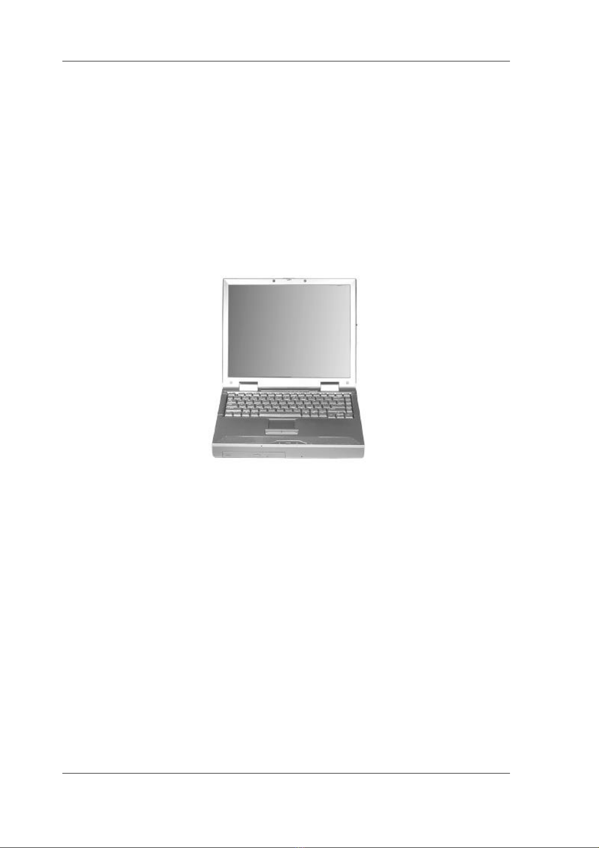
Getting to Know the NEC Versa ....................................................................................................1-2
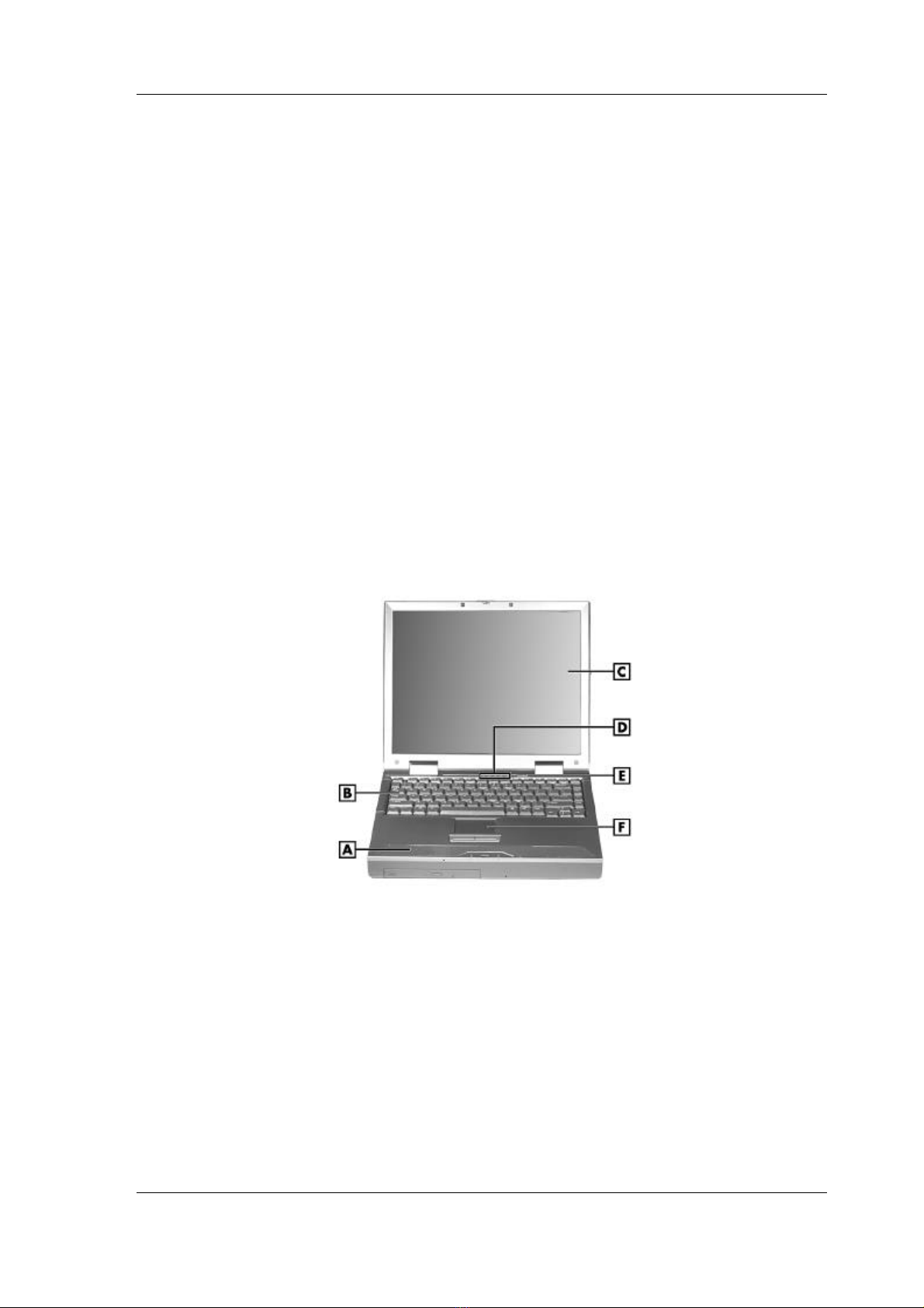
Around the Front of the System......................................................................................................1-3
LCD Panel ...............................................................................................................................1-3
Base Unit .................................................................................................................................1-3
Operating Status LEDs.............................................................................................................1-4
Power Button ................................................................................................................1-4
Keyboard .................................................................................................................................1-5
Front Features ..........................................................................................................................1-7
Around the Back of the System......................................................................................................1-8
Around the Left Side of the System................................................................................................1-9
Around the Right Side of the System............................................................................................1-10
Around the Bottom of the System.................................................................................................1-11
Internal Components....................................................................................................................1-12
Hard Disk Drive.....................................................................................................................1-12
File Bay..................................................................................................................................1-12
VersaBay III...........................................................................................................................1-12
CPU Board.............................................................................................................................1-12
Audio Board...........................................................................................................................1-12
Main Battery ..........................................................................................................................1-12
CMOS Battery........................................................................................................................1-12
Bridge Battery........................................................................................................................1-12
ChipSet........................................................................................................................................1-13
2 System Configuration and Setup
Power Sources for Your NEC Versa...............................................................................................2-2
Using the AC Adapter ..............................................................................................................2-2
Connecting the AC Adapter......................................................................................................2-2
Powering the System On and Off..............................................................................................2-3
Using the Battery......................................................................................................................2-3
Determining Battery Status.......................................................................................................2-4
Battery Gauge LEDs.................................................................................................................2-5
Low Battery Status...................................................................................................................2-5
Returning the Battery to its normal state....................................................................................2-5
Extending Battery Life..............................................................................................................2-5
Battery Handling......................................................................................................................2-6
Replacing the Battery ...............................................................................................................2-6
Battery Precautions...................................................................................................................2-9
Precautions for Recharging the Battery .....................................................................................2-9
System Batteries.......................................................................................................................2-9
Main Battery ...............................................................................................................2-10
CMOS Battery.............................................................................................................2-10
Bridge Battery.............................................................................................................2-10
Optional Battery..........................................................................................................2-10
BIOS Setup..................................................................................................................................2-10
BIOS Setup Main Menu .........................................................................................................2-11
Looking at Screens.................................................................................................................2-11
Using Keys.............................................................................................................................2-12
Checking/Setting System Parameters......................................................................................2-12
Resetting System Parameters..................................................................................................2-13
Standard CMOS Setup............................................................................................................2-13

iv Contents
Advanced CMOS Setup .........................................................................................................2-14
System Security Setup............................................................................................................2-15
Establishing System Passwords ..............................................................................................2-15
Hard Disk Drive Passwords....................................................................................................2-16
Establishing Hard Disk Drive Passwords .....................................................................2-16
Changing Hard Disk Drive Passwords .........................................................................2-16
Using Hard Disk Drive Password Protection................................................................2-17
Moving the Hard Disk Drive........................................................................................2-17
Power Management Setup......................................................................................................2-17
Boot Device Setup..................................................................................................................2-20
Peripheral Setup.....................................................................................................................2-21
Other BIOS Setup Options .....................................................................................................2-21
Updating the BIOS ......................................................................................................................2-22
Obtaining the BIOS Update....................................................................................................2-22
Preparing the BIOS Update Diskette.......................................................................................2-22
Enabling the BIOS Flash Switch.............................................................................................2-23
Performing the BIOS Update..................................................................................................2-25
3 Disassembly and Reassembly
Required Tools and Equipment......................................................................................................3-2
Disassembly ..................................................................................................................................3-2
Battery.....................................................................................................................................3-2
VersaBay III Device.................................................................................................................3-4
Memory Modules.....................................................................................................................3-5
Hard Disk Drive.......................................................................................................................3-6
File Bay Device........................................................................................................................3-8
Keyboard and Switch Settings..................................................................................................3-9
Switch Settings............................................................................................................3-10
Front Cover............................................................................................................................3-10
Speaker Assembly..................................................................................................................3-12
VersaGlide Assembly.............................................................................................................3-12
LED Status Board ..................................................................................................................3-13
PC Card Assembly .................................................................................................................3-13
Mini-PCI LAN/Modem..........................................................................................................3-14
CMOS Battery .......................................................................................................................3-14
Buzzer ...................................................................................................................................3-15
Top Cover and LCD Panel .....................................................................................................3-16
Audio Board ..........................................................................................................................3-18
Main Board............................................................................................................................3-18
Bridge Battery........................................................................................................................3-19
Fan Assembly ........................................................................................................................3-20
CPU Board Assembly.............................................................................................................3-20
Connector Board....................................................................................................................3-21
Reassembly .................................................................................................................................3-22

Contents v
4 System Board Layout
LED Status Board..........................................................................................................................4-2
Audio Board..................................................................................................................................4-2
Connector Board............................................................................................................................4-2
Main Board....................................................................................................................................4-2
5 Preventive Maintenance
Cleaning the Notebook Exterior .....................................................................................................6-2
Cleaning the Notebook Interior ......................................................................................................6-2
Protecting the Disk Drive...............................................................................................................6-2
Handling the Battery Pack..............................................................................................................6-3
Maintaining the LCD Quality.........................................................................................................6-3
6 Troubleshooting
Quick Troubleshooting ..................................................................................................................6-2
Helpful Questions..........................................................................................................................6-4
7 Specifications
System Components ......................................................................................................................7-2
Connector Locations......................................................................................................................7-8
Memory Map.................................................................................................................................7-9
Interrupt Controllers.....................................................................................................................7-10
Glossary
Index

1
System Overview
nGetting to Know the NEC Versa LXi
nAround the Front of the System
nAround the Back of the System
nAround the Left Side of the System
nAround the Right Side of the System
nAround the Bottom of the System
nInternal Components
nChipset

1-2 System Overview
Getting to Know the NEC Versa LXi
The NEC Versa LXi notebook computer offers you a portable system filled with exciting
resources for home, business or travel. Standard features include a powerful Intel Pentium III
450-MHz or 500-MHz microprocessor with AGP (advanced graphics port) that works together
with the latest Peripheral Component Interconnect (PCI) architecture. The 14.1-inch or 15.0-
inch TFT XGA LCD panel provides high-resolution display for sharp, effective visuals.
In addition, your system provides a high-performance hard disk drive, a diskette drive or
SuperDisk™ drive, PC card support, and a 24X CD-ROM drive or a 6X DVD-ROM drive. To
optimize your connectivity options, some models ship with an internal mini-PCI modem,
internal mini-PCI LAN, or combination internal mini-PCI LAN/modem. As a multimedia
system, your NEC Versa also provides the tools needed to create and present impressive images
using video clips and sound.
NEC Versa LXi notebook computer
To get comfortable with the notebook, read the following sections and take a tour around the
system!

System Overview 1-3
Around the Front of the System
The NEC Versa is compact with features on every side. First, look at the front of the NEC
Versa. The following sections describe front features, beginning with the liquid crystal display
(LCD) panel.
LCD Panel
Your NEC Versa LXi comes with a 1024x768, 64K colour LCD panel that you can adjust for a
comfortable viewing position. To adjust the viewing angle, gently tilt the LCD panel into
position. Depending on the model, your system is equipped with a:
n14.1-inch colour Thin Film Transistor (TFT) Extended Graphics Array (XGA) panel, or
a
n15.0-inch Thin Film Transistor (TFT) Extended Graphics Array (XGA) panel.
To adjust the LCD panel brightness press the Fn-F8 and Fn-F9 functions keys. For more details
about using the system’s function keys, see the section, “Keyboard,” later in this chapter.
Base Unit
The base unit of your NEC Versa offers the following features, which are described after the
figure.
LCD panel and base unit
A– Stereo Speakers D– Operating Status LEDs
B– Keyboard E– Power Button
C– LCD Panel F– NEC VersaGlide
nStereo Speakers — Provide stereo sound for your multimedia presentations or listening
pleasure. The built-in sound system also supports 3D sound, which simulates the latest
surround-sound technology.
nKeyboard — 85 keys with the standard QWERTY-key layout. (Models purchased
outside of the U.S. and Canada ship with country-specific keyboard layouts.)
nLCD Panel — Provides a high-resolution display for sharp, effective visuals on your
NEC Versa.

1-4 System Overview
nOperating Status LEDs — Keeps you informed of your NEC Versa's current operating
status. See the following section for details about the operating status LEDs.
nPower Button — Press the Power button to power on, power off, and to resume from
Suspend (Windows 95) or Standby (Windows 98) mode.
nNEC VersaGlide — The NEC VersaGlide works like a standard computer mouse.
Simply move your fingertip over the VersaGlide to control the position of the mouse
pointer. Use the selection buttons below the VersaGlide to select menu items.
Operating Status LEDs
Operating status LEDs
A– IDE/VBIII Devices E– Num Lock
B– Diskette Drive F– Microphone
C– Caps Lock G– Power Button
D– Scroll Lock
nIDE/VBIII devices — lights when the NEC Versa writes data to or retrieves data from
the internal hard disk drive, a SuperDisk drive in the file bay, or a device in the
VersaBay III.
nDiskette Drive — lights when the NEC Versa accesses the floppy diskette drive.
nCaps Lock — lights when Caps Lock is in effect.
nScroll Lock — lights when Scroll Lock is in effect.
nNum Lock — lights when Num Lock mode is active.
nMicrophone — A strategically positioned built-in microphone allows you to record
monophonic sound directly into your notebook computer.

System Overview 1-5
Power Button
The Power button is a “smart” switch, meaning that it recognizes when the system is in Suspend
(Windows 95) or Standby (Windows 98) mode, if the BIOS parameter “System Switch” is set to
“Sleep.” If in Suspend or Standby mode, you cannot power off until you press the Power button
to resume operation.
Put the unit in Suspend or Standby mode when you need to be away from your system for a
short period of time and want to return to where you left off. Suspend mode in Windows 95 and
Standby mode in Windows 98 shuts down all devices in the system while retaining data and
system status.
nIn Windows 95, press the Power button for less than 4 seconds to put your system into
Suspend mode.
nIn Windows 98, go to Start, Shutdown, Standby to put your system into Standby mode.
nUse the Power button in the following ways:
Press the Power button to power on.
Press the Power button to resume from Suspend (Windows 95) or Standby
(Windows 98) mode and proceed with normal operation.
Hold the Power button in place for 4 or more seconds to initiate power override
(powers off the system). Only use this option if you cannot power off your system
using Start, Shutdown.
Keyboard
The NEC Versa keyboard offers the following features, which are described after the figure.
Keyboard
A– Function Keys D– Windows Keys
B– Numeric Keys E– Control Key
C– Cursor Control Keys F– Control Keys
nFunction keys — Twelve function keys, F1 through F12, are available on the NEC
Versa keyboard. These keys work together with the Fn key to activate special functions.
Several keys are pre-programmed with dual functions, some of which are printed in blue
on the key.
Function keys are application-driven. See the specific application's user guide for
information about how each function key works within the application you are using.

1-6 System Overview
The following function key combinations are pre-programmed for the NEC Versa LXi
computer.
Fn-F3 — Toggles between four video modes; LCD, CRT, both (LCD and CRT) or TV
out.
Fn-F4 — Sets standby power management mode on, in Windows 95.
In Windows 95, press any key to resume from Standby mode.
No function when Windows 98 configured for Advanced Configuration and Power
Interface (ACPI). In Windows 98, Standby is equivalent to Windows 95 Suspend
mode. To resume from Windows 98 Standby mode, press the Power button.
Fn-F6 — Sets the beeper volume to low, medium, high, or mute.
Fn-F7 — Toggles between various power management levels in Windows 95. Beeps
indicate the level chosen as follows:
1 beep Off
2 beeps Custom
3 beeps Highest Performance
4 beeps Longest Life
No function when Windows 98 configured for Advanced Configuration and Power
Interface (ACPI).
Fn-F8 — Increases the LCD panel brightness.
Fn-F9 — Decreases the LCD panel brightness.
Fn-F10 — Toggles zoom in and zoom out.
Fn-F12 — Toggles the scroll lock off and on.
Fn-ESC — Initiates a Save-to-Ram, only in Windows 95, when the BIOS System
Switch is set to “Sleep.” Saves your working environment to memory.
Fn-Power — Initiates a save-to-file on demand, only in Windows 95, when the BIOS
Suspend option is set to “STF.” Saves your working environment to a reserved area on
the hard drive.
An additional pre-programmed function key, Fn-Left Ctrl, simulates pressing the right control
key for support of IBM 327x connections.
nNumeric keypad — Pressing NumLock on the keyboard activates the numeric keypad
numbers and functions printed in blue on the keys.
The keypad lets you type numbers and mathematical operands (+, -) as you would on a
calculator. The keypad is ideal for entering long lists of numbers.
When you press NumLock again, the keys revert to their normal functions as typewriter
keys.
nCursor Control keys — Cursor control keys let you position the cursor on the screen
where you want. On the screen, the cursor is a blinking underline, block, or vertical line
depending on the application. The cursor indicates where the next text typed is inserted.

System Overview 1-7
nWindows keys — If you have Windows 98 or 95, you can use the following two keys to
facilitate your work.
Quick access to shortcut menus
Displays the Start menu
nControl keys — Ctrl, Alt, Fn, and Shift are controls used in conjunction with other keys
to change their functions. To use control keys, press and hold the control key while
pressing another key. For example, “press Ctrl c” means to hold down the Ctrl key and
type the letter c. How the key combination works depends on the application you are
running.
nTypewriter keys — The typewriter keys (also called alphanumeric keys) are used to
enter text and characters. Keys with blue printing on them behave differently when
combined with control keys or the Fn key.
Front Features
The front features of your NEC Versa are described after the following the figure.
Front features
A– NEC VersaBay III C– Battery Charging LED
B– Power Status LED D– LCD Lid Latch
nNEC VersaBay III™ — A 24X CD-ROM drive, a SuperDisk drive, or a 6X DVD-ROM
drive comes installed in the NEC VersaBay III on the front of your system.
The VersaBay III lets you add options, including an optional second Li-Ion battery, or
an additional hard disk drive.
nPower Status LED — lights green when the system is under AC power. When the
system is under battery power, this LED lights to indicate the following:
Lights green when the system power is on.
Blinks green when the system is in Suspend (Windows 95) or Standby (Windows
98) mode.
Lights yellow (blinks when in Windows 95 Suspend mode or Windows 98 Standby
mode) to indicate that battery power is at 8% capacity or less.
Lights amber (blinks when in Windows 95 Suspend mode or Windows 98 Standby
mode) to indicate that battery power is at 3% capacity or less.
Note When both the primary and a secondary battery are installed, the power status LED
indicates the total (primary plus secondary) battery status.

1-8 System Overview
nBattery Charging LED — lights to indicate battery charging activity.
Lights amber when the primary battery is charging. Blinks amber to indicate an
error. The primary battery is installed in the battery bay.
Lights green when the secondary battery is charging. Blinks green to indicate an
error. The secondary (optional) battery is installed in the VersaBay III.
nLCD Lid Latch — Secures the LCD panel when closed.
Around the Back of the System
You’ll find system ports for connecting optional devices (like a printer, a docking station, or an
external monitor) on the back of your NEC Versa. These ports are described after the figure.
Back features
A– PortBar Notches E– External Monitor Port
B– PS/2 Port F– Expansion Port
C– Serial Port G– AC Power Port
D– Parallel Port
nPortBar Notches — Secure the PortBar to the back of the system.
nPS/2 Port — Connects an external PS/2-style mouse or a PS/2-style keyboard to the
system. With an optional Y-cable adapter, you can connect both a mouse and a keyboard
at the same time.
nSerial Port — Connects an external modem or other serial device.
nParallel Port — Connects a parallel printer or other parallel device. The port is an
Enhanced Capabilities Port (ECP). The ECP standard provides you with a greater
processing speed than the conventional parallel port. It also supports Enhanced Parallel
Port (EPP), bi-directional and uni-directional protocols.
nExternal Monitor (Video) Port — Attaches an external monitor to your NEC Versa. You
can run the LCD display and the external monitor simultaneously or run either alone.
nExpansion Port — This port (also called the Docking port) provides a connection for
NEC Versa LXi options including the NEC Versa Dock and the NEC Versa PortBar.
Only dock the NEC Versa LXi system on the NEC Versa Dock. The
cover of the NEC Versa Dock is specially designed to allow for proper system cooling.
nAC Power Port — Use the power jack to attach the NEC Versa to a DC power source,
such as the AC adapter or the optional DC auto adapter.

System Overview 1-9
Around the Left Side of the System
The left side of your NEC Versa offers the following features, which are described after the
figure.
Left side features
A– TV Out (S-video) E– LAN Port (optional)
B– TV Out (RCA) F– USB Ports
C– Fan G– PC Card Slots
D– Modem Port (optional)
nTV Out (S-video)Port — Lets you use a television set equipped with an S-video input
jack as an external monitor. This port supports both NTSC and PAL signals.
nTV Out (RCA) Port — Lets you use a television set equipped with a standard RCA jack
as an external monitor. This port supports both NTSC and PAL signals.
Note The TV Out ports do not support the SECAM signal used in some countries.
nFan — Allows your system to cool properly and maintain a safe operating temperature.
Always keep the fan vents unobstructed to allow proper system cooling.
nModem Port — Uses an RJ-11 cable to connect your internal modem to an analogue
telephone line. (Available if optional mini-PCI modem or mini-PCI LAN/modem
combo installed.)
nLAN Port — Uses an RJ-45 cable to connect your system to a local area network.
(Available if optional mini-PCI LAN or mini-PCI LAN/modem combo installed.)
nUSB Ports — Each Universal Serial Bus (USB) port allows you to connect up to 127
USB-equipped peripheral devices (printers, monitors, scanners, etc.) to your NEC
Versa.
nPC Card slots — Provide two slots for inserting two Type II PC cards or one Type III
PC card.

1-10 System Overview
Around the Right Side of the System
The right side of the NEC Versa offers the following features, which are described after the
figure.
Right side features
A– Volume Control E– IR port
B– Headphones/External Speakers F– Kensington Lock
C– Line-In G– File Bay
D– External Microphone H– Battery Bay
nVolume Control — Allows you to control the speaker and headphone volume.
nAudio ports
Headphones — Connects external headphones or speakers to your NEC Versa.
Plugging in headphones disables the built-in system speakers.
Line-In — Uses another audio system, like a home stereo, as an input source. Use a
cable to connect to the Line-Out port on the other audio system to record or play in
stereo.
External Microphone (MIC) — Connects an external microphone for monophonic
recording or amplification through the unit. Plugging in an external microphone
disables the built-in microphone.
nIR Port — Use this infrared (IR) port to transfer files between your NEC Versa and an
IR-equipped desktop or notebook computer or to print to an IR-capable printer.
Note Your NEC Versa LXi ships with the IR port disabled. ”
nKensington Lock — Provides added security by installing an optional Kensington Lock.
nFile Bay — Your NEC Versa ships with a 3.5-inch, 1.44-MB diskette drive or the
SuperDisk drive installed in the file bay.
nBattery Bay — Contains the system’s main, twelve-cell, Lithium-Ion (Li-Ion) battery.

System Overview 1-11
Around the Bottom of the System
The bottom of the NEC Versa offers the following features, which are described after the figure.
Bottom features
A– Height Adjustment Feet E– NEC VersaBay III
B– Memory Module Bay F– NEC VersaBay III Release Latch
C– Battery Bay Release Latch G– Main Battery Bay
D– NEC VersaBay III Release Lock H– Vents
nHeight Adjustment Feet — Modifies the angle of the NEC Versa for easier viewing and
typing.
nMemory Module Bay — Stores the system’s memory modules.
nBattery Bay Release Latch — Releases and removes the system’s main battery.
nNEC VersaBay III™ Release Lock — Unlocks the VersaBay III for device removal.
nNEC VersaBay III — A 24X CD-ROM drive, a SuperDisk drive, or a 6X DVD-ROM
drive comes installed in the NEC VersaBay III on the front of your system.
The NEC VersaBay III lets you add options, including an optional second Li-Ion
battery, or an additional hard disk drive.
nNEC VersaBay III Release Latch — Releases a device from the NEC VersaBay III.
nBattery Bay — Contains the system’s main, twelve-cell, Lithium-Ion (Li-Ion) battery.
nVents — Allows your system to cool properly and maintain a safe operating
environment.

1-12 System Overview
Internal Components
Review the following sections for a description of the system’s internal hardware.
Hard Disk Drive
A standard 2.5-inch, 9.5 mm or 12.7 mm hard disk drive ships with the system.
File Bay
The NEC Versa LXi ships with a 3.5-inch, 1.44 MB diskette drive or the SuperDisk drive
installed in the file bay.
VersaBay III
A 24X CD-ROM drive or a DVD-ROM drive comes installed in the NEC VersaBay III on the
front of the system.
CPU Board
The CPU board is a rectangular-shaped board located above the main board. The CPU board is
part of a subassembly, which includes a heat sink and the CPU board.
Audio Board
The audio board provides the NEC Versa system with its audio I/O capabilities via a line-in
jack, headphone and microphone jacks. It is situated on top of the main board.
Main Battery
The twelve-cell Lithium-Ion (Li-Ion) battery provides the main power source in your NEC
Versa LXi computer. See Chapter 9 for a list of battery specifications. In addition to this battery,
the CMOS battery and bridge battery also provide system power.
CMOS Battery
This lithium battery provides battery backup and prevents data loss in the system's
complementary metal oxide semiconductor (CMOS) RAM. This memory area contains
information on the system's configuration, for example, date, time, drives, and memory. The
CMOS battery charges when your NEC Versa is connected to AC power. The CMOS battery
may discharge completely if the NEC Versa notebook remains unused for an extended period of
time.
Bridge Battery
The bridge battery saves your system status in Suspend (Windows 95) or Standby (Windows 98)
mode, giving you time to install a fully charged battery or plug in AC power when your battery
charge becomes low.
Connect your NEC Versa system to AC power for a full 24 hours before
using it on battery power for the first time. Doing so insures that the bridge battery is fully charged
and that no data is lost during a battery change.

System Overview 1-13
ChipSet
The following table provides information on the system chipset.
System Chipset
Chip Manufacturer Description
Intel Pentium III 450-MHz, 500-MHz;
with AGP Intel 450 or 500 MHz CPU
Mobil Triton II and 82371MB PIIX4M Intel System Controller
PC97338VJG National Semiconductor Super I/O
Savage/MX S3 Video
ES1921 ESS Audio
M38813E4 Mitsubishi Keyboard Controller
TIPC11450 Texas Instruments PCI CardBus Controller
Table of contents
Other NEC Laptop manuals

NEC
NEC Packard Bell EasyNote M5 Installation instructions

NEC
NEC VersaPro VG17H/BB-D User manual

NEC
NEC VERSA TXI User manual

NEC
NEC VERSA SXI Guide

NEC
NEC Versa 2500 Series User manual

NEC
NEC VERSA FX User manual

NEC
NEC VERSA S User manual

NEC
NEC VERSA 5000 Series User manual

NEC
NEC ShieldPRO FC-N21S User manual

NEC
NEC VERSA LX AGP VIDEO - Operating manual

NEC
NEC ShieldPRO FC-N21S User manual

NEC
NEC US40a User manual

NEC
NEC VERSA N1100 Series User manual

NEC
NEC Versa E6000 Installation instructions

NEC
NEC VERSA FXI User manual

NEC
NEC VXI Series User manual

NEC
NEC 2600 User manual

NEC
NEC 2600 User manual

NEC
NEC VERSA V User manual

NEC
NEC Versa S900 Installation instructions