NEFF CV 7760 N User manual

CV 7760 N
C77V60N01
9000392549
Neff GmbH
Carl-Wery-Str. 34/81739 München
1
ac
b
c
d
20 mm
520 mm
min.
45 mm
min.
45 mm
min.
45 mm
454 mm
950 mm
450+2 mm
594 mm
550 mm
550 mm 950 mm
450+2 mm
560+8 mm
560+8 mm
560+8 mm
590+2 mm
550 mm
2
3

4
1.
x
y
4.
3.
d
2.
b
en
Anschluss
Das Gerät ist steckerfertig und darf nur an eine vorschriftsmäßig
installierte Schutzkontakt-Steckdose angeschlossen werden.
Das Verlegen einer Steckdose oder der Austausch der
Anschlussleitung darf nur vom Elektrofachmann unter Berück-
sichtigung der einschlägigen Vorschriften ausgeführt werden.
Wenn der Stecker nach dem Einbau nicht mehr erreichbar ist,
muss installationsseitig eine allpolige Trennvorrichtung mit
einem Kontaktabstand von mind. 3 mm vorhanden sein.
Nur ein fachgerechter Einbau nach dieser Montageanleitung
garantiert einen sicheren Gebrauch.
Nicht befestigte Möbel mit einem handelsüblichen Winkel an der
Wand befestigen.
Lieferumfang
Bild 1
aChassis (mit Teleskopauszügen)
bTrägerplatte mit Gerät und Front
cHolzschrauben (4 Stück)
dselbstschneidende Schrauben (2 Stück)
Einbau des Gerätes
Bild 2
Für ausreichende Durchlüftung sorgen. Dazu die Möbelrück-
wand entfernen oder eine Öffnung von 500 x 400 mm
ausschneiden.
Zwischen Wand und Schrankboden bzw. Rückwand des
darüberliegenden Schrankes muss ein Abstand von mind. 45
mm eingehalten werden. Die Lüftungsschlitze und
Ansaugöffnungen dürfen nicht verdeckt werden.
Hierzu auch die Montageanleitung des darüber oder darunter
liegenden Gerätes beachten.
Bei Einbau über einer Wärmeschublade ist eine Nischenhöhe
von 590 mm erforderlich.
Wird das Gerät direkt unter eine Dekorplatte eingebaut, ist
darauf zu achten, dass ein Lüftungsschlitz von mind. 200 cm²
vorhanden ist.
Die ideale Einbauhöhe für den Espresso-Vollautomaten,
gemessen vom Fußboden bis Unterkante Gerät, beträgt 95 cm.
Zuerst alle Teile nach Anleitung auspacken und auf
Transportschäden überprüfen.
Beschädigte Geräte dürfen nicht in Betrieb genommen
werden.
Dann das Chassis amittig und vorne bündig mit den
beiliegenden 4 Schrauben cbefestigen. Klebestreifen
entfernen, um die Auszugsfeder zu aktivieren (Bild 3).
Die Anschlussleitung in die Steckdose einstecken.
Sie darf nicht eingeklemmt werden.
Bild 4
Wichtig: Das Gerät nur auf die komplett herausgezogenen
Teleskopauszüge aufsetzen damit nach dem Einschieben die
Ausfuhrautomatik aktiviert wird.
Beide Teleskopauszüge ganz herausziehen.
Die Trägerplatte bmit dem Gerät auf die beiden
Teleskopauszüge aufsetzen. Mit den beiden Schrauben d
Das Spiralkabel des Gerätes am Chassis einstecken, nicht
überdehnen.
Steht das Gerät vor oder rastet nach dem Einschieben nicht
ein, kann es justiert werden.
Das Gerät steht vor:
Inbus SW3 einsetzen und nach links Xdrehen.
Das Gerät rastet nicht ein:
Inbus SW3 einsetzen und nach rechts Ydrehen.
Anschließend die einwandfreie Funktion der elektrischen
und manuellen Auszugsmechanik überprüfen.
1.
2.
3.
4.
Connection
connected to a correctly installed earthed socket. Only an
compliance with the relevant regulations.
If the plug is no longer accessible following installation of the
appliance, there must be an all-pole disconnector with a contact
gap of at least 3 mm on the installation side.
Only an appliance which has been correctly installed according
to these installation instructions can be used safely.
Attach loose furniture to the wall with a conventional bracket.
Included in delivery
Fig. 1
aChassis (with telescopic slides)
bSupport plate with appliance and front panel
cWood screws (4x)
dSelf-tapping screws (2x)
Installing the appliance
Fig. 2
Make sure there is adequate aeration. To do this, remove the
rear panel or cut out an opening of 500 x 400 mm.
There must be a gap of at least 45 mm between the wall and
base of the unit or the rear panel of the unit situated above.
The ventilation slots and intake openings must not be covered.
Also follow the installation instructions for the appliance situated
above or below.
If installing the appliance above a warming drawer, the height of
the recess must be 590 mm.
If the appliance is installed directly under a décor panel, ensure
that there is a ventilation slot of at least 200 cm².
The ideal installation height for the fully automatic espresso
appliance, is 95 cm.
First unpack all parts according to the instructions and check
for damage in transit.
Do not switch on a damaged appliance.
Then attach the chassis a
the enclosed 4 screws c. Remove the adhesive strip to
activate the mainspring (Fig. 3).
Plug the power cord into the socket.
Do not trap or kink the power cord.
Fig. 4
Important: The appliance must be placed on the telescopic
slides only when they are fully extended, so that the deployment
mechanism is activated when it is pushed in.
Pull out the two telescopic slides fully.
Place the support plate bwith the appliance on the two
telescopic slides. Secure with the two screws d.
Plug the helix cable of the appliance into the chassis, being
careful not to overstretch it.
If the appliance protrudes or does not engage after being
pushed in, this can be adjusted.
If the appliance protrudes:
Insert Allen key SW3 and turn it to the left X.
If the appliance does not engage:
Insert Allen key SW3 and turn it to the right Y.
Finally, check that the electrical and manual deployment
mechanism works correctly.
1.
2.
3.
4.
de ar
3
.
.
. 3
.
.
1
( ) a
b
(4x) c
(2x) d
2
.
45
.
.
.
. 590
. 200
95
.
•
.
.
a •
.c
.(3)
. •
.
4
:
.
.1
. b .2
.d
. .3
. .4
: •
X
SW3
: •
Y
SW3
•
211

fr it
3
Raccordement
sur une prise électrique avec terre, installée de manière confor-
me. La pose de la prise électrique ainsi que le remplacement du
cordon d‘alimentation de la machine doivent être effectués par
dans l‘installation un système coupe-circuit avec une distance
entre contacts d‘au moins 3 mm.
cornière de type courant.
Contenu de la livraison
Fig. 1
a
bPlaque support avec machine et plaque frontale
c
d
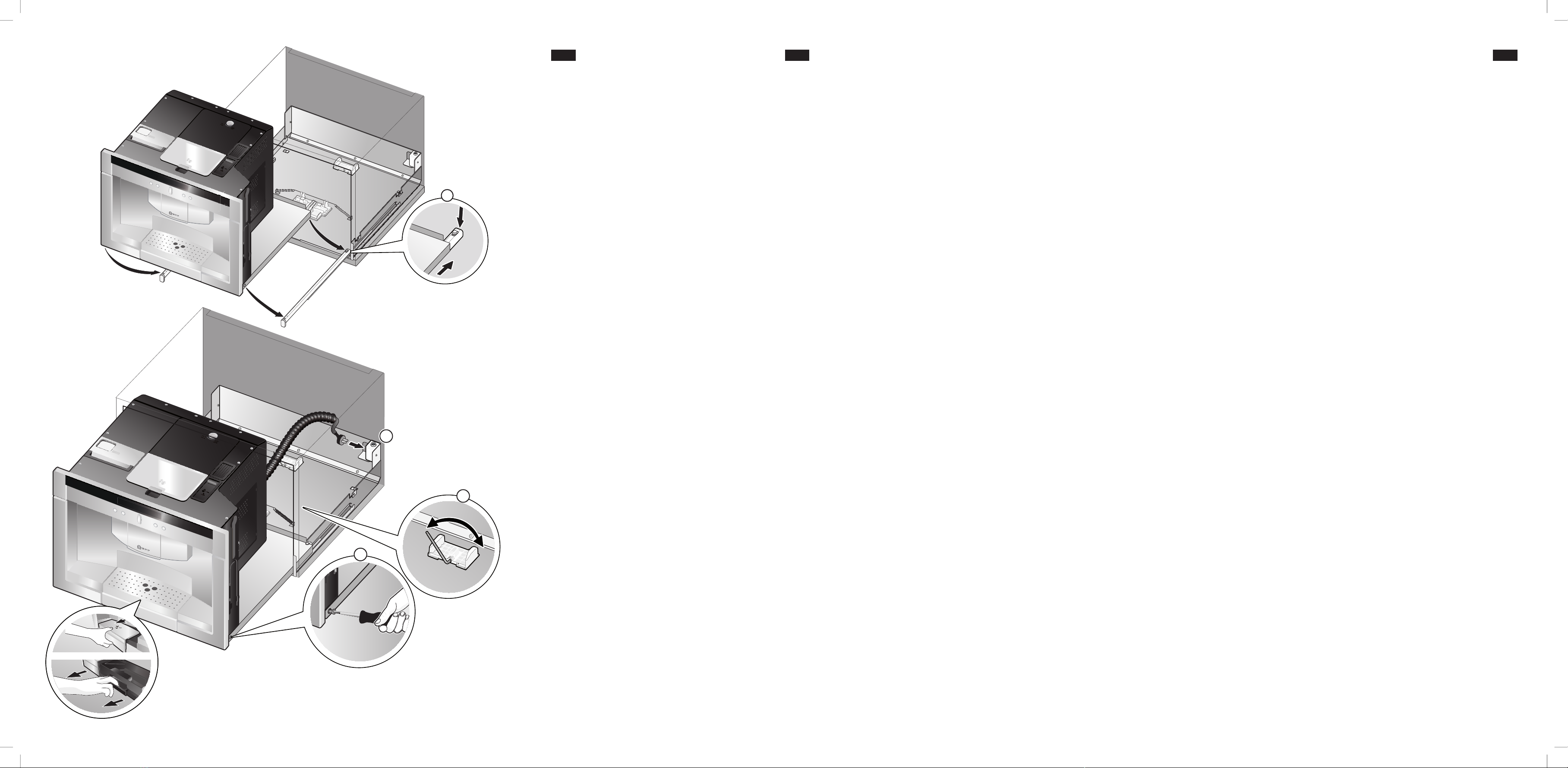
Montage de la machine
Fig. 2
d‘aspiration.
l‘appareil situé en dessous ou au dessus.
disposer d‘une hauteur de niche de 590 mm.
Si la machine est montée directement derrière un panneau
décoratif, il faut veiller à avoir une fente de ventilation d‘au
moins 200 cm².
le transport. Ne pas mettre en service une machine
cle châssis aen le centrant et
Fig. 3
Le cordon d‘alimentation ne doit pas être coincé.
Fig. 4
Important:
de placer la machine de manière à activer le dispositif
Tirer entièrement
Placer la plaque support b
d.
Brancher le cordon spiralé de la machine sur le châssis, ne
pas trop l‘étirer.
Si la machine est placée trop en avant ou si elle ne
La machine est trop en avant :
X.
La machine ne s‘enclenche pas :
Utiliser une clé allen de 3 et tourner vers la droite Y.
Ensuite, contrôler le bon fonctionnement du mécanisme
électrique et manuel d‘extraction.
1.
2.
3.
4.
Connessione
L’apparecchio è pronto per essere connesso e può essere
possono essere installate solo da un elettricista specializzato, in
essere presente nell’impianto un separatore onnipolare con
distanza di contatto di almeno 3 mm.
-
Materiali forniti
Figura 1
a
bPiastra di supporto con apparecchio e frontalino
c
d
Montaggio dell’apparecchio
Figura 2
Tra la parete e il fondo dell’armadio o la parete posteriore
Non coprire le fessure di ventilazione e i fori di aspirazione.
A tale scopo attenersi anche alle istruzioni di installazione
dell’apparecchio soprastante o sottostante.
necessaria un’altezza della nicchia di 590 mm.
decorativo, assicurarsi che la fessura di ventilazione sia di
aal centro e sul lato anteriore
c
adesivo per attivare le molle ( 3
La linea non deve venir incastrata.
Figura 4
Importante:-
piche completamente estratte, in modo che dopo l’inserimento
Estrarre completamente
bcon l’apparecchio su
con le due viti d.
Inserire il cavo a spirale dell’apparecchio sul chassis. Non
torcere.
X.
Se l’apparecchio non si incastra:
Y.
perfettamente sia elettricamente che manualmente.
1.
2.
3.
4.

de en
4
nl tr
4
Aansluiting
muur.
Leveromvang
Afbeelding 1
a
b
c
d
Montage van het apparaat
Afbeelding 2
-
minstens 200 cm² voorhanden is.
95 cm.
a
c.
om de veren te activeren (afbeelding 3
Afbeelding 4
Belangrijk:
volledig uit.
bmet het apparaat op de telescopische
d.
Xdraaien.
Ydraaien.
Controleer nu of de elektrische en handmatige
uitschuiffuncties correct functioneren.
1.
2.
3.
4.
duvara tespit edilmelidir.
1
a
b
c
d
2
a
c
3
4
Önemli:
tam olarak
b
d
X
Cihaz yerine oturmuyor:
Y
1.
2.
3.
4.

fr it
5
da no
5
Tilslutning
Leveringsomfang
Fig. 1
a
b
c
d
Installation af apparat
Fig. 2
enhed.
590 mm.
a
c
3
Fig. 4
Vigtigt:
helt ud.
b
d.
X.
Y.
Kontroller fejlfri funktion for hhv. elektrisk og manuel
udtræksmekanisme.
1.
2.
3.
4.
Tilkopling
Leveringsomfang
Fig. 1
a
b
c
d
Montering av apparatet
Fig. 2
ovenfor eller nedenunder.
590 mm.
95 cm.
a
c
Fig. 3
Fig. 4
Viktig:
inn.
helt ut.
b
d.
X.
Y.
Kontroller derpå om den elektriske og manuelle
uttrekksmekanismen fungerer som den skal.
1.
2.
3.
4.

de en
6
sv
6
Maskinen
Leveransomfattning
Bild 1
a
b
c
d
Montera maskinen
Bild 2
mm.
mm.
95 cm.
a
c
Bild 3
Bild 4
Viktigt:
in.helt.
b
d.
X.
Y.
Kontrollera sedan att den elektriska och manuella
utdragningsmekaniken fungerar felfritt.
1.
2.
3.
4.
Liitäntä
Toimituksen sisältö
Kuva 1
Laitteen asentaminen
Kuva 2
asennusohje.
95 cm.
a
c
(kuva 3
Kuva 4
Tärkeää:
kokonaan ulos.
b
d.
X.
Y.
Tarkasta sen jälkeen sähkökäyttöisen ja käsikäyttöisen
ulosvetomekanismin moitteeton toiminta.
1.
2.
3.
4.

fr it
7
es ru
7
Conexión
en un enchufe con contactos de puesta a tierra correctamente
como mínimo 3 mm.
Volumen de suministro Figura 1
a
bPlaca de soporte con la máquina y panel frontal
c
d
Instalación de la máquina Figura 2
temperatura, será necesario mantener una distancia de 590 mm
de altura.
200 cm² como mínimo.
máquina es de 95 cm.
transporte.
aen el centro y delante a ras con
los cuatro tornillos adjuntos c
el muelle ( 3
Figura 4 Importante:
completamente
completamente
Coloque la placa de soporte bcon la máquina en los dos pies
d.
nivelarse.
X.
Y.
A continuación compruebe si el sistema de extracción
eléctrico y manual funcionan correctamente.
1.
2.
3.
4.
1
a
b
c
d
2
a
c
3
4
b
d.
X.
Y.
1.
2.
3.
4.

de en
8
pt el
8
electricistas e deve ser efectuada de acordo com os
haver um disjuntor tripolar com uma distância de pelo menos 3
mm entre os contactos.
Âmbito de fornecimento
Figura 1
a
bBase de suporte com aparelho e face
c
d
Figura 2
directamente por cima deve haver uma distância de pelo menos
tapadas.
tem de ter 590 mm de altura.
pelo menos 200 cm² .
aparelho, é de 95 cm.
a
parafusos c
( 3
Figura 4
Importante:
Estender totalmente
b
d.
X.
Y.
1.
2.
3.
4.
1
a
b
c
d
2
a
c
( 3
4
b
d.
X
Y
1.
2.
3.
4.

bg
1
a
b
c
d
2
a
c.
3
4
b
d.
X.
Y.
1.
2.
3.
4.
9

1010
pl
Zakres dostawy
Rysunek 1
a
b
c
d
Rysunek 2
a
c.
rysunek 3
Rysunek 4
b
d.
X.
Y.
1.
2.
3.
4.
hu
1ábra
a
b
c
d
2ábra
Ezután a vázat ac
3ábra
4ábra
Fontos:
teljesen.
b
d
X.
Y.
1.
2.
3.
4.
Other manuals for CV 7760 N
4
This manual suits for next models
1
Table of contents
Other NEFF Coffee Maker manuals

NEFF
NEFF CV 7760 N User manual

NEFF
NEFF C17KS61H0 User manual

NEFF
NEFF C766 Series User manual

NEFF
NEFF CT636LE Series User manual

NEFF
NEFF C7660 User manual

NEFF
NEFF C1.KS61N0 User manual

NEFF
NEFF CV 7760 N User manual

NEFF
NEFF C1.KS61G0 User manual

NEFF
NEFF C1.KS61H0 User manual

NEFF
NEFF CV 7760 N User manual