* When making the brake a short cycle of 5 sec or less, use wiring for 60W or
90W. (Using external resister for brake)
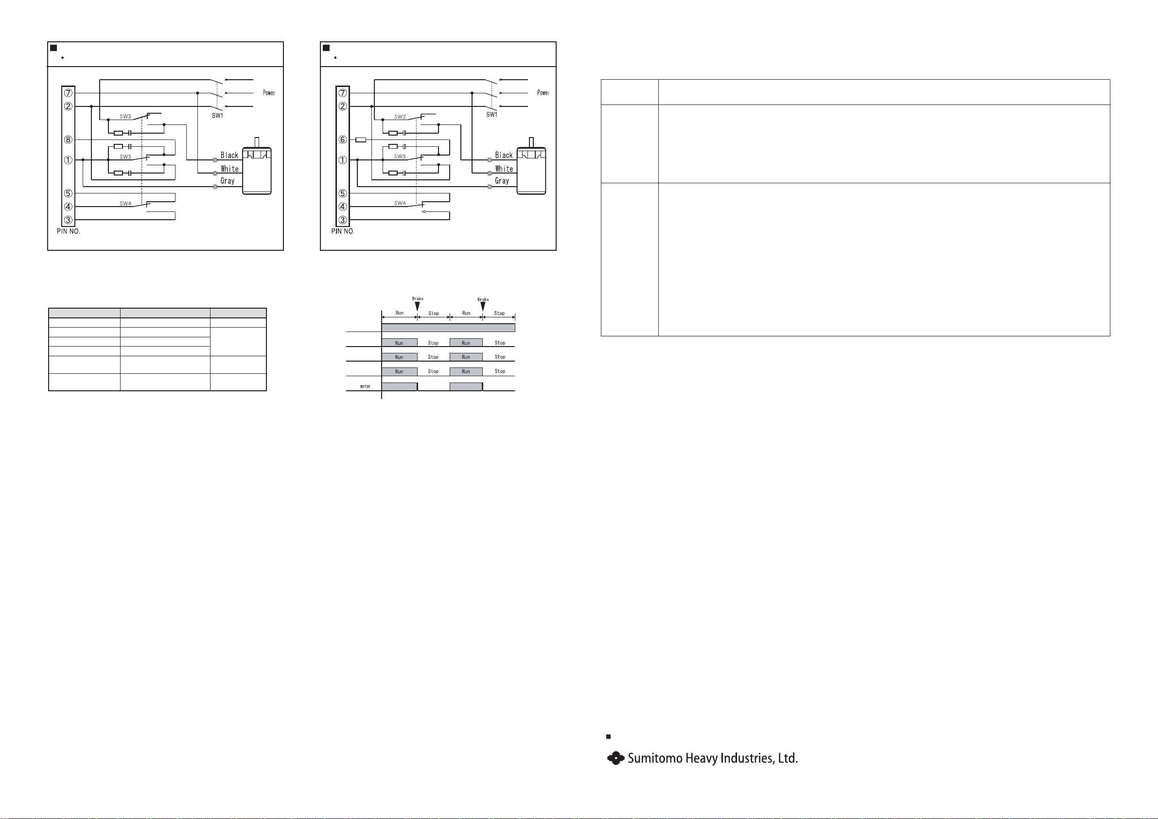
* Use external resister for brake(30Ω 20W).
Switch No. Capacity of switch Remarks
SW1 AC250V 5A or more
SW2 AC250V 7A or more It must
synchronize.
SW3 AC250V 7A or more
SW4 DC20V 10mA
R:External resister for
brake 30Ω 20W
CR circuit
Ro,Co
Ro = 5-200Ω
Co = 0.1-0.2μF for AC250V
Option
Type : EACR25
Note: CR circuit is for the surge voltage protection.
CW
SW 4
CW
SW 3
SW 2
SW 1ON
25W, 40W Induction Motor
7.Input signal and motor operation (Fig.1)
• Clockwise (CW) operation input (induction motors)
When the CW operation input is turned ON, the motor shaft rotates clockwise. When turned OFF, the motor stops instantly. Induction
motors operate using the CW operation input. When connected as shown in the diagram, the motor operates in the clockwise direction.
To operate the motor counterclockwise, switch the gray and brown motor lead wires (the white and brown wires for a 220 to 240V/50Hz
motor).
• Counterclockwise (CCW) operation input (reversible motors)
When the CCW operation input is turned ON, the motor shaft rotates counterclockwise. When turned OFF, the motor stops instantly.
If the CW and CCW operation inputs are both turned ON at the same time, CW is given priority.
• Brake release input (induction motors, reversible motors)
When the brake release input is turned ON, the electronic brake won't operate. If the CW or CCW input is turned OFF in this condition, the
motor stops naturally after losing its inertia. If the brake release input is turned OFF, the electronic brake will operate. If the CW or CCW
input is turned OFF in this condition, the motor stops instantly.
8.Wiring connection cautions
• Don't try to switch the motor's operation direction in the 0.5-second interval after an instant motor stop.
• When using a short motor operation cycle, be sure the surface temperature of the motor case doesn't exceed 90°C.
• Don't start or stop the motor by turning the AC power supply ON/OFF, as surge voltage from the switch may cause product damage.
• Turn the power OFF when the motor is not in use for extended periods.
• Use the shortest possible distance when wiring the motor and brake pack, and brake pack and external controller.
• Use wires with a across-sectional area of at least 0.75mm for the motor wiring and AC power wiring.
• Don't bundle the motor wiring/AC power wiring (terminal Nos. 1, 2, 3, 9 and 10) with the signal wiring (terminal Nos. 4, 5, 6, 7 and 8). Install
the two sets of wiring at least 10cm apart.
• Don't solder anything to the brake pack's terminal pins directly.
• Turn the power OFF before inserting the brake pack into the socket, Insert the brake pack securely.
• Always ground the terminal of pin No.6, if motor operation will include instant stops.
60W, 90W Induction Motor
Fig.3 Example of running operation
2 V
SW3
SW2
SW4
R o Co
R o Co
R o Co
1 U
3 W
R
S
T
Motor
Brake
Brake
Brake
Run
Run
Run
SW3
SW2
SW4
R o Co
R o Co
R o Co
1 U
2 V
3 W
R
S
T
R
30Ω20W
Motor
Brake
Brake
Brake
Run
Run
Run
Specifications, dimensions, and other items are subject to change without prior notice.
Power Transmission & Controls Group
Headquarter ThinkPark Tower, 1-1 Osaki 2-chome, Shinagawa-ku, Tokyo 141-6025, Japan
No.EM0206E-4.1
EE01 Printed 2023.01
9. Warranty
The scope of warranty of our delivered products is limited only to what we manufactured.
Warranty (period and description)
Warranty
period
The warranty period applies only to new products and represents 18 months after the shipment or 12 months after the ac-
tual operation, whichever is shorter.
Description
If the product failed within the warranty period, during which despite a proper mounting, connection and maintenance &
administration are followed according to the maintenance manual, and the product is properly run based on the specica-
tion on the catalog or under conditions agreed separately, we will repair or provide an alternative product at our discretion
for free of charge, except the exclusions below.
However, as far as the product is connected with customers' other devices, we will not indemnify those expenses on dis-
mounting from/mounting on the devices, etc. and other associated construction expenses, transportation expenses and
opportunity loss and operation loss the customers suered from, and other indirect damages.
Exclusion
from the
warranty
The following items will be excluded from the warranty:
1. A breakdown resulting from defects in the installation of the product and coupling with other devices, etc.
2. A breakdown resulting from insucient maintenance & administration and improper handling of the product, including
a case that the product is not stored according to our dened storage manual.
3. A breakdown resulting from operation which does not fall within our specication and other operation conditions and
use status we hardly can know.
4. A breakdown resulting from defects, special specication, etc. of device prepared and connected by customer.
5. When this product is disassembled or modied by the customer, or the parts are replaced by the customer.
6. A breakdown resulting from defects in parts supplied or specied by customers.
7. A breakdown caused by inevitable force including earthquake, re, ood disaster, salt damage, gas damage, and light-
ning strike, etc.
8. Natural wear and tear, abrasion, and deterioration of such relevant consumable parts as a bearing and oil seal, etc. under
normal usage.
9. A breakdown caused for reasons not attributable to each of the above item.


