Neitz IO-A LED User manual

Binocular Indirect Ophthalmoscope
IO-αLED (Battery-powered Type)
User’s Manual
Thank you for purchasing the NEITZ Binocular Ophthalmoscope IO-αLED (Battery-powered
Type). This is a battery-powered device to examine the inside and fundus of the eyes by
illuminating with an LED bulb. The device is powered by the Battery Pack IO-BPⅡwhich can be
attached to the Headband or a belt or the like
Please read this User’s Manual carefully before use to avoid unexpected accidents and store it in
a safe place for future reference.
TD11-12610004E-3

i
Table of Contents
1Important Information................................................................................................................2
1.1 Intended Use...................................................................................................................... 2
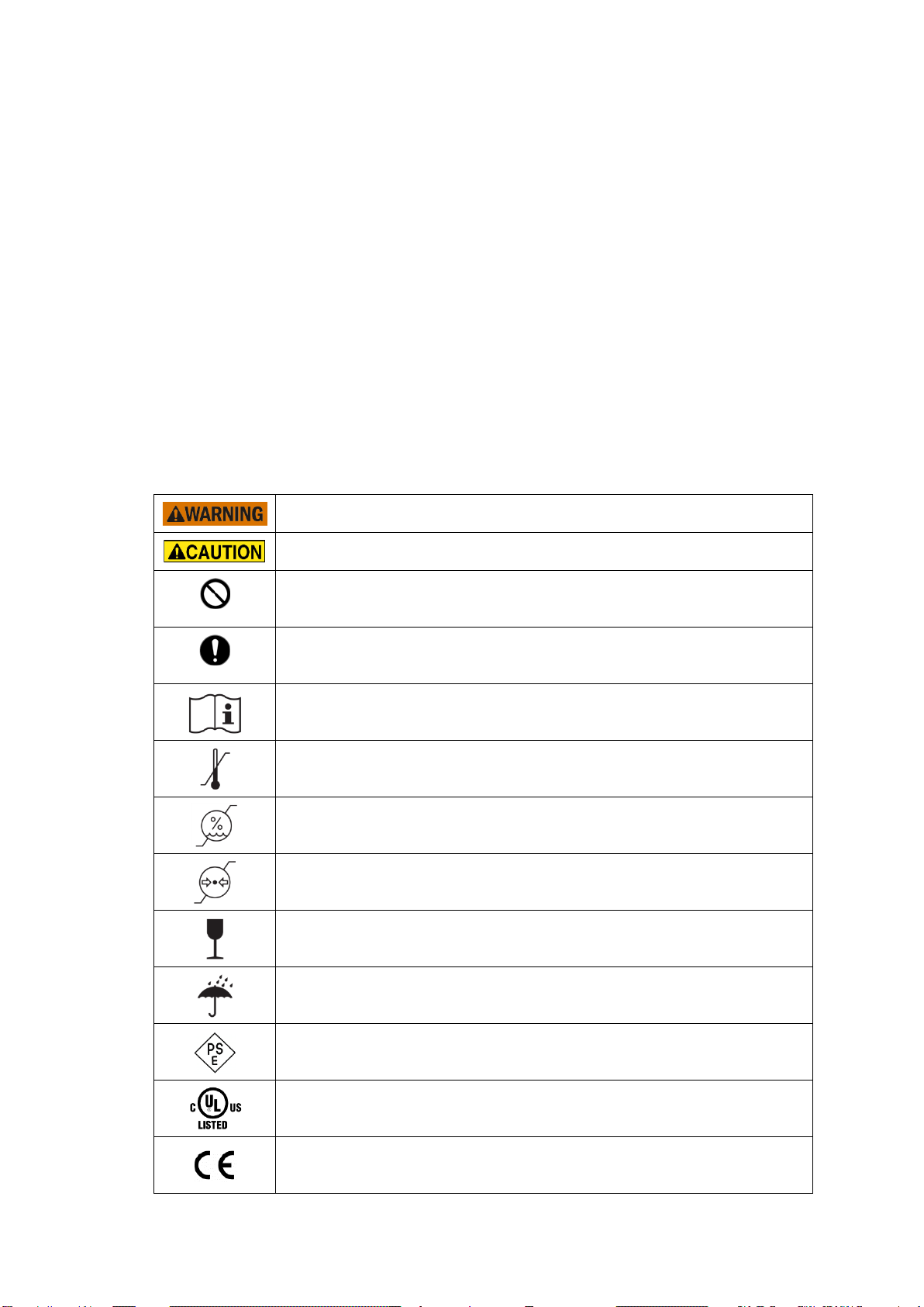
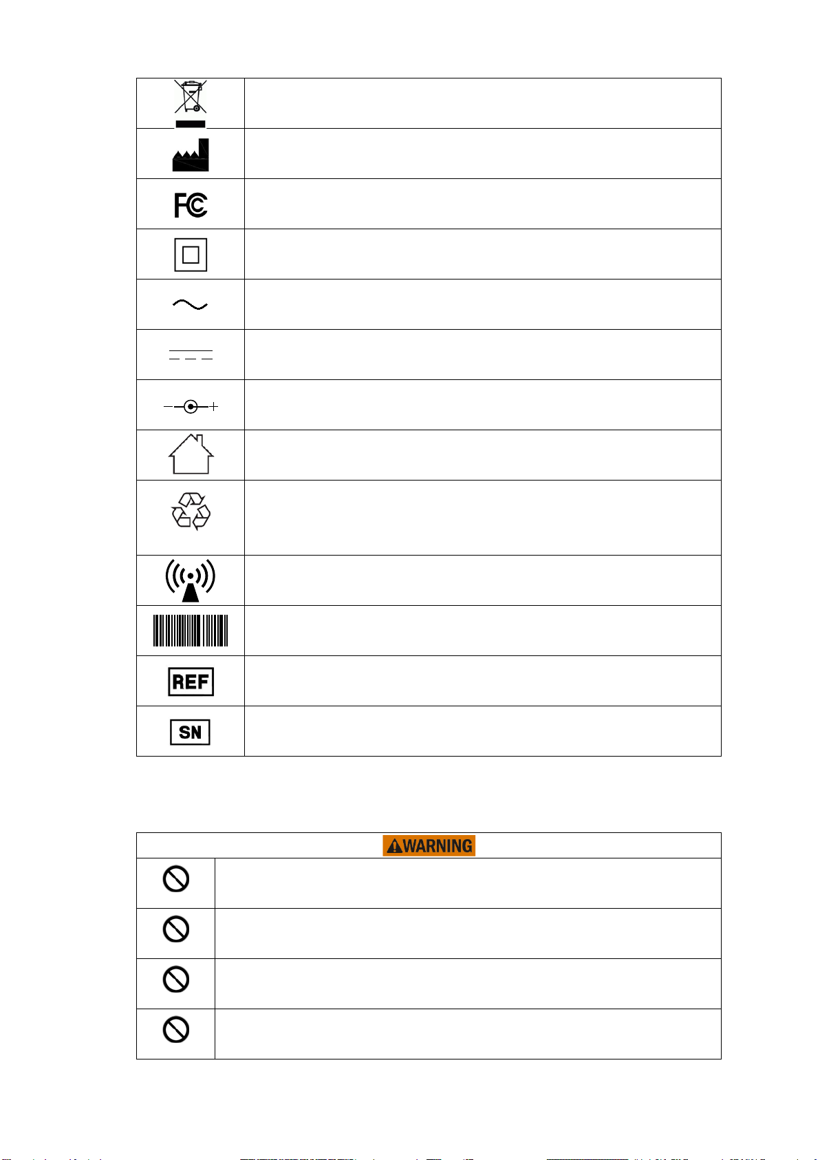
1.2 Symbols ............................................................................................................................. 2
1.3 Safety Information..............................................................................................................3
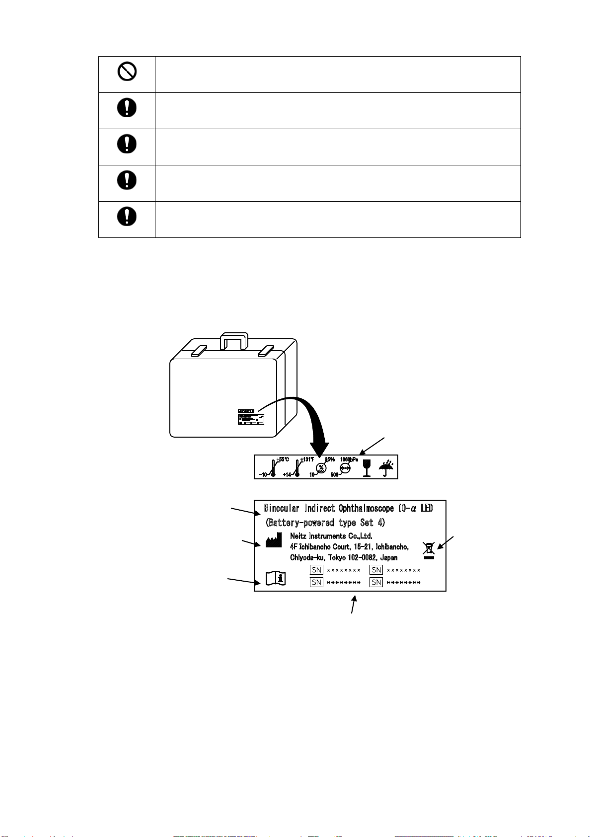
1.4 Labeling on Package.........................................................................................................5
2Checking Package Contents..................................................................................................... 6
2.1 Composition.......................................................................................................................6
2.2 Nomenclature..................................................................................................................... 7
2.2.1 IO-α Main Unit ............................................................................................................7
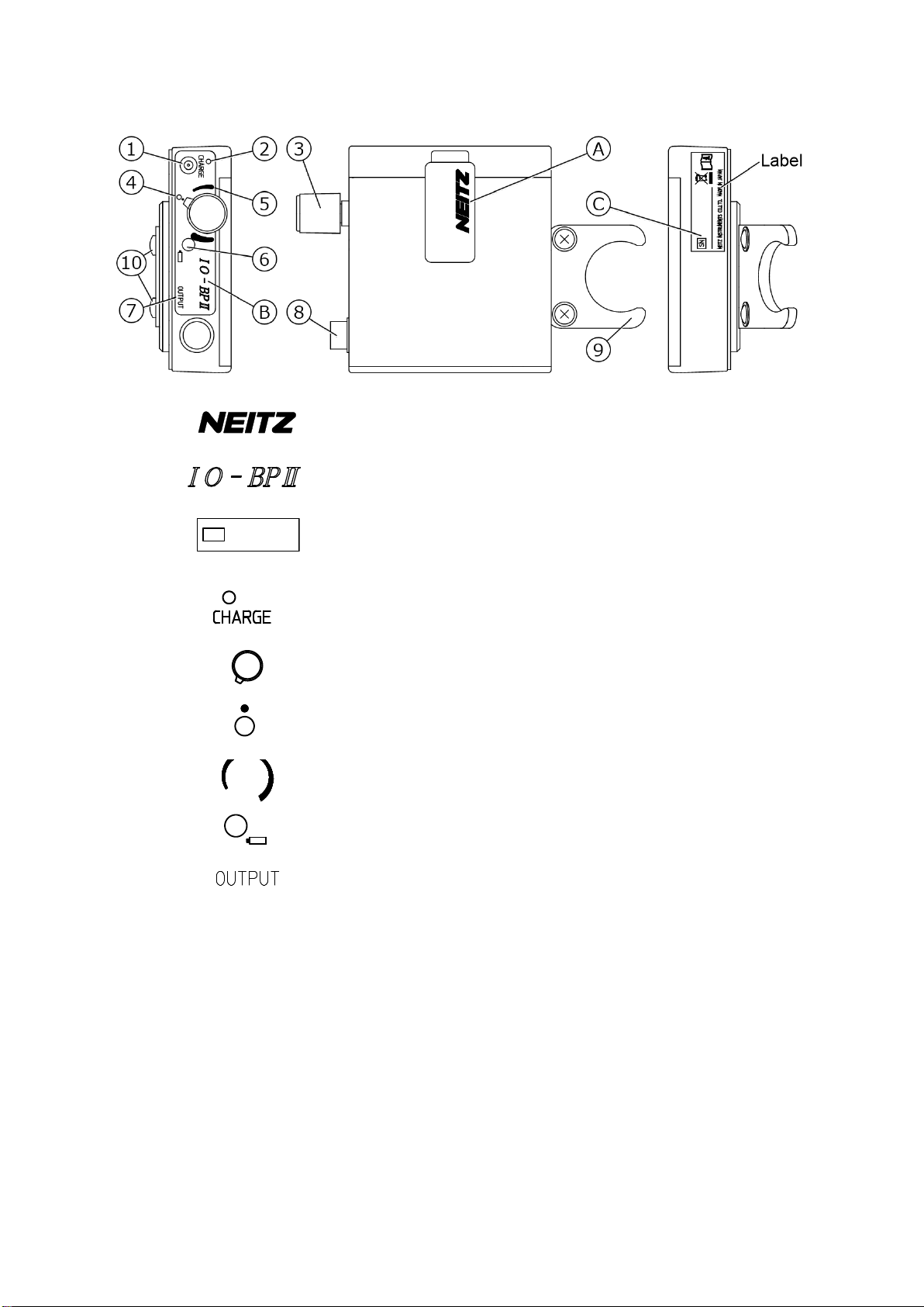
2.2.2 IO-BPⅡ...................................................................................................................... 9
3Operation.................................................................................................................................10
3.1 Preparation ......................................................................................................................10
3.1.1 Charging the IO-BPⅡ............................................................................................... 10
3.1.2 Attaching the IO-BPⅡ.............................................................................................. 10
3.1.3 Connecting the IO-BPⅡto the Scope Unit................................................................11
3.2 Operation......................................................................................................................... 12
3.2.1 Wearing the IO-α...................................................................................................... 12
3.2.2 Positioning the Scope Unit....................................................................................... 12
3.2.3 PD Adjustment..........................................................................................................12
3.2.4 Illumination................................................................................................................12
3.2.5 Examination..............................................................................................................13
3.2.6 Using the Teaching Mirror......................................................................................... 15
3.2.7 Turning Illumination Off............................................................................................. 15
4Maintenance............................................................................................................................16
4.1 Cleaning...........................................................................................................................16
4.1.1 Cleaning the Optics.................................................................................................. 16
4.1.2 Cleaning the Headpad.............................................................................................. 16
4.1.3 Cleaning Other Exterior Parts .................................................................................. 16
4.2 Replacing the LED Bulb................................................................................................... 16
4.3 Replacing the IO-BPⅡ....................................................................................................17
4.4 Disposal........................................................................................................................... 17
5Troubleshooting....................................................................................................................... 18
6Specifications..........................................................................................................................19
7Contact Information.................................................................................................................20
ANNEX A........................................................................................................................................21
ANNEX B........................................................................................................................................ 22

1 / 25
1 Important Information
For the U.S. Market;
CAUTION: Federal law restricts this device to sale by or on the order of a physician.
1.1 Intended Use
The NEITZ Binocular Indirect Ophthalmoscope IO-αLED (Battery-powered Type)
(hereinafter referred to as “IO-α”) is a battery powered medical device containing an LED
bulb for illumination and viewing optics intended to examine the media (cornea, aqueous,
lens and vitreous) and retina of the eye.
Do not use this device for any purpose other than its intended use.
1.2 Symbols
The following symbols are used on this manual and/or package to assist you in proper
handling and use of the IO-α, and to warn and caution you of potential hazards to yourself
and others.
Potentially hazardous situation which, if not avoided, could result in
death or serious injury
Potentially hazardous situation which, if not avoided may result in minor
or moderate injury or property damage
Prohibited actions (must not be performed)
Required actions (must be performed)
Consult User’s Manual for information on proper use
Temperature limits (°C) for storage and transport
Relative humidity limits (%) for storage and transport
Atmospheric pressure limits (hPa) for storage and transport
Fragile. Handle with care
Keep dry
Meets Japanese Product Safety, ElectricalAppliance and Materials Law
requirements
“UL certified” product
Product complies with the European requirements for safety, health,
environment and customer protection. (not applicable to the IO-α)
Prohibited
Instruction

2 / 25
Product must not be disposed of with general household waste under
the WEEE directive
Manufacturer’s name and address
Federal Communications Commission approved product
Class II equipment
Alternating Current,AC
Direct Current, DC
Polarity of DC plug (center pin is positive)
For indoor use only
Nickel-metal hydride rechargeable battery (must be recycled)
Potentially hazardous levels of non-ionizing radiation or RF transmitters
(not applicable to the IO-α)
Barcode for traceability purposes
Catalog number (product code)
Serial number
1.3 Safety Information
For your safety, please comply with the following precautions.
Do not use battery packs or AC adaptors other than the standard
accessories supplied by the manufacturer. Doing so may result in electric
shock or device failure.
Do not illuminate the patient’s eye for more than 1 minute per eye and be
sure to keep illumination at minimal intensity needed to view the fundus.
Do not connect the power cable to an outlet with too many other devices.
Doing so may cause injury or fire.
Do not use damaged cables or cords. Doing so may cause electric shock,
fire or device failure.
Ni-MH
Prohibited
Prohibited
Prohibited
Prohibited

3 / 25
Do not use in oxygen rich environments, in the presence of propane,
gasoline or other combustible gasses, or near dust and debris. Doing so may
cause explosion.
Do not leave the illumination of for prolonged periods or cover the device
during illumination. Doing so may cause the device to reach high
temperatures.
Never touch liquid which may have leaked from the Battery Pack. In case of
contact with the eye(s), flush with clean water without rubbing, and consult a
physician immediately. If leaked liquid gets on skin or clothing, wash with
clean water immediately. Failure to do so may result in serious injury,
including loss of eyesight.
Do not short-circuit connectors or touch them with bare hands. Doing so may
cause electric shock or device failure.
Do not attempt to disassemble or modify the device. Doing so may result in
electric shock, fire or device failure.
Never remove the cover of the battery pack. Attempting to charge
commercial batteries so may cause leakage of liquids, heat generation or
rupturing during charging.
Do not touch the device with wet hands. Doing so may result in electric
shock.
In the event of ingress of water or other liquids, unplug from the power outlet
immediately. Failure to do so may result in electric shock, fire or device
failure.
Unplug the power cable from the power outlet prior to cleaning. Failure to do
so may result in electric shock
Take care to only touch insulated parts when inserting the power plug into
the power outlet. Failure to do so may cause electric shock or fire.
Do not sterilize the device. Doing so may cause device deformation or
failure.
Do not install the device in places where it may be difficult to plug in/out
to/from the power outlet or to switch power since the plug-out from the outlet
is one of the separation methods between the device and the power supply
Do not use in excessively humid or saline environments, or places where the
device may be sprayed with water. Doing so may result in electric shock or
device failure.
Do not expose the device to direct sunlight or harmful radiation. Doing so
may lead to unexpected heating and result in device failure.
Do not attempt to charge the device in temperatures exceeding 35 °C
(95 °F). Doing so may prevent the device from charging or result in device
failure.
Do not attempt to charge the device when wet. Doing so may cause
excessive heating, fire or rupture.
Do not place heavy objects on, apply excessive tension to, or fold cables,
cords and connectors. Doing so may result in damage and electric shock or
fire.
Do not use paint thinners, cleaning agents or boiling water to clean the
device. Doing so may cause deformation or device failure.
Prohibited
Prohibited
Prohibited
Prohibited
Prohibited
Prohibited
Prohibited
Instruction
Instruction
Instruction
Prohibited
Prohibited
Prohibited
Prohibited
Prohibited
Prohibited
Prohibited
Prohibited

4 / 25
Do not immerse in cleaning detergents or rinse with water. Doing so may
cause device failure.
Unplug from the power outlet during long periods of disuse. Not doing so
may cause fire or device failure.
Allow the device to return to room temperature before unpacking. Not doing
so may cause condensation and lead to device failure.
Make sure the illumination is turned off during transport or storage and only
use the specified casing. Failure to do so may result in deformation, device
failure or fire.
When disconnecting cables, be sure to hold the plug. Never pull the cable.
1.4 Labeling on Package
The following label has been adhered to the package of the IO-αLED.
Prohibited
Instruction
Instruction
Instruction
Instruction
Environmental conditions for
transport and storage
Product Name
and Model
Manufacturer’s
Name & Address
WEEE directive
Consult User’s
Manual
Serial Number of:
S
cope Unit Headband
B
attery Pack Teaching Mirror

5 / 25
2 Checking Package Contents
2.1 Composition
Make sure to match all items in the package with the components shown below and inspect
each item for damage. Should any items be missing or damaged, do not use the IO-α and
contact your local dealer immediately. Set Type
Item
Set 4 Set 3 Set 2
IO-α Main Unit See 2.2.1 1 1 1
IO-BPⅡSee 2.2.2 1 1 1
ACAdapter
(example)
1 1 1
Extension Cord (1 m) 1 1 1
Belt Hook
1 1 1
Wiring Ring
1 1 1
Teaching Mirror
1 - -
Detachment Chart 1 - -
User’s Manual
1 1 1
Carrying Case
1 1 -
Aspheric Lens
Optional
Replacement Bulb Optional
Headpad (replacement)
Optional
IO Stand
Optional

6 / 25
2.2 Nomenclature
2.2.1 IO-α Main Unit
A
Manufacturer’s Logo
B Model Logo
C
Uses an LED bulb
D
Serial number of the Main Unit
E
Serial number of the Headband
1 Lamphouse Holds the LED bulb
2 Front Window Outputs illumination
3 Teaching Mirror Slot To insert the Teaching Mirror
4 Filter Selection Lever
Switches between “UV filter (white)”, “Red-free filter (green)”
and “Cobalt Blue Filter (blue)”
5
Filter Selection Marker
6
Aperture Selection
Lever
Switches the area of the illumination field
7
Aperture Selection Marker
8 Eyepiece A +2 D (diopters) lens is included
9 PDAdjuster
Adjusts the pupil distance (PD). The scale (54 mm to 74 mm)
is indicated above the Eyepiece
10
IlluminationAngle
Adjustment Lever
Adjusts the illumination angle. Levers located on both sides of
the Scope Unit are coupled and move in conjunction.
11
Observation Angle
Adjustment Lever
Adjusts the observation angle. Levers located on both sides of
the Scope Unit are coupled and move in conjunction.
12
Graphic display of the approximate subject pupil size.
13
Lamp Plug
Connects to the Lamp Jack of the IO-BP
Ⅱ
SN *********
SN *********
Label
A
A
B
C
D
D
E
1
2
3
4
5
6
7
8
9
10
11
12
13
14
15
16
17
18
19

7 / 25
14
Scope Unit
Fixation Knob
Loosen to position the Scope Unit
15
Headpad
Applied to the forehead to keep the Scope Unit in Place
16
Overband
Holds the Scope Unit. Can be flipped up.
17
Overband
Fixation Knob
Loosen to flip up the Overband. Tighten to keep the Overband
in place
18 Headband Cover(s)
Covers the adjustment mechanics of the Headband. For your
safety, do not remove.
19
Headband Size
Adjustment Knob(s)
Turn clockwise to tighten the Headband. Turn counter-
clockwise to loosen the Headband.

8 / 25
2.2.2 IO-BPⅡ
A Manufacturer’s Logo
B
Model Logo
C
Serial Number of the IO-BPⅡ
1
CHARGE Jack
Connects to the AC Adapter for charging
2
Charge Lamp: Lights orange during charging and changes to
green when fully charged
3
Illumination Switch: Turns illumination On/Off and allows for
continuous intensity adjustment
4
Illumination Off Mark
5
Illumination Intensity Mark
6
Battery Lamp: Indicates the remaining battery capacity
7
Indicates power output from the Lamp Jack
8
Lamp Jack
Connects to the Lamp Plug on the Scope Unit
9
Headband Hook
Attaches the IO-BP
Ⅱ
to the Headband SizeAdjustment Knob
10
Hook Fixation
Screw(s)
Fixates either the Headband Hook or the Belt Hook.
The device is shipped with the Headband Hook attached.
SN *********

9 / 25
3 Operation
3.1 Preparation
3.1.1 Charging the IO-BPⅡ
WARNING
Do not use battery packs or AC adaptors other than the standard accessories
supplied by the manufacturer. Doing so may result in electric shock or device
failure.
WARNING
Never remove the cover of the battery pack. Attempting to charge commercial
batteries may cause leakage of liquids, heat generation or explosion during
charging.
(1) Insert the DC Plug of theACAdapter into the CHARGE Jack (see Fig. 3.1)
(2) Connect the power plug to the power outlet to start charging. The CHARGE Lamp will
light orange.
(3) Charging time is approximately 2.5 hours from a fully discharged state.
*Note: The IO-αcannot be illuminated while the DC Plug is connected.
(4) Once fully charged, the CHARGE Lamp will light green.
(5) Unplug the power plug from the power outlet and the DC Plug from the CHARGE
Jack.
3.1.2 Attaching the IO-BPⅡ
The IO-BPⅡcan be attached to either the Headband using the Headband Hook or a belt
or the like using the Belt Hook.
<Attaching using the Headband Hook>
Using the Headband Hook, affix the IO-BPⅡto either Headband SizeAdjustment Knob
as shown in Fig. 3.2. Be sure to insert the insert the Knob into the Hook Firmly.
As this configuration adds additional weight to your head, be sure to choose the
configuration which feels best balanced.
Fig. 3.1
DC Plug
Fig. 3.2

10 / 25
<Attaching using the Belt Hook>
The IO-BPⅡmay also be attached to a belt or the like by replacing the Headband Hook
with the Belt Hook.
Remove the Headband Hook from the IO-BPⅡby unscrewing the 2 Hook Fixing Screws.
Then, affix the Belt Hook to the IO-BPⅡby screwing the 2 Hook Fixing Screws into the
respective outer holes (see Fig. 3.3).
3.1.3 Connecting the IO-BPⅡto the Scope Unit
(1) Holding the black rubber portion, insert the Lamp Plug into the Lamp Jack. Make
sure metal rings on the plug and jack interlock with a click (see Fig. 3.4).
*Note: The plug and jack interlock at a single configuration. Rotate the plug as
needed to connect smoothly.
(2) When using the Belt Hook, the Lamp Cord
attached to the Scope Unit is not long enough to
connect to the IO-BPⅡ. In this case, connect the
Extension Cord provided to the Lamp Cord to
accommodate. The Wiring Ring can be used to
keep the wiring from getting in your way (see Fig.
3.5).
(3) Gently pull the metal ring on the Lamp Plug to
disconnect from the IO-BPⅡ.
*Note: The cord will not disconnect by turning the
metal ring.
Fig. 3.3
Belt Hook
Note: Use the outer holes to
affix the Belt Hook.
Black Rubber
Portion
Fig. 3.4
Fig. 3.5
Wiring Ring
Extension Cord
Battery Pack
Lamp plug
Extension Cord Plug

11 / 25
3.2 Operation
3.2.1 Wearing the IO-α
(1) Loosen the Headband by turning the Headband
SizeAdjustment Knobs located at the top and
rear of the Headband counter-clockwise and
position the Headband so that it comes into
contact with the forehead.
(2) Turn the rear Headband SizeAdjustment Knob
(①) clockwise to tighten and keep the Headband
in place. It is advised to lower the rear portion of
the headband to increase stability (see Fig. 3.6) .
(3) Turn the top Headband Size Adjustment Knob
(②) clockwise to adjust the height.
3.2.2 Positioning the Scope Unit
(1) Loosen the Scope Unit Fixation Knob (③) by
turning counter-clockwise. Be sure to keep hold
of the Scope Unit (④) while loosening, as the
Scope Unit may suddenly tilt.
(2) Move the Scope Unit and tighten the Scope Unit
Fixation Knob to fix in the position with the best
view when observed through the eyepieces (see
Fig. 3.7)
3.2.3 PD Adjustment
(1) Turn the Observation Angle Adjustment
Lever (⑤) upward to fully spread the angle
of observation (see Fig. 3.8).
(2) Focusing on an object (such as a thumb)
approximately 400 mm from the Scope
Unit, move each Eyepiece one at a time by
sliding the PD Adjuster (⑥) so that the
object is centered in the field of view.
3.2.4 Illumination
(1) Turn the Illumination Switch clockwise from the OFF position ( ) to turn the
illumination on. Illumination intensity will increase as the switch is turned (a marking
to indicate the intensity is shown as )
A clicking sensation indicates the median.
(2) Choose the desired field of illumination using theAperture Selection Lever. The
following diameters can be selected.
Marker
Aperture
Diameter at 500 mm distance
Large 80 mm
Medium 50 mm
Small 19 mm
Fig. 3.6
①
②
③
F
ig. 3.7
④
F
ig. 3.8
⑥
⑤
PD Scale

12 / 25
(3) Rotate the Filter Selection Lever to choose between the 3 available filters below:
Marker Filter Use
White UV Normal use. Filter will not alter the color tone
Green Red-free Blood will appear dark, facilitating recognition of blood
vessels or hemorrhages.
Blue Cobalt Blue Used in conjunction with fluorescein
The color of the Battery Lamp will change according to the amount of battery power
remaining. The Battery Lamp will turn orange to indicate that there is less than 20 minutes
remaining (at maximum illumination level).
Color Condition of Battery Pack and NecessaryActions
Green Battery operational. Continue use
Orange Little battery power remaining. Charge immediately
Unlit Battery fully discharged. Charge immediately
3.2.5 Examination
WARNING
Do not illuminate the patient’s eye for more than 1 minute per eye and be sure
to keep illumination at minimal intensity needed to view the fundus.
(1) Holding an aspherical lens in one hand, direct the illumination into the patient eye. It
is recommended to place the unoccupied fingers of the hand holding the aspherical
lens on the patient’s face for stability.
(2) Bring the aspherical lens close to the patient eye and gradually move away from the
eye until a clear image of the fundus is obtained.
*Note: The distance between the patient eye and aspherical lens is dependent on
the optical power (diopter, 1 D = 1 / focal distance in meters) of the aspherical
lens.
Optical Power Description of Image
14 D to 16 D High magnification, bright image, narrow field of view
20 D Typically used in standard examinations
28 D to 30 D Low magnification, dim image, wide field of view
The illumination system and observation system can be configurated as follows to
optimize examination
<Examining Large Pupils>
When examining the fundus through large pupils,
raise both the IlluminationAngle Adjustment Lever
and Observation Angle Adjustment Lever. The
illumination axis and observation axes are
distanced, allowing for better stereoscopic vision
with reduced glare (see Fig. 3.9a).
Illumination
Light
Observation
Light
Fig. 3.9a

13 / 25
<Examining Small Pupils>
When examining the fundus through small pupils,
lower both the IlluminationAngle Adjustment Lever
and Observation Angle Adjustment Lever. The
illumination axis and observation axes come closer,
allowing for easier concentration of light into the pupil
(see Fig. 3.9b).
<Examining Horizontally Elliptical Pupils>
When examining the fundus through horizontally
elliptical pupils, lower the IlluminationAngle
Adjustment Lever and raise the Observation Angle
Adjustment Lever. The illumination axis will come
closer the observation axes while the observation
axes remain apart (see Fig. 3.9c).
<Examining Vertically Elliptical Pupils>
When examining the fundus through vertically
elliptical pupils, raise the IlluminationAngle
Adjustment Lever and lower the ObservationAngle
Adjustment Lever. The illumination axis will remain
apart while the observation axes come closer (see
Fig. 3.9d).
(3) Reflection off the cornea or front or back side of the aspherical lens may interfere
during examination. In such cases, tilt the lens slightly to offset the reflection for
better observation of the fundus.
(4) Use a scleral depressor to depress the eye for examination of the peripheral retina.
Illumination
Light
Observation
Light
Illumination
Light
Observation
Light
Illumination
Light
Observation
Light
Fig. 3.9d
Fig. 3.9c
Fig. 3.9b

14 / 25
3.2.6 Using the Teaching Mirror
It is also possible to view the fundus image from
the side by inserting the Teaching Mirror into the
Teaching Mirror Slot on the Scope Unit (see Fig.
3.10).
The Teaching Mirror may be attached to face either
the left or right of the examiner.
When detaching the Teaching Mirror from the
Scope Unit, depress the ●mark on both the
upper and lower faces of the Teaching Mirror and
pull gently.
*Note: Do not attempt to detach the Teaching Mirror forcefully as the Teaching Mirror may
break.
3.2.7 Turning Illumination Off
Thurn the Illumination Switch counter-clockwise to the OFF position ( ) to turn the
illumination off. Make sure to confirm the device is turned off by checking that the Battery
Lamp is unlit.
Marks on
Both Faces
Fig. 3.10

15 / 25
4 Maintenance
WARNING
Unplug the power cable from the power outlet prior to cleaning. Failure to do
so may result in electric shock
WARNING
Do not short-circuit connectors or touch them with bare hands. Doing so may
cause electric shock or device failure.
4.1 Cleaning
4.1.1 Cleaning the Optics
If dust or other foreign matter should adhere to the optical glass, remove with an air
blower or the like. If the foreign matter cannot be removed with an air blower, wipe gently
using diluted neutral detergent and then wipe dry.
4.1.2 Cleaning the Headpad
When the Headpad becomes dirty, wipe using a soft cloth moistened with diluted neutral
detergent and then wipe dry.
4.1.3 Cleaning Other Exterior Parts
Wipe the surface using a dry lint-free cloth or cloth moistened with diluted neutral
detergent and then wipe dry. Use a cloth moistened with alcohol to disinfect.
4.2 Replacing the LED Bulb
As LED bulbs have a long lifetime, replacement is generally not necessary. However,
should the need arise, follow the directions below to replace the LED bulb (see Fig 3.11).
(1) Confirm the illumination is turned OFF and disconnect the Battery Pack.
(2) Using a thins stick such as the tip of a pencil, press the indented tabs located on each
side of the lamphouse to remove the lamphouse cover.
(3) Remove the old LED bulb and replace with a new one. When inserting the LED bulb,
be sure to align the protrusion on the side of the bulb with either groove on the socket.
(4) Shut the cover of the Lamphouse until it shuts with a click
(5) Turn the illumination on for confirmation.
Indents
on Lamp
House
L
amphouse
Grooves
New Bulb
Fig. 3.11

16 / 25
4.3 Replacing the IO-BPⅡ
WARNING
Never remove the cover of the battery pack. Attempting to charge commercial
batteries so may cause leakage of liquids, heat generation or rupturing during
charging.
Rechargeable batteries degrade through repeated charging and discharging cycles.
Degraded batteries experience shortened illumination times and eventually will cease to
operate. If such events should occur, contact your local dealer to purchase a new Battery
Pack.
4.4 Disposal
Dispose of the IO-αand its accessories (excluding the IO-BPⅡ) in accordance with your
local regulations and/or environmental guidelines
The IO-BPⅡincorporates rechargeable batteries which contain precious
resources that can be reused. Recycle used rechargeable batteries in
accordance with your local rules, regulations and guidelines.
The symbol shown to the right means “This product can be recycled”
with text to indicate the material used, nickel-metal hydride
Ni -MH

17 / 25
5 Troubleshooting
If you experience any problems using the IO-α, refer to the chart below for possible solutions.
If the problem cannot be solved, stop using and immediately contact your local dealer or
Neitz directly.
Problem
Possible Cause
Solution
Illumination does not
light
Incorrect cable connection
Correct connection
Battery empty
Charge battery
DC Plug is inserted
Remove DC Plug
LED bulb degraded
Replace with a new bulb in
accordance with 4.2
Illumination dark
Improper Illumination Switch
position
Adjust Illumination Switch
Insufficient charging
Charge Battery Pack
LED bulb degraded
Replace with a new bulb in
accordance with 4.2
Illumination flickers
Insufficient battery power
Charge Battery Pack
Nonuniform illumination
Foreign matter is adhered to the
Front Window
Clean in accordance with
4.1.1
Aperture Selection Lever or
Filter Selection Lever is
mispositioned
Move the lever(s) until you
feel a click
Observation image
blurry
Foreign matter is adhered to the
eyepiece or observation system
Clean in accordance with
4.1.1
Foreign matter is adhered to the
aspherical lens
Clean aspherical lens
Cannot charge
DC plug not fully plugged in
Plug in all the way
Battery Pack degraded
Replace Battery Pack in
accordance with 4.3
Cannot charge despite
AC adapter properly
connected
Ambient temperature too high
(a sensor is incorporated to
detect high temperature)
Charge under the conditions
specified in Section 6
Reduced illumination
time when fully charged
Battery Pack degraded
Replace Battery Pack in
accordance with 4.3
Battery Pack becomes
hot during charging
Heat occurring during charging is normal. The temperature of
the Battery Pack may rise to temperatures which may feel
slightly hot to the touch.
Headband size loosens
Wear of the Headband Size
Adjustment Knob
Tighten the screw in the
center of the knob.
Headband size fixation
is loose
If the Headband SizeAdjustment Knob feels loose, tighten the
screw in the center of the knob.

18 / 25
6 Specifications
Product Specifications
Illumination Source
Warm White LED
Filters
UV, Red-free, Cobalt Blue
Illumination Field Diameter
*1
19 mm / 50 mm / 80 mm
Maximum Illuminance
*1
Approximately 600 lx (using the UV filter)
PD Adjustment Range
54 mm to 74 mm
Minimum Pupil Diameter
2 mm
Continuous Illumination Time
*2
Approximately 5 hours at maximum intensity
Incorporated Rechargeable Battery
Two (2) AA type Nickel-metal hydride batteries
(2.4 V)
Charging Time
Approximately 2.5 hours
Dimensions
Scope Unit*3
161 mm x 111.5 mm x 58 mm
Approximately 480 g
Headband
Circumference
Approximately 530 mm to 630 mm
Battery Pack*4
72.5 mm x 65 mm x 20 mm
Approximately 140 g
*1: measured at 500 mm distance
*2: for new batteries
*3: excluding Headband
*4: excluding protrusions
Classification
Degree of protection against electric
shock
Internally powered ME equipment
Applied parts
No applied parts
Degree of protection against harmful
ingress of water or particulate matter
IPX0
Method(s) of sterilization
Do not sterilize
Suitability for use in an oxygen rich
environment
Do not use in oxygen rich environments
Mode of operation
Continuous operation
AC Adapter (APS315-0525)
Input
AC 100-240 V, 50-60 Hz, 0.3 A
Output
DC 5 V, 2.5 A
Safety Standards
Electric Safety
IEC 60601-1:2005+AMD1:2012
Electromagnetic Disturbances
IEC 60601-1-2:2007
Ophthalmic Instruments
ISO 15004-1:2006
Light Hazard
ISO 15004-2:2007
Indirect Ophthalmoscopes
ISO 10943:2011
Environmental Conditions
Use
Storage
Transport
Temperature
+10 °C to +35 °C
-10 °C to +55 °C
-10 °C to +55 °C
(50 °F to 90 °F)
(14 °F to 131 °F)
(14 °F to 131 °F)
Relative Humidity
30 % to 90 %
10 % to 95 %
10 % to 95 %
(no condensation)
(no condensation)
(no condensation)
Atmospheric
Pressure
800 hPa to 1060 hPa 500 hPa to 1060 hPa 500 hPa to 1060 hPa
This manual suits for next models
1
Table of contents
Other Neitz Medical Equipment manuals
Popular Medical Equipment manuals by other brands

St. Jude Medical
St. Jude Medical Wi-Box AO Transmitter Instructions for use

Invacare
Invacare Platinum IRC9LXO2AWQ user manual

Omron
Omron COMP A-I-R NE-C801 instruction manual

Breas
Breas Vivo 3 user manual

LINET
LINET Eleganza 3 User manual and technical description

Joerns
Joerns Oxford Stature quick start guide

Sunrise Medical
Sunrise Medical Guardian IC-7740 User instruction manual

Veridian Healthcare
Veridian Healthcare VH SonicMist instruction manual

Yuwell
Yuwell YU100 Product Usage

Nasco
Nasco Life/form Airway Larry instruction manual

COOK Medical
COOK Medical NCircle Instructions for use

Mettler Electronics
Mettler Electronics Sonicator Plus 930 instruction manual