nekos FLIK User manual

4420079 - Rev. 1 of 5/2020
FLIK
INSTRUCTION MANUAL -
TRANSLATION OF ORIGINAL INSTRUCTIONS
AUTOMATION FOR SLIDING WINDOWS AND
DOORS
Force 100N (230V) / 120N (24V) – Maximum door/sash weight 400 Kg
Electrical supply: █ 110÷230V~ 50/60Hz, █ 24V
NEKOS
S.r.l. - Via Capitoni, 7/5 - 36064 Colceresa (VI) – ITALY
EN
Nekos
products have been manufactured in accordance with safety standards and conforms to
the stipulations of current standards in force.
When correctly assembled, installed and used according to the present instructions, they will not
generate any danger for persons, animals or items.
Symbols used in the manual
CAUTION
This indication highlights potential hazards for the safety and
health of humans and animals.
INFORMATION
Information providing further suggestions.
WARNING
This indication highlights potential damage to property or to the
product and its correct use.
CONTENTS
G
ENERAL INFORMATION
................................
U
SER INSTRUCTIONS
................................
I
NSTALLER INSTRUCTIONS
................................
1. Safety standards
................................
2. Field of application
................................
3.
Technical operating information
4.
Manufacture and regulatory framework
5.
Nameplate data and marking
6. Technical data
................................
7. Electrical power supply
................................
7.1.
Choice of power cable diameter
8. Risk analysis
................................
9. Installation instructions
................................
9.1. Fitting the rack
................................
9.2.
Mounting the gearmotor on the frame
9.2.1. Preparing for
mounting
9.2.2.
Preparation and mounting of the gearmotor
10. Electrical connection
................................
10.1.
Machine electrical connections
10.2.
Connection with a K
11.
Programming and resetting the gearmotor
11.1. Stroke end position
11.2. Troubleshooting
................................
12. Checking
correct installation
13.
Emergency and maintenance manoeuvres
14.
Disposal and environmental protection
15.
Reminder of the Warranty conditions
16.
Declaration of Incorporation and
2
products have been manufactured in accordance with safety standards and conforms to
the stipulations of current standards in force.
When correctly assembled, installed and used according to the present instructions, they will not
generate any danger for persons, animals or items.
Symbols used in the manual
This indication highlights potential hazards for the safety and
health of humans and animals.
Information providing further suggestions.
This indication highlights potential damage to property or to the
product and its correct use.
................................
................................
..........................
................................
................................
..............................
................................
................................
................................
................................
................................
................................
................................
................................
Technical operating information
................................
................................
Manufacture and regulatory framework
................................
................................
Nameplate data and marking
................................
................................
................................
................................
................................
................................
................................
.........................
Choice of power cable diameter
................................
................................
................................
................................
................................
................................
................................
..........................
................................
................................
..........................
Mounting the gearmotor on the frame
................................
mounting
................................
................................
Preparation and mounting of the gearmotor
................................
................................
................................
...........................
Machine electrical connections
................................
................................
Connection with a K
-LOCK electromechanical lock
................................
Programming and resetting the gearmotor
................................
..........................
setting procedure
................................
................................
................................
correct installation
................................
................................
Emergency and maintenance manoeuvres
- Release device
..............................
Disposal and environmental protection
................................
...............................
Reminder of the Warranty conditions
................................
................................
Declaration of Incorporation and
Conformity
................................
products have been manufactured in accordance with safety standards and conforms to
When correctly assembled, installed and used according to the present instructions, they will not
This indication highlights potential hazards for the safety and
This indication highlights potential damage to property or to the
..........................
3
..............................
3
................................
...................... 4
................................
... 4
................................
5
................................
........... 5
................................
5
................................
............... 6
................................
...... 6
.........................
7
................................
. 7
................................
........ 7
..........................
8
..........................
8
................................
........................ 9
................................
.......... 9
................................
......... 10
...........................
11
................................
11
................................
... 12
..........................
12
................................
...................... 12
................................
...................... 14
................................
............... 14
..............................
14
...............................
15
................................
. 15
................................
.................. 16

GENERAL INFORMATION
Carefully read this instruction manual for installation and use before putting the FLIK
sliding system into operation; this will help to prevent errors and time
in maximum safety.
This documentation is intended for specialised companies and end users. All installation,
maintenance and repair work should be carried out by suitably trained technical personnel.
After installation and testing, the technician must provide
a short demonstration of the use of the FLIK automated sliding door device.
USER INSTRUCTIONS
CAUTION: Carefully observe all the following installation instructions to
ensure personal safety.
The device is not intended for use by persons (including children) with reduced
physical, sensory or mental capabilities, or lacking experience and knowledge.
Do not allow children to play with the fixed controls and keep any remote
units out of their reach.
Have installation checks performed periodically by qualified personnel from a
service centre authorised by the manufacturer. Do not use if repair or adjustment is
required.
CAUTION: if the power cable is damaged, it must be replaced by quali
personnel from a service centre authorised by the manufacturer.
CAUTION. Disconnect the power supply during cleaning or maintenance
operations. Do not use solvents or jets of water to wash the appliance; the
appliance should not be submerged in
In the event of fault or malfunction, switch off the device at the main switch. All
repairs and adjustments (e.g. setting the stroke) must only be performed by
qualified personnel from a service centre authorised by the manufacturer.
Always reques
t exclusive use of original spare parts. Failure to respect this
condition could compromise safety and invalidate the benefits contained in the
warranty for the appliance. In the event of any problems or queries, consult your
agent or contact the manufactu
The A-
weighted sound pressure level is less than 70dB(A).
Carefully preserve these instructions after installation.
3
GENERAL INFORMATION
Carefully read this instruction manual for installation and use before putting the FLIK
sliding system into operation; this will help to prevent errors and time
This documentation is intended for specialised companies and end users. All installation,
maintenance and repair work should be carried out by suitably trained technical personnel.
After installation and testing, the technician must provide
the user with these instructions and give
a short demonstration of the use of the FLIK automated sliding door device.
USER INSTRUCTIONS
CAUTION: Carefully observe all the following installation instructions to
ensure personal safety.
The device is not intended for use by persons (including children) with reduced
physical, sensory or mental capabilities, or lacking experience and knowledge.
Do not allow children to play with the fixed controls and keep any remote
Have installation checks performed periodically by qualified personnel from a
service centre authorised by the manufacturer. Do not use if repair or adjustment is
CAUTION: if the power cable is damaged, it must be replaced by quali
personnel from a service centre authorised by the manufacturer.
CAUTION. Disconnect the power supply during cleaning or maintenance
operations. Do not use solvents or jets of water to wash the appliance; the
appliance should not be submerged in
water.
In the event of fault or malfunction, switch off the device at the main switch. All
repairs and adjustments (e.g. setting the stroke) must only be performed by
qualified personnel from a service centre authorised by the manufacturer.
t exclusive use of original spare parts. Failure to respect this
condition could compromise safety and invalidate the benefits contained in the
warranty for the appliance. In the event of any problems or queries, consult your
agent or contact the manufactu
rer directly.
weighted sound pressure level is less than 70dB(A).
Carefully preserve these instructions after installation.
Carefully read this instruction manual for installation and use before putting the FLIK
sliding system into operation; this will help to prevent errors and time
-wasting and to work
This documentation is intended for specialised companies and end users. All installation,
maintenance and repair work should be carried out by suitably trained technical personnel.
the user with these instructions and give
a short demonstration of the use of the FLIK automated sliding door device.
CAUTION: Carefully observe all the following installation instructions to
The device is not intended for use by persons (including children) with reduced
physical, sensory or mental capabilities, or lacking experience and knowledge.
Do not allow children to play with the fixed controls and keep any remote
-control
Have installation checks performed periodically by qualified personnel from a
service centre authorised by the manufacturer. Do not use if repair or adjustment is
CAUTION: if the power cable is damaged, it must be replaced by quali
fied
personnel from a service centre authorised by the manufacturer.
CAUTION. Disconnect the power supply during cleaning or maintenance
operations. Do not use solvents or jets of water to wash the appliance; the
In the event of fault or malfunction, switch off the device at the main switch. All
repairs and adjustments (e.g. setting the stroke) must only be performed by
qualified personnel from a service centre authorised by the manufacturer.
t exclusive use of original spare parts. Failure to respect this
condition could compromise safety and invalidate the benefits contained in the
warranty for the appliance. In the event of any problems or queries, consult your
INSTALLER INSTRUCTIONS
1. SECURITY RULES
CAREFULLY
OBSERVE
INSTRUCTIONS
TO
INSTALLATION
CAN
The Nekos electrical actuators comply with the Machinery Directive (2006/42/EC), Standard IEC
60335-2-
103 (Particular requirements for drives for gates, doors and windows) and other directives
and regulations indicated in the attached Declarations of Incor
end of the manual). According to the Machinery Directive, actuators are “partly completed
machinery” intended for incorporation into doors and windows.
The manufacturer/supplier of the window is
compliance of the entire system with the applicable standards and to issue
strongly discourage any use of the actuators other than that specified and ther
the supplier of the complete system retains full liability.
MANDATORY
RISK
ANALYSIS
For systems installed at a height of less than 2.5 m above floor level or other levels accessible to
users, the manufacturer/supplier of the window must conduct
harm (violent blows, crushing, wounds) caused to people by no
accidental breakage of the automated windows, and to implement suitable
view of these. Such measures include those recommended by the specified standard:
-
controlling the actuators via a “deadman’s
operator’s field of view, to ensure that people are out of the way during operation. The button
must be placed at a height of 1.5 m and operated by key if accessible to the public; or:
use contact safety syste
ms (also included in the devices) that ensure a maximum closing force
of 400/150/25 N, measured in accordance with paragraph BB.20.107.2 of IEC 60335
or:
- use of non-
contact safety systems (lasers, light grids); or:
-
use of fixed safety barriers that
Automated windows are deemed adequately protected if they:
are installed at a height of >2.5 m; or:
have a leading-
edge opening of <200 mm and a closing speed of <15 mm/s; or:
are part of a smoke and heat evacuation system
The device is not intended for use by persons (including children) with reduced physical,
sensory or mental capabilities, or lacking experience and knowledge. Do not allow
children to play with the fixed controls and keep any remo
reach.
The actuator is destined exclusively for installation indoors. For any special application we
recommend you consult the manufacturer beforehand.
After removing packaging, check for any damage on the appliance.
Always
request exclusive use of original spare parts. Failure to respect this condition
could compromise safety and invalidate the benefits contained in the warranty for the
appliance.
In the event of any problems or queries, consult your agent or contact
directly.
4
INSTALLER INSTRUCTIONS
OBSERVE
ALL
THE
FOLLOWING
TO
ENSURE
PERSONAL
SAFETY.
CAN
SERIOUSLY
ENDANGER
SAFETY.
The Nekos electrical actuators comply with the Machinery Directive (2006/42/EC), Standard IEC
103 (Particular requirements for drives for gates, doors and windows) and other directives
and regulations indicated in the attached Declarations of Incor
poration and
end of the manual). According to the Machinery Directive, actuators are “partly completed
machinery” intended for incorporation into doors and windows.
The manufacturer/supplier of the window is
required, with exclusive responsibility, to ensure the
compliance of the entire system with the applicable standards and to issue
strongly discourage any use of the actuators other than that specified and ther
the supplier of the complete system retains full liability.
ANALYSIS
AND
PROTECTION
MEASURES.
For systems installed at a height of less than 2.5 m above floor level or other levels accessible to
users, the manufacturer/supplier of the window must conduct
risk analysis
harm (violent blows, crushing, wounds) caused to people by no
rmal use or possible malfunction or
accidental breakage of the automated windows, and to implement suitable
view of these. Such measures include those recommended by the specified standard:
controlling the actuators via a “deadman’s
button” placed near the system and within the
operator’s field of view, to ensure that people are out of the way during operation. The button
must be placed at a height of 1.5 m and operated by key if accessible to the public; or:
ms (also included in the devices) that ensure a maximum closing force
of 400/150/25 N, measured in accordance with paragraph BB.20.107.2 of IEC 60335
contact safety systems (lasers, light grids); or:
use of fixed safety barriers that
prevent access to moving parts.
Automated windows are deemed adequately protected if they:
are installed at a height of >2.5 m; or:
edge opening of <200 mm and a closing speed of <15 mm/s; or:
are part of a smoke and heat evacuation system
for emergency use only
The device is not intended for use by persons (including children) with reduced physical,
sensory or mental capabilities, or lacking experience and knowledge. Do not allow
children to play with the fixed controls and keep any remo
te-
control units out of their
The actuator is destined exclusively for installation indoors. For any special application we
recommend you consult the manufacturer beforehand.
After removing packaging, check for any damage on the appliance.
request exclusive use of original spare parts. Failure to respect this condition
could compromise safety and invalidate the benefits contained in the warranty for the
In the event of any problems or queries, consult your agent or contact
INSTALLER INSTRUCTIONS
FOLLOWING
INSTALLATION
SAFETY.
IMPROPER
The Nekos electrical actuators comply with the Machinery Directive (2006/42/EC), Standard IEC
103 (Particular requirements for drives for gates, doors and windows) and other directives
poration and
Conformity (at the
end of the manual). According to the Machinery Directive, actuators are “partly completed
required, with exclusive responsibility, to ensure the
compliance of the entire system with the applicable standards and to issue
certification. We
strongly discourage any use of the actuators other than that specified and ther
efore, in any case,
MEASURES.
For systems installed at a height of less than 2.5 m above floor level or other levels accessible to
risk analysis
regarding potential
rmal use or possible malfunction or
accidental breakage of the automated windows, and to implement suitable
protective measures in
view of these. Such measures include those recommended by the specified standard:
button” placed near the system and within the
operator’s field of view, to ensure that people are out of the way during operation. The button
must be placed at a height of 1.5 m and operated by key if accessible to the public; or:
ms (also included in the devices) that ensure a maximum closing force
of 400/150/25 N, measured in accordance with paragraph BB.20.107.2 of IEC 60335
-2-103;
edge opening of <200 mm and a closing speed of <15 mm/s; or:
for emergency use only
.
The device is not intended for use by persons (including children) with reduced physical,
sensory or mental capabilities, or lacking experience and knowledge. Do not allow
control units out of their
The actuator is destined exclusively for installation indoors. For any special application we
After removing packaging, check for any damage on the appliance.
request exclusive use of original spare parts. Failure to respect this condition
could compromise safety and invalidate the benefits contained in the warranty for the
In the event of any problems or queries, consult your agent or contact
the manufacturer

5
2. FIELD OF APPLICATION
The FLIK system is installed on the interior side of the upper part of the frame, and is used
for sliding doors, windows, shutters, blinds, etc., that are NOT intended for intensive use
or as escape routes. With the 24V FLIK you have the option of using one or more
systems on the same frame.
Doors/sashes Opening Lock
1 internal door/sash RH or LH 1
2 opposite doors/sashes 1 RH + 1 LH 2
2 telescopic sliding
doors/sashes 2 RH or 2 LH 2
To operate two doors/sashes of unequal width, whether opposite or telescopic, you must
ask the factory for the FLIK version with special programming when ordering.
3. TECHNICAL OPERATING INFORMATION
FLIK is an electric gearmotor with electronic control, fitted with a transmission shaft with a
pinion that is coupled to a rack fixed on the door/sash.
Several doors/sashes can be operated in the same door frame/window and moved in a
synchronised manner, following staggered closing times, and electric anti-burglary locks
can also be fitted. The driving force of each device is sufficient to operate a door/sash with
a maximum weight of 400 kg.
The movement is provided by an electrically powered gearmotor controlled by an electronic
device that operates inside the machine.
The FLIK 24V gearmotors use Nekos’ patented Syncro³ technology, which allows the creation
of synchronised systems of up to eight machines without any central control unit; it is particularly
used in applications with double/triple sliding doors/sashes and one or more electric locks.
Door/sash opening is easily programmed during installation, by memorising the two stroke end
positions. The mechanism includes a starting and arrival ramp for gentle end-positioning as well
as a safety device compliant with standard EN 60335-2-103.
The gearmotor structure is made of highly durable composite material (Pa6 + 35%GF) and
the rack is from a special polymer alloy (Pa66 + mineral fibres) with high mechanical
strength and wear resistance. The support bracket is metal and is fixed to the door/window
frame with cushioned screws. Before installing the device, it is highly recommended to
make a preliminary study of the door/window system in use.
4. MANUFACTURE AND REGULATORY FRAMEWORK
INTENDED USE: The FLIK gearmotor is designed and built for opening and closing sliding
doors and windows. Its specific use is for non-intensive access points, ventilation, indoor
climate control and, when combined with an electromechanical lock, as an anti-burglary
security system; any other use is not recommended without prior approval from the
manufacturer.
It should be noted, however, that the manufacturer of the entire system has sole responsibility
for the application, as stated by the Machinery Directive.
The device is manufactured in accordance with the Directives and Standards listed in the
Declaration of Incorporation and Conformity included at the end of this manual.
The electrical connection must meet current standards for the design and installation of
electrical systems.
6
The gearmotor is individually packaged in a cardboard box. Each package contains:
An electric gearmotor complete with power cable;
Instruction manual;
Standard motor mounting bracket and screw pack.
5. NAMEPLATEPLATE AND MARKING
The gear motors have CE marking and comply with the Standards listed in the
Declaration of Conformity. They also come with a Declaration of Incorporation, due to their
classification by the Machinery Directive as “partly completed machines”.
Both declarations are included in the final pages of this manual. The plate data is displayed
on an adhesive label placed on the outside of the casing, which must remain intact and
visible. The main information it displays includes: manufacturer's address, product name -
model number, technical characteristics, production date and serial number. In the event of
a complaint, please indicate the serial number (SN) displayed on the label.
An explanation of the symbols used on the label to abbreviate the technical characteristics
is given in the table in the chapter on “TECHNICAL DATA”.
6. TECHNICAL DATA
FLIK model 230 V 24 V
Driving force (F
N
) 100 N 120 N
Stroke (S
V
) max 4 m
Supply voltage (U
N
) 110÷230V~50/60Hz 24 V SELV
Current absorbed at rated load (I
N
) 0,32 / 0,22 A 0,95 A
Power absorbed at rated load (P
N
) 27 / 29 W 23 W
Electrical insulation Class II Class III
Average speed (excluding starting and braking
ramps) 45 mm/s
Maximum weight of operated door/sash 4.000 N
Maximum door/sash span 4 m
Stroke end position stop Electronic with magnetic switch
Anti-crush safety stop force 100 N
Ramp duration (start and stop) 200 mm
Service type (D
R
) 2 cycles 5 cycles
Operating temperature - 20 °C + 70 ºC
Electrical device protection rating IP42
Stroke end position stop Electronic
Parallel power supply YES
Compatible with: K-LOCK and AUX accessory NO YES
Synchronisation (Syncro³ patent) NO YES (max 8)
Power cable length 2 m
Noise level 45 dB-(A)
No. of test cycles - Standard EN12400(2004) 20.000
Fault or black-out release YES – Fitted on request
Dimensions (mm) 175x46x41 220x46x41
Device weight 0,313 Kg 0,295 Kg
Any data reported in this table is not binding and may be susceptible to variations without notice.

7
7. ELECTRICAL POWER SUPPLY
The FLIK system is powered with a voltage of:
110÷230V~ 50/60Hz - Three-wire power cable with BLUE: neutral common; BLACK: open
phase; BROWN: close phase;
24V SELV - Three-wire power cable with RED connected to + (positive) CLOSE; BLACK
connected to + (positive) OPEN; GREEN is the wire for the communication signal.
The gearmotor in the 24V version can also be powered by a control unit with emergency
batteries or a safety power supply of at least Class II, with an output voltage of 24V (min.
20.4V , max. 30V ), sized according to the number of connected systems.
7.1. Choice of power cable diameter
The voltage drop caused by the flow of current in conductors is a critical aspect for the safety
and proper functioning of the device. It is therefore important to correctly calculate the
diameter of the conductors in relation to the length of the cables.
The following table shows the cable lengths for a gearmotor connected to a rated load.
CABLE DIAMETER Gearmotor power supply
24V
110V~
230V~
0.50 mm
2
~20 m ~300 m ~1400 m
0.75 mm
2
~30 m ~450 m ~2100 m
1.00 mm
2
~40 m ~600 m ~2800 m
1.50 mm
2
~60 m ~900 m ~4000 m
2.50 mm
2
~100 m ~1500 m ~6800 m
4.00 mm
2
~160 m ~2500 m ~11000 m
6.00 mm
2
~240 m ~3700 m ~15000 m
8. RISK ANALYSIS
To estimate the risk potential of the motorised door/window and therefore implement the
necessary protective measures, a risk assessment must already be conducted in the
design stage. Risk analysis provides the information necessary for evaluating risk, in order
to make decisions regarding the safety of the doors/windows.
The machine as a whole may create crushing and shearing points on the sliding
door/window and therefore a risk analysis must be made, in compliance with the guidelines
of the sector associations and the Machinery Directive.
It should be noted that, according to the Machinery Directive, the manufacturer of
the entire system has sole responsible for the application and must also ensure
perfect installation, in accordance with regulations.
Before installation, you must analyse and determine the ideal mounting position for the
gearmotor, the position of the support brackets and the path of the electrical cables, and
the cables must be protected in a flexible conduit and secured in junction boxes easily
accessible for maintenance operations.
9.
INSTALLATION INSTRUCTIONS
These guidelines are intended for technical and
comments are made on basic work and safety methods.
All preparation, installation and electrical connection operations must be carried out by a
competent technician; this will ensure the optimal performance and proper f
the system.
If the system also includes an electromechanical lock, thought must be given at this
stage to the installation of the lock and its electrical connection, which must be
carried out together with that of the gearmotor.
First
ensure that the following basic conditions are met:
Before installation, check that the moving parts of the door/window on which the product
is to be installed are in perfect working condition, that they open and close properly and
slide freely
without any “stiff points”; max
The motor capacity must be sufficient for the movement of the door/sash, without
encountering difficulties any kind; the limits indicated in the product technical data table
(p. 6) cannot be exceeded; oth
Caution.
Check that the electrical supply used corresponds to that specified on the
“technical data” label on the device.
Check that the gearmotor has not been damaged during transportation, first visually and
then by pow
ering it in both directions.
Once the gearmotor is installed and the
the door/sash is perfectly in position (closed or open). Otherwise reprogram the
end positions.
In the case of doubts, uncertainty or
For correct installation, carefully follow the instructions given below.
9.1. Fitting the rack
This operation is performed before installing the FLIK system.
The rack is fitted to the top of the interior side
door/sash, ensuring that it is not interrupted by the carriage
fixing plates if the door/sash is supported from the top of the
frame. If the carriages are at the bottom of the door/sash,
check that there are no obstacles to fitting the rack
The rack is composed of several sections 300 mm in length,
each of which has 3 pre-
drilled fixing points.
The rack sections have a "male" end and a "female" end; to create the rack for a
door/sash, the various sections must be fitted together
It is recommended to position the first section at one side of the door/sash and fix it with
the screws, then the second, third and so forth until the entire width of the door/sash is
completed. If the final piece extends beyond t
hacksaw or electric mitre saw.
The following drawings show rack
8
INSTALLATION INSTRUCTIONS
These guidelines are intended for technical and
specialised personnel; therefore, no
comments are made on basic work and safety methods.
All preparation, installation and electrical connection operations must be carried out by a
competent technician; this will ensure the optimal performance and proper f
If the system also includes an electromechanical lock, thought must be given at this
stage to the installation of the lock and its electrical connection, which must be
carried out together with that of the gearmotor.
ensure that the following basic conditions are met:
Before installation, check that the moving parts of the door/window on which the product
is to be installed are in perfect working condition, that they open and close properly and
without any “stiff points”; max
imum permitted 50N.
The motor capacity must be sufficient for the movement of the door/sash, without
encountering difficulties any kind; the limits indicated in the product technical data table
(p. 6) cannot be exceeded; oth
erwise eliminate any difficulties.
Check that the electrical supply used corresponds to that specified on the
“technical data” label on the device.
Check that the gearmotor has not been damaged during transportation, first visually and
ering it in both directions.
Once the gearmotor is installed and the
stroke end position
s programmed, check that
the door/sash is perfectly in position (closed or open). Otherwise reprogram the
In the case of doubts, uncertainty or
different applications, consult the manufacturer.
For correct installation, carefully follow the instructions given below.
This operation is performed before installing the FLIK system.
The rack is fitted to the top of the interior side
of the sliding
door/sash, ensuring that it is not interrupted by the carriage
fixing plates if the door/sash is supported from the top of the
frame. If the carriages are at the bottom of the door/sash,
check that there are no obstacles to fitting the rack
at the top.
The rack is composed of several sections 300 mm in length,
drilled fixing points.
The rack sections have a "male" end and a "female" end; to create the rack for a
door/sash, the various sections must be fitted together
(s
ee figure at the side
It is recommended to position the first section at one side of the door/sash and fix it with
the screws, then the second, third and so forth until the entire width of the door/sash is
completed. If the final piece extends beyond t
he side of the door/sash, cut it with a
hacksaw or electric mitre saw.
The following drawings show rack
-
fitting solutions on different sliding door profiles.
specialised personnel; therefore, no
All preparation, installation and electrical connection operations must be carried out by a
competent technician; this will ensure the optimal performance and proper f
unctioning of
If the system also includes an electromechanical lock, thought must be given at this
stage to the installation of the lock and its electrical connection, which must be
Before installation, check that the moving parts of the door/window on which the product
is to be installed are in perfect working condition, that they open and close properly and
The motor capacity must be sufficient for the movement of the door/sash, without
encountering difficulties any kind; the limits indicated in the product technical data table
Check that the electrical supply used corresponds to that specified on the
Check that the gearmotor has not been damaged during transportation, first visually and
s programmed, check that
the door/sash is perfectly in position (closed or open). Otherwise reprogram the
stroke
different applications, consult the manufacturer.
For correct installation, carefully follow the instructions given below.
The rack sections have a "male" end and a "female" end; to create the rack for a
ee figure at the side
).
It is recommended to position the first section at one side of the door/sash and fix it with
the screws, then the second, third and so forth until the entire width of the door/sash is
he side of the door/sash, cut it with a
fitting solutions on different sliding door profiles.

9
PVC door/sash Wooden door/sash Aluminium door/sash
This step requires a certain precision in the drilling and driving of the screws that secure
the various sections of the rack so that it is properly fitted to the door/sash and perfectly
aligned, and to therefore ensure that the gearmotor works perfectly.
9.2. Mounting the gearmotor on the frame
9.2.1. Preparing for mounting
A previous section (section 9 - Risk analysis) recommends making a prior analysis of
where to position the gearmotor, the path of the power cables and where to fix the support
brackets. The following description is a recommendation by the manufacturer and
describes the main installation steps, the sequence of which also depends on the type of
sliding door/window used and its structure.
The gearmotor is supplied with a flat bracket for the standard fitting (the most common),
although a bracket for 90° fitting (on the reveal of the frame) is also available. In the event
of special anchoring requirements, appropriate solutions can be studied.
Horizontal installation of the motor on the door/window frame:
TO THE RIGHT TO THE LEFT
Vertical installation of the motor on the door/window frame:
TO THE RIGHT TO THE LEFT
10
The screws for fixing the bracket to the gearmotor are supplied (M5x14 metric flat head
screws) and the bracket should be assembled on the gearmotor in the exact position
shown in the figures above, depending on how the gearmotor is mounted on the door/sash
(to the right or to the left).
9.2.2. Preparation and mounting of the gearmotor
For a professional, inexpensive and precise job, we recommend preparing the following
additional material: screws, equipment and tools.
Fixing on metal frames: M5 threaded inserts (2 pieces), 2 M5x12 metric flat head
screws.
Fixing on wooden frames: Ø4.5 self-tapping wood screws (2 pieces) of a suitable
length for the type of frame.
Fixing on PVC frames: Ø4.8 self-tapping metal screws (2 pieces) of a suitable length
for the type of frame.
Equipment and tools: tape measure, pencil, electric drill/screwdriver, set of metal drill
bits, screwdriver bit, electrician's scissors, screwdrivers.
Before mounting the gearmotor on the frame or on the reveal of the door/window frame,
the fixing points must first be marked and drilled as indicated below:
a) The gearmotor must be prepared by first inserting the pinion (z = 13) with the
hexagonal hole into the drive shaft and then the guide bushing (Ø4x6x6); take care
not to drop or lose the bushing as it is essential for correct and silent coupling of the
pinion with the rack.
b) Insert the end of the shaft (with the bushing) into the housing on the rack.
c) Align the gearmotor as desired in accordance with the analysis made earlier; it is
recommended to place it in a horizontal or vertical position.
d) Mark the position of the holes for the bracket on the frame or the reveal with extreme
precision. It is very important to achieve maximum precision at this stage in order for
the device to operate perfectly.
e) Drill with a drill bit of the right size for the provided inserts or the right diameter for the
fixing screws.
On aluminium profile frames, it is recommended to use metric screws with threaded
inserts.
Once this is done, the gearmotor can then be mounted. For this step, it is advisable to
keep the door/sash open by at least 20 cm to facilitate start-up when setting the stroke end
positions.
Insert the power cable into the provided conduit until it reaches the inside of the
electrical junction box.
Insert the end of the drive shaft (with the bushing) into the housing on the rack.
Fix the gearmotor to the frame or to the reveal of the door/window frame with the
provided screws.
Adjust the position of the power cables and protect them inside a flexible conduit.
Carry out the electrical connections following the instructions in section 8.

C
AUTION
:
choose the appropriate diagram for the type of application, which can be:
One FLIK,
One FLIK plus one lock,
Two FLIKs connected and synchronis
Two FLIKs connected and synchronised plus one or two locks.
IMPORTANT
: Where one or more electric locks (K
door/window, the electrical connections must be made at the same time; therefore, before
connecting the cables, fit
10.
ELECTRICAL CONNECTION
W
ARNING
:
Electrically powered device
Danger of death from electric shock or fire. Disconnect the main switch before
starting work to connect the device.
The power
cable can be routed in one of two ways:
A)
Visible cable. In this case, the cable must be protected by an electrical conduit or
channel in order to protect it from getting caught up in the moving parts;
B)
Hidden cable. Running it beneath the surface is more sui
it is protected not only by the electrical conduit but also by a solid structure.
The machines are fitted with a 2
safety regulations and radio interference protection requirem
conductors of 0.5 mm² in diameter
specifications of the cable supplied with the machine.
E
ACH ACTUATOR MODEL H
VOLTAGE
.
(see section 7
Before making the electrical connection, check the following table to ensure
that the power cable corresponds with the voltage data shown in the label on
the gearmotor.
Supply voltage
110÷230V~ 50/60Hz
24V
Syncro³
10.1.
Machine electrical connections
C
AUTION
:
Where several machines are connected in a Syncro³ system, always
follow the correct electrical
machines and create a hazardous situation.
11
choose the appropriate diagram for the type of application, which can be:
One FLIK plus one lock,
Two FLIKs connected and synchronis
ed,
Two FLIKs connected and synchronised plus one or two locks.
: Where one or more electric locks (K
-
LOCK) are included on the
door/window, the electrical connections must be made at the same time; therefore, before
connecting the cables, fit
the lock following the instructions in the relevant manual.
ELECTRICAL CONNECTION
Electrically powered device
.
Danger of death from electric shock or fire. Disconnect the main switch before
starting work to connect the device.
cable can be routed in one of two ways:
Visible cable. In this case, the cable must be protected by an electrical conduit or
channel in order to protect it from getting caught up in the moving parts;
Hidden cable. Running it beneath the surface is more sui
table for safety purposes, as
it is protected not only by the electrical conduit but also by a solid structure.
The machines are fitted with a 2
-
metre power cable manufactured in compliance with
safety regulations and radio interference protection requirem
ents, with PVC sheaths and
conductors of 0.5 mm² in diameter
.
Any cable extensions must comply with the colours and
specifications of the cable supplied with the machine.
ACH ACTUATOR MODEL H
AS ITS OWN SPECIFIC CABLE
,
IN RELATION TO THE S
(see section 7
– Electrical supply)
.
Before making the electrical connection, check the following table to ensure
that the power cable corresponds with the voltage data shown in the label on
Cable
length
Number
of wires Power wires
2 m 3
B
LUE
,
B
LACK
B
ROWN
2 m 3
R
ED
,
B
LACK
Machine electrical connections
Where several machines are connected in a Syncro³ system, always
follow the correct electrical
connections; incorrect connection can damage the
machines and create a hazardous situation.
choose the appropriate diagram for the type of application, which can be:
Two FLIKs connected and synchronised plus one or two locks.
LOCK) are included on the
door/window, the electrical connections must be made at the same time; therefore, before
the lock following the instructions in the relevant manual.
Danger of death from electric shock or fire. Disconnect the main switch before
Visible cable. In this case, the cable must be protected by an electrical conduit or
channel in order to protect it from getting caught up in the moving parts;
table for safety purposes, as
it is protected not only by the electrical conduit but also by a solid structure.
metre power cable manufactured in compliance with
ents, with PVC sheaths and
Any cable extensions must comply with the colours and
IN RELATION TO THE S
UPPLY
Before making the electrical connection, check the following table to ensure
that the power cable corresponds with the voltage data shown in the label on
Power wires
Communication
wires
LACK
LACK
G
REEN
Where several machines are connected in a Syncro³ system, always
connections; incorrect connection can damage the
The electrical connection for communication and synchronisation (
be made with a simple unipolar
supplied).
A stable and safe connection, with a good electrical contact (copper to copper) is
essential to prevent communication disturbances as the forward voltage is very low.
The communication wires can
Wiring diagram 110÷230V~
SCHWARZHELLBLAU BRAUN
F N
BLEU CLAIR
AZUL
MARRON
MARRÓNNEGRO
NOIRE
1
32
AZZURRO
LIGHT BLUE
1
MARRONENERO
BLACK
2
BROWN
3
110/230V ~
100-230V~ 50/60Hz
IMPORTANT FOR PRODUCT SAFETY
G
reen wire "3" is not used,
10.2.
Connection with a K
24V
+
-
11. PROGRAMMING AND
11.1. Stroke
end position
Before carrying out the
ensure that the electrical supply is of the same kind as that specified on the
technical data label on the machine,
check that the wires are correctly connected, in accordance with the wiring diagram
in this manual.
12
The electrical connection for communication and synchronisation (
be made with a simple unipolar
terminal of an appropriate size (the terminal is
A stable and safe connection, with a good electrical contact (copper to copper) is
essential to prevent communication disturbances as the forward voltage is very low.
The communication wires can
have a maximum length of 10 metres.
Wiring diagram 110÷230V~
Wiring diagram 24V
110/230V ~
-+
24V
1
2
1 2
ROT
ROJO
ROUGE
RED
ROSSO
SCHWARZ
NEGRO
NOIRE
BLACK
NERO
IMPORTANT FOR PRODUCT SAFETY
: in motors with a 24V
reen wire "3" is not used,
it must be insulated.
Connection with a K
-LOCK electromechanical lock
Wiring diagram 24V
2
3
1
N
V
R
K-LOCK
FLIK
(24V - 24V SYNCRO
RESETTING THE GEARMOTOR
end position
setting procedure
Before carrying out the
stroke end position setting procedure,
ensure that the electrical supply is of the same kind as that specified on the
technical data label on the machine,
check that the wires are correctly connected, in accordance with the wiring diagram
The electrical connection for communication and synchronisation (
Green cable) must
terminal of an appropriate size (the terminal is
A stable and safe connection, with a good electrical contact (copper to copper) is
essential to prevent communication disturbances as the forward voltage is very low.
have a maximum length of 10 metres.
Wiring diagram 24V
31
2
3
GRÜN
VERDE
VERT
GREEN
VERDE
24V
CÂBLE DE CONTRÔLE
CABLE DE CONTROL
LEITUNGSÜBER-WACHUNG
CONTROL WIRE
FILO DI COMUNICAZIONE
SYNCRO
supply voltage, if the
K-LOCK
(24V - 24V SYNCRO
3
)
ensure that the electrical supply is of the same kind as that specified on the
check that the wires are correctly connected, in accordance with the wiring diagram

13
The stroke end position setting process has already been programmed into the machine’s
internal memory during production testing.
Determining the stroke end position is a simple operation, carried out during initial
installation of the door/window to set the control parameters and define the exact position
of the two stroke ends that will be utilised during normal use.
At this stage, the machine has no stroke end position parameter programmed, and so the
setting and RESET procedure consists of the following steps, performed in succession.
IMPORTANT : Where two or more machines are connected in a Syncro³ system,
the recognition of the group is completely automatic and occurs in the first
manoeuvre when programming the stroke end positions.
Programming:
1. Remove the magnet from a gearmotor by loosening the screw on top of it
(see picture at the side): extract it completely. Be careful not to misplace it.
NOTE: with several gearmotors in a Syncro³ system, this motor
will be the one that always starts first when opening;
2. Supply power to move the door/sash.
CAUTION: when a K-LOCK lock is fitted, you must wait about 4 seconds for it to
switch to OPEN position;
3. The door/sash (or doors/sashes) move automatically to the OPEN stroke end position
and then (automatically) to the CLOSE stroke end position. At this stage, the door/sash
rests against the mechanical stops on the frame, thereby setting the natural stroke
end position;
BE CAREFUL OF DIRECTION ERRORS: if the machines start to move in the CLOSE
direction, shut off the power, wait a few seconds (~ 5 s), then supply power with a
command in the opposite direction and check that the doors/sashes move in the
OPEN direction.
4. At the end of the procedure you can check the flashing of the LEDs and thus the
identifier acquired by each machine, as well as faults detected during the setting
process (see the "LED DIAGNOSTICS DURING OPERATION" section);
5. Refit the screw with the magnet and screw it into its housing;
6. End of the procedure. In the event of errors in the previous steps, repeat the
procedure.
This procedure is carried out the first time the device performs a complete stroke or
following a RESET operation and it is stored as an operating parameter.
IMPORTANT. If a K-Lock electromechanical lock is connected at a later moment, i.e.
after acquisition of the stroke end positions, a new setting procedure must be carried
out.
CAUTION. In the event that, for whatever reason, the gearmotor has not closed the
door/sash correctly, stopping before completing its stroke, the setting procedure must
be repeated.
14
11.2. Troubleshooting
In the event of a malfunction, never open the unit or try to repair it. If the problem
encountered in your machine is not described in the table below, contact your retailer or
the manufacturer directly.
The following LED signals indicate possible machine operation errors.
LED DIAGNOSTICS DURING OPERATION
Number of
Flashes Type of error Possible solution
1
Overload error:
the actuator has detected an overcurrent in the
motor
Make sure there are no obstructions preventing
completion of the stroke. Check also that the
actuator is correctly installed: there should be no stiff
points during the movement of the door/sash.
2
Communication error:
communication between devices is interrupted
or the devices being used have been RESET
separately
Check the condition of the connection cables and
repeat the RESET procedure
3 Electric lock error
Check the electric lock
4
RESET procedure error:
the RESET procedure has not been successful
or was interrupted
Repeat the RESET procedure
5 Encoder error:
the internal encoder has had a counting error Repeat the RESET procedure
6 Power supply error:
the supply voltage is outside the permissible
range or is unstable
Check the supply voltage
7
Memory error:
the internal memory writing process has not
been successful
Repeat the RESET procedure
8 The RESET procedure is active The procedure ends correctly if the LED remains lit
throughout the travel acquisition manoeuvre
12. CHECKING CORRECT INSTALLATION
After completing the installation, it is always necessary to check that the work has been done
professionally, with no completion tasks left pending, and that the equipment is working properly.
Therefore, ensure that:
After a closing command, the door/sash is perfectly closed, also in the corners, and that there
are no hindrances due to an inaccurate mounting position.
When the door/sash is closed, the seals are properly compressed. Otherwise, there is no
certainty of a perfect closure.
The rack and support staff are firmly united to the frame and the screws are properly tightened.
Where the K-LOCK electric lock is also installed, check that the lock is activated at the close
stroke end position, with a closing time of around 4 seconds.
Any casing covering the mechanisms is fitted so that it does not hinder the proper opening /
closing operation of the door/sash.
The power cables of the gearmotor and any locks are secured and protected in order to
prevent dangling or interference with moving parts.
13. EMERGENCY AND MAINTENANCE MANOEUVRES – Release device
NOTE The FLIK gearmotor can be equipped with a release device for the drive
mechanism; as this is an accessory mechanism, if it is not installed, it should be
requested from the manufacturer when ordering.

15
To open the door/window manually in the event of a power failure or fault in the
mechanism, if the release device is installed, follow the procedure described below. If an
electromechanical lock is installed, to release it, see the indications given in the relevant
instruction manual.
1. Remove the cover from the upper part of the gearmotor with a small screwdriver.
2. With a larger 5.5x1 screwdriver, loosen the screw on the shaft by six turns.
3. Move the sliding door/sash with small jumps in order to disengage the balls that block
the rotation.
4. Open the door/sash manually.
5. Once the emergency is resolved or the maintenance completed, carry out the operation
in reverse, namely:
a. Slide the door/sash until it is almost fully OPENED (about 10 cm short).
b. Tighten the screw six turns, ending with slight force. If the screw offers some
resistance, move the door/sash slightly forward/back to cause the balls inside the
coupling mechanism to engage.
c. Snap the cover into place.
d. The new command will be OPEN and the gearmotor will move the door/sash to the
stroke end position, where it stops immediately. With the next CLOSE command, the
door/sash will close completely, reaching the preset stroke end position.
e. Normal operation is now fully restored.
14. ENVIRONMENTAL PROTECTION
All materials used in the manufacture of this appliance are recyclable.
We recommend that the device itself, and any accessories, packaging, etc. be sent to a centre for
ecological recycling as established from laws in force on recycling. The device is mainly made
from the following materials: aluminium, zinc, iron, plastic of various type, cuprum. Dispose
materials in conformity with local regulations about removal.
15. CERTIFICATE OF GUARANTEE
The manufacturer will guarantee good function of the appliance. The manufacturer shall undertake
to replace defective parts due to poor quality materials or manufacturing defects in accordance
with article 1490 of the Civil Code.
The guarantee covers products and individual parts for 5 years from the date of purchase. The
latter is valid as long as the purchaser possesses proof of purchase and completion of all agreed
conditions of payment. Guarantee of good function of appliances agreed by the manufacturer
implies that the latter undertakes to repair or replace free of charge and in the shortest period
possible any parts that break while under warranty.
The purchaser is not entitled to any reimbursement for eventual direct or indirect damage or other
expenses incurred. Attempt to repair by personnel unauthorised by the manufacture shall render
the warranty null and invalid.
The warranty does not cover fragile parts or parts subject to natural wear and tear or corrosion,
overload, however temporary etc. The manufacturer will accept no responsibility for eventual
damage incurred by erroneous assembly, manoeuvre or insertion, excessive stress or inexpert
use.
Repairs performed under guarantee are always "ex factory of the manufacturer". Respective
transport expenses (out/back) are the responsibility of the purchaser.
16
16. DICHIARAZIONE DI INCORPORAZIONE (PER UNA QUASI MACCHINA) e
DICHIARAZIONE CE DI CONFORMITÀ / Declaration of incorporation (for a
partly completed machine) and EC Declaration of Conformity.
Con la presente il / Hereby the
Costruttore:
Manufacturer:
Nekos S.r.l.
Via Capitoni 7/5- 36064 COLCERESA (Vicenza) - Italy
Tel +39 0424 411011 – Email info@nekos.it
dichiara sotto la propria responsabilità che i seguenti prodotti / declare under its own responsibility that the following products:
Descrizione prodotto :
Product Designation:
Motoriduttore per finestre
scorrevoli
Gearmotor for sliding windows
Modello:
Type :
FLIK 230 V
FLIK 24 V – FLIK 24V Syncro³
Anno di costruzione dal / Year of manufacturing from: 2019
Soddisfano gli applicabili requisiti essenziali della
Direttiva Macchine 2006/42/EC,
Allegato I
Fulfil the essential requirements of the Machinery Directive 2006/42/EC, Annex I, Art. 1.1.2, 1.1.3, 1.1.5, 1.2.1,1.2.3, 1.2.6; 1.3.2,
1.3.4, 1.3.9, 1.5.1, 1.5.2, 1.5.6, 1.5.7, 1.5.8, 1.5.9, 1.5.10, 1.5.11, 1.7.1, 1.7.1.1, 1.7.3, 1.7.4.2, 1.7.4.3
La documentazione tecnica pertinente è compilata secondo l’Allegato VII, sezione B
The relevant technical documentation is compiled in accordance with Annex VII, Part B
La persona autorizzata a costituire la documentazione tecnica pertinente è:
The person authorised to compile the relevant technical documentation is: ing. Matteo Stefani – Nekos S.r.l.
Su richiesta adeguatamente motivata delle autorità nazionali, la documentazione tecnica dei citati prodotti sarà resa disponibile, via e-
mail, entro un tempo compatibile con la sua importanza.
In response to a reasoned request by the national authorities, we will provide, via e-mail, the relevant information on the product listed
above within an adequate period proportional to its importance.
Inoltre i succitati prodotti sono conformi alle disposizioni pertinenti delle seguenti Direttive:
Furthermore the products listed above complies with the provisions of followings Directives :
2014/30/EU Direttiva Compatibilità Elettromagnetica / ElectroMagnetic Compatibility Directive (EMCD)
2014/35/EU Direttiva Bassa Tensione / Low Voltage Directive (LVD)
2011/65/EU Direttiva sulla restrizione dell’uso di determinate sostanze pericolose nelle apparecchiature elettriche ed
elettroniche (Direttiva RoHS) / Restriction of the use of certain hazardous substances Directive (RoHS Directive)
2015/863/UE Direttiva Delegata recante modifica dell’allegato II della Direttiva 2011/65/UE del Parlamento Europeo e del
Consiglio per quanto riguarda l’elenco delle sostanze con restrizioni d’uso / Delegated Directive amending Annex II of
Directive 2011/65/EU of the European Parliament and of the Council regarding the list of substances with usage
restrictions
e delle seguenti norme armonizzate e/o specifiche tecniche / and of the following harmonised standards and/or technical specifications:
EN 60335-2-103; EN 61000-6-3:2007 + A1:2011+ AC:2012; EN IEC 61000-6-2:2019;
EN 60335-1:2012 + AC:2014 + A11:2014; EN 50581:2012
La messa in moto di una macchina completa che includa la quasi macchina sopra menzionata, da noi fornita, non è permessa finché non
sia accertato che l’installazione sia stata fatta secondo le specifiche e le indicazioni di installazione contenute nel “Manuale d’istruzioni”
fornito con la quasi-macchina e che sia stata espletata e documentata, in apposito protocollo, una procedura di accettazione da parte di
un tecnico abilitato.
Commissioning of the complete machinery including the above mentioned drives delivered by us is not allowed until it is ascertained that
the installation of the complete machinery was performed in accordance with the specifications and the operating and installation advice
given in our Mounting Instructions, and that the acceptance procedure was duly carried out and documented in an acceptance protocol by
a specialist.
Questa dichiarazione è fatta dal costruttore / This is declared by the manufacturer:
NEKOS SRL - Via Capitoni 7/5 - 36064 Colceresa (Vicenza) - Italy
Rappresentato da / Represented by: Giuliano Galliazzo – A.D. Presidente / President CEO
Luogo e data / Place and date : Colceresa 15/05/2020 Firma / Valid signature
NEKOS S.r.l. - Via Capitoni, 7/5
36064 Colceresa (VI) – ITALY
+39 0424 411011 – +39 0424 411013
Popular Door Opening System manuals by other brands

Synergy Hardware
Synergy Hardware S300 Series Fixing instructions

White Rose
White Rose FORSA Installation and operating manual

CES
CES EB3200 Assembly and operating manual
Autoslide
Autoslide AutoSwing ASW8-1 installation manual
Assa Abloy
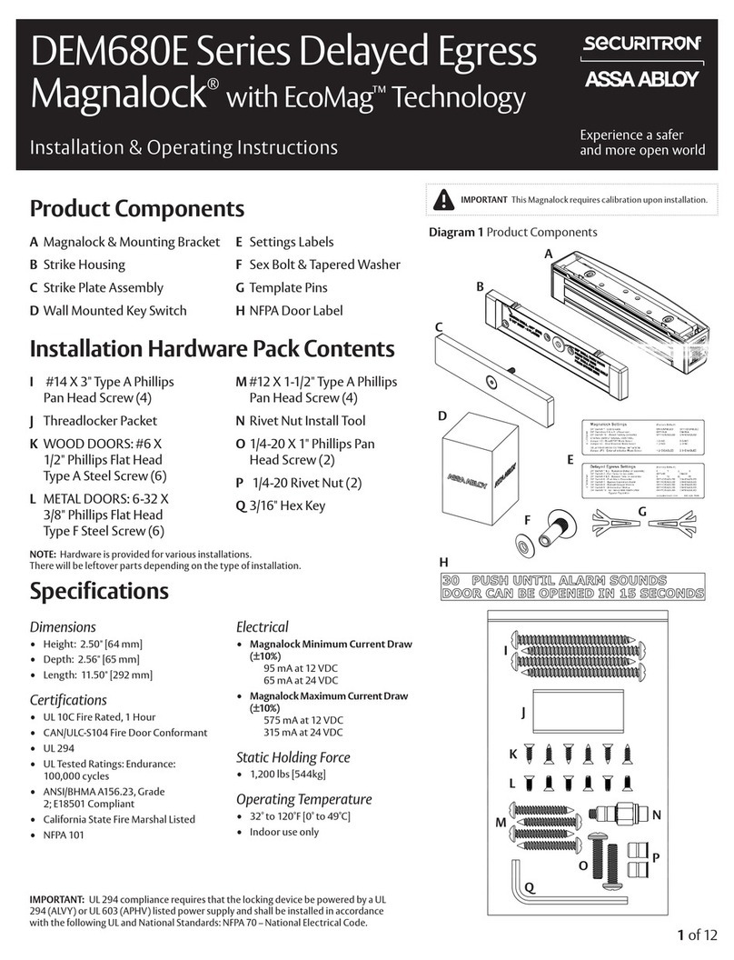
Assa Abloy SECURITRON DEM680E Series Installation & operating instructions
Assa Abloy
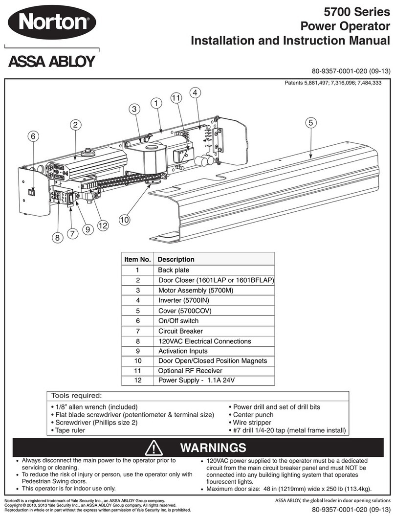
Assa Abloy Norton 5700 Series Installation and instruction manual
Detex
Detex Advantex 10 Series Maintenance manual
GEZE
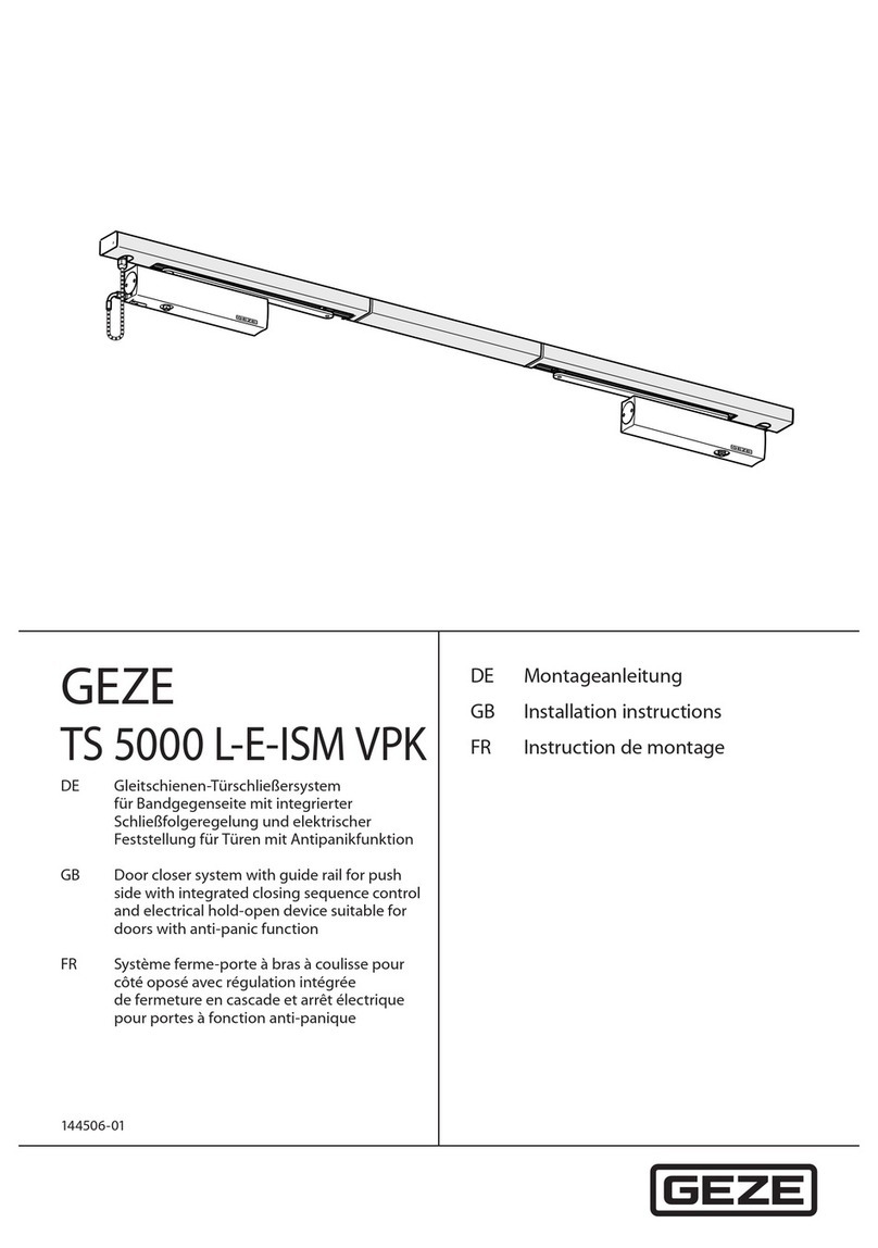
GEZE TS 5000 L-E-ISM VPK installation instructions
CAME
CAME 803XA-0320 instructions
Assa Abloy
Assa Abloy Norton LEO 5700 Series instructions

Dorma
Dorma TS 99 FLR Fixing instructions
Assa Abloy
Assa Abloy SARGENT 351 POWERGLIDE Series Instructions for installing
