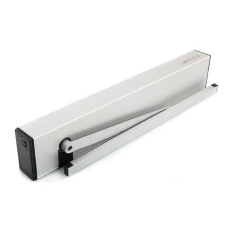
GILGEN SLX User manual

0635-999/06p
2017.12
Automatic sliding door
SLX
Operator manual
Original
Com. no. ............................................. Pos. .............................. Construction year ...............
Operator ..............................................................................................................................................
Operating place ........................................................................................................................................

SLX
0635-999-05---08p_2017.12.indd 0635-999/06p
Page 2 of 30
Operator manual
TABLE OF CONTENTS
1 GENERAL REMARKS .................................................................................................4
1.1 Target group.......................................................................................................4
1.2 Where to keep the operator manual ..................................................................4
1.3 Adresses............................................................................................................4
2 SAFETY .......................................................................................................................5
2.1 Appropriate use .................................................................................................5
2.2 Safety notices ....................................................................................................5
2.3 Safety regulations ..............................................................................................5
2.3.1 Principles..............................................................................................5
2.3.2 Service..................................................................................................6
2.3.3 Safety devices ......................................................................................6
2.3.4 Malfunctions .........................................................................................6
2.3.5 Accessories/Spare parts.......................................................................6
2.3.6 Slidingwingsandxedsidepanels......................................................6
3 PRODUCT DESCRIPTION..........................................................................................7
3.1 General remarks ................................................................................................7
3.2 Normal operation ...............................................................................................8
3.3 Options ..............................................................................................................8
3.3.1 Emergency battery ...............................................................................8
3.3.2 BAT-NOT-X...........................................................................................8
3.3.3 SLX-Redundant....................................................................................9
3.3.4 EMERGENCY STOP button.................................................................9
3.3.5 Locking of the running carriage LAVERI + LAVERI-FS ......................10
3.3.6 Locking/Manual unlocking .................................................................. 11
3.3.7 Multi-point locking FLUVERI...............................................................12
3.4 Control elements..............................................................................................13
3.5 Safety devices .................................................................................................13
3.5.1 Reversing and stopping mechanism ..................................................13
3.5.2 Limitation of the force .........................................................................13
3.6 Technical data..................................................................................................14
4 CONTROL..................................................................................................................15
4.1 D-BEDIX (option) .............................................................................................15
4.1.1 Keys....................................................................................................15
4.1.2 Symbols..............................................................................................15
4.1.3 Operating modes................................................................................16
4.1.4 Display of the door position ................................................................16
4.1.5 Menu level ..........................................................................................17
4.1.6 Settingexamples................................................................................18
4.1.7 Error display .......................................................................................19
4.2 KOMBI-D-BEDIX (option) ................................................................................20
4.3 C-BEDIX (option) .............................................................................................21
4.3.1 Operating mode keys .........................................................................21
4.3.2 Error display .......................................................................................21
4.3.3 Carrying out a Reset...........................................................................21
4.3.4 Switching over between winter and summer setting ..........................21
4.3.5 Blocking of keys..................................................................................21
4.4 KOMBI-C-BEDIX (option) ................................................................................22
4.5 BEDiX (option) .................................................................................................22
4.6 F-KEY (option) .................................................................................................22

SLX
0635-999-05---08p_2017.12.indd 0635-999/06p
Page 3 of 30
Operator manual
5 SERVICE ...................................................................................................................23
5.1 Care/checking to be carried out by the operator..............................................23
5.1.1 Switching off .......................................................................................23
5.1.2 Care....................................................................................................23
5.1.3 Checking.............................................................................................24
5.2
Maintenance/checking carried out by the after-sales service........................................24
6 TROUBLESHOOTING...............................................................................................25
6.1 With D-BEDIX / KOMBI-D-BEDIX / BEDiX ......................................................25
6.1.1 Error display .......................................................................................25
6.1.2 Carrying out a Reset...........................................................................25
6.2 With C-BEDIX / KOMBI-C-BEDIX....................................................................25
6.2.1 Error display .......................................................................................25
6.2.2 Carrying out a Reset...........................................................................25
6.3 Irregular functioning without error no. ..............................................................26
7 SHUT-DOWN.............................................................................................................27
8 DISPOSAL OF THE INSTALLATION.........................................................................28
9 SETTINGS MADE BY THE AFTER-SALES SERVICE..............................................29
10 APPENDIX.................................................................................................................30
• Declaration of incorporation according to machinery directive SLX ........................30
• Declaration of incorporation according to machinery directive SLX-Redundant .....30
• Declaration of conformity according to machinery directive SLX.............................30
• Declaration of conformity according to machinery directive SLX-Redundant..........30

SLX
0635-999-05---08p_2017.12.indd
!
0635-999/06p
Page 4 of 30
Operator manual
1 GENERAL REMARKS
The following documents are associated with this installation:
• Operating instructions 0635-999/26 onto the installation
• Operator manual 0635-999/06 by the operator
• Control booklet 0635-999/10 onto the installation
The present operator manual contains all the instructions needed for operation, mainte-
nance as well as troubleshooting and is the basis for a faultless and safe operation of the
installation.
The operator manual must be completely read and understood!
1.1 Target group
All the activities described in the operator manual may only be carried out by the operator
or by appropriately instructed persons!
1.2 Where to keep the operator manual
The operator manual is handed over to the operator who has to keep it at an easily ac-
cessible place.
Handed over to the operator Date ...............................
Signature ...............................
1.3 Adresses
Distribution agent/
After-sales service
Manufacturer Gilgen Door Systems AG
Freiburgstrasse 34
CH-3150 Schwarzenburg
Phone +41 31 734 41 11
Fax +41317344379
www.gilgendoorsystems.com

SLX
0635-999-05---08p_2017.12.indd 0635-999/06p
Page 5 of 30
Operator manual
2 SAFETY
2.1 Appropriate use
The door drive mechanism SLXhasbeenexclusivelydesignedforoperatingsliding
wings. Any other use beyond these application limits is deemed inappropriate and inad-
missible!
The door drive unit SLX-Redundanthasbeenexclusivelydesignedforoperatingsliding
wings in escape and rescue ways.
The term "redundancy" generally refers to a function which is carried out by two functional
elements. Only one element is required for ensuring this function. The second element
onlytakesoverintheeventofafailureoftherstelement.
In the event of an inappropriate use of this system, the safety of the user may be jeopar-
dized and/or the installation be damaged. The manufacturer declines all responsibility for
these injuries/damages!
2.2 Safety notices
The present instructions uses the following symbols and notes in order to point out certain
residual dangers:
Warning:
Involving danger to life and limb.
Attention:
A situation where material could be damaged or the function impaired.
Note:
Hints which facilitate the work.
2.3 Safety regulations
2.3.1 Principles
• The installation has been calculated, designed and manufactured on the basis of the
latest state-of-the-art technology and the generally recognized safety-relevant rules and
regulations. It may only be operated if it is in perfect condition, taking into account the
specicationsofthepresentmanual.Anyusebeyondthedenedapplicationlimitsis
inadmissible!
• The installation is to be operated and maintained in such condition that the safety is
guaranteed at all times. An integral part of this condition is the appropriate use, the
compliance with the operating conditions prescribed by the manufacturer, as well as the
regular service (maintenance/checking).

SLX
0635-999-05---08p_2017.12.indd 0635-999/06p
Page 6 of 30
Operator manual
• In order not to create any dangerous squeezing and shearing points, no structural mo-
dicationmustbemadewithinthedoorsurroundings,withoutpriorauthorizationfrom
Gilgen. Furthermore, it is important that no objects (such as furniture, pallets, etc.) be
placed in the vicinity of the door.
• Allfurtherinterventionsonandmodicationsoftheinstallationthatarenotdescribedin
the present instructions are forbidden!
• For doors used in escape and rescue ways, any obstruction of the opening movement
must be avoided, otherwise the escape and rescue route would no longer be fully gua-
ranteed. The required minimum width of the escape way must be complied with at all
times!
2.3.2 Service
In order to guarantee the safety of the users at all times, the installation must be checked
withregardtoitssafeconditionbeforetherstcommissioningandduringnormalopera-
tion, at least once a year, by a competent specialist. The correct maintenance/checking
mustbeconrmedbyenteringthedateandsignatureintothecontrolbooklet.
For installations used in escape and rescue ways, we recommend to carry out the service
at least twice a year.Thedatewhenthenextcheckingserviceisdueshallbespecied
on the monthly service sticker.
2.3.3 Safety devices
It is inadmissible to bypass, shunt or disable the safety devices. Any defective safety
devices may not be disconnected in order to be able to continue the operation of the
installation.
2.3.4 Malfunctions
If any malfunctions occur which might be detrimental to the safety of the users, the instal-
lation must be immediately taken out of operation. It may only be taken back into operati-
on after the malfunction has been repaired and all danger eliminated.
2.3.5 Accessories/Spare parts
A safe and reliable function of the installation can only be guaranteed if it is operated with
the original Gilgen accessories/spare parts. Gilgen declines all responsibility for damages
resultingfromunauthorizedmodicationsoftheinstallationorfromtheuseofforeign
accessories/spare parts.
2.3.6 Slidingwingsandxedsidepanels
Transparentsslidingwingsandxedsidepanels(ortheirsurfaces)mustbeclearlyreco-
gnizable, e.g. by means of a permanent marking or dyed materials.

SLX
0635-999-05---08p_2017.12.indd
A
B
C
D
E
F
G
H
I J
0635-999/06p
Page 7 of 30
Operator manual
3 PRODUCT DESCRIPTION
3.1 General remarks
The door drive mechanism SLX allows an automatic opening and closing of sliding doors.
The operating characteristics of the door can be determined via a control element (selec-
tion of the operating modes and setting of their respective parameters).
A sliding door installation may consist of the elements designated hereafter:
A Door drive mechanism F Push-button*
B Manual unlocking* G D- or C-BEDIX* Control element
C Side panel* H BEDiX* Control element
D Sliding wing I COMBI-SCAN INT Detector
E Key-operated pivoting switch* J COMBI-SCAN EXT Detector
* Option

SLX
0635-999-05---08p_2017.12.indd 0635-999/06p
Page 8 of 30
Operator manual
3.2 Normal operation
The door opening is performed automatically via impulse generator or manually by means
of a push-button. The door is automatically closed as soon as the programmed hold-open
timehasexpired.
In the event of a mains failure, the door remains blocked in the position in which it was
when the mains failure occurred. If the door was unlocked or open at that time, the sliding
wings can be moved by hand. If the door was locked, it is necessary to actuate the ma-
nual unlocking mechanism before the sliding wings can be moved (see chapter "Manual
unlocking"). As soon as the mains power supply has been restored, the drive unit resu-
mes its normal operation (after a slow-speed opening or closing run).
3.3 Options
3.3.1 Emergency battery
With the emergency battery, the door con-
tinues to function normally during 15...30
min. after a mains failure has occurred. As
soon as the emergency battery voltage has
droppeddowntotheexhaustivedischarge
limit, the door performs one last opening or
closing movement (depending on the basic
setting). Then the installation is automatical-
ly switched off.
If a power failure occurs while the installation is in the NIGHT operating mode, it is imme-
diately and automatically switched off. This prevents the emergency battery from reaching
its capacity limit in the event of a prolonged power failure.
3.3.2 BAT-NOT-X
Installations with a built-in BAT-NOT-X are especially used in France. The standards ap-
plicable in this country require the door to carry out a mechanical emergency opening in
the event of a power failure. This is ensured by the emergency opening rubber cable. The
door remains open until the mains power supply has been restored.
Theemergencybatteryoffersadditionalsafetyforareliablelastopeningprocedure.Ex-
ception: if the door is locked (i.e. in the operating mode NIGHT).
Note:
In cases where no emergency battery is provided, every time the selector switch
is switched from the operating mode NIGHT to another operating mode, a BAT-
NOT-X-Test is automatically carried out (the slidings wings are opened by 5...10
cm and re-closed).

SLX
0635-999-05---08p_2017.12.indd
0635-999/06p
Page 9 of 30
Operator manual
3.3.3 SLX-Redundant
The SLX-Redundant is used in escape and rescue ways. For redundant doors, a COMBI-
SCAN (incl. tested radar) in the direction of the escape way is mandatory. This radar must
be effective over the entire width of the door (from any point up to at least 1,5 m in front of
the door).
The SLX-Redundant arrangement includes two motors MOGET, one control unit NESTE-
RED and one emergency battery BATPA. The drive unit is failsafe, which means: If an
error occurs, or in the event of a mains power failure, the door must open and remain
in the open position in the operating modes MANUAL, OPEN, AUTOMATIC and EXIT
(ESCAPE WAY).
In the operating mode NIGHT the door remains closed and locked (NO ESCAPE WAY).
The door can be opened by means of the manual unlocking mechanism. Due to the fact
that the escape way function is disabled when the door is switched over to the program
position NIGHT, the program switch must be protected against unauthorized switching.
3.3.4 EMERGENCY STOP button
Installation depending on the regulations va-
lid in the country of application. An actuation
of the EMERGENCY STOP button causes
the sliding wings to stop immediately. They
can then be manually moved.
The EMERGENCY STOP button is generally
located inside (on the left) of the lower side
of the drive case. The EMERGENCY STOP
button is released by turning it shortly to the
right.
Warning:
The EMERGENCY STOP button must be easily visible and accessible at all
times. For redundant installations or installations with BAT-NOT-X, an actuation
of the EMERGENCY STOP button causes the door to be opened (because of
the escape and rescue way function).
Note:
An actuation of the EMERGENCY STOP button will be displayed by means of a
POP UPmessage on the BEDiX (option).

SLX
0635-999-05---08p_2017.12.indd 0635-999/06p
Page 10 of 30
Operator manual
3.3.5 Locking of the running carriage LAVERI + LAVERI-FS
The locking of the running carriage is mounted in the drive mechanism (within the area
of the closing edge). It features two interfaces where the Bowden cables of two manual
unlocking mechanisms can be connected.
The locking latch resp. the locking hook is
engaged into the running carriage(s), thus
preventing the sliding wings from being
forced open.
LAVERI
The locking is bistable, e.g. the locking latch
is held independently in the locked and
unlocked position. The locking state is not
conrmed.Correctlockingisnotchecked!
Behaviour in the event of a mains and batte-
ry failure:
Door position
closed locked
open unlocked
moving unlocked
closed locked
manuallly unlocked
manually opened
LAVERI
remains locked
remains unlocked
remains unlocked
is automatically locked upon manual clo-
sing
Behaviour in the event of a mains and batte-
ry failure:
LAVERI-FS
The locking mechanism is mono-stable, i.e.
the locking hook is electrically maintained
only in one position, while it automatically
drops into the other position in the event of
a mains failure. Whether the locking mecha-
nism is locked or unlocked without mains
power is determined by the way in which the
magnet has been installed.
Locking latch
Locking hook
Door position
closed locked
open unlocked
moving unlocked
Fail Safe
unlocked
Door remains closed.
unlocked
Door remains open.
unlocked
Door slows down to a full
stop.
Fail Secure
remains locked
Door remains closed.
locked
After being manually
closed, the door is locked.
locked
Door slows down to a full
stop.
After being manually
closed, the door is locked.

SLX
0635-999-05---08p_2017.12.indd
KABA 1514 –
SEA 1.043.0 –
DOM 2222Hix-5 333Hix-5
ZEISS-IKON – 0040
– 5040
– 5532 (L = 40 mm)
KESO 11.014.045 21.214.040
21.014.145 –
31.014.045 –
BKS – 3101 NBL31
– 3301 NBL31
– 8900 NBL31
0635-999/06p
Page 11 of 30
Operator manual
3.3.6 Locking/Manual unlocking
In the event of an emergency or of a mains
failure (without the option emergency
battery), the closed door can be opened
by pulling the red manual unlocking resp.
remote manual unlocking while at the same
time pushing the sliding wings to the open
position.
If the door leads to a room without a second
access, a lockable remote manual unlocking
is mounted on the outside of the door.
Warning:
The manual unlocking mecha-
nisms must be easily visible and
accessible at all times.
Manual unlocking
internal
Lockable remote manual
unlocking
Remote ma-
nual unlok-
king
Thecylindermustbeequippedwithareversibledriver8x45°.
Cylinder type

SLX
0635-999-05---08p_2017.12.indd
1'050
957
0635-999/06p
Page 12 of 30
Operator manual
3.3.7 Multi-point locking FLUVERI
Manual wing locking
By means of a rotary-type knob or a key
(2 turns) the door can be locked and unlocked
from the outside as well as the inside.
Automatic wing locking
The door is automatically locked by the auto-
matic unit integrated in the sliding wing. In the
event of a mains power failure/dysfunction, the
locking mechanism can be manually operated
from inside as well as from outside, using the
rotary-type knob or a key (4 turns).
Unlocking lever (option)
Bymeansofa45°turn(intheopeningdirection
of the sliding wing), an opening of the door is
possible in any case.
Application with manual and automatic FLU-
VERI. In the event of an automatic FLUVERI,
the actuation of the lever generates an opening
command.
Operation
Warning:
Make sure that the key is not left in
the lock when the sliding door is being
operated: Risk of injuries!
Attention
The sliding door must not be operated
whiletheswingboltsareextended!
An error message will be displayed on
the BEDiX (option). This error can be
eliminated by unlocking the FLUVERI.
fromnishedoor

SLX
0635-999-05---08p_2017.12.indd 0635-999/06p
Page 13 of 30
Operator manual
3.4 Control elements
The possible control elements are:
• Internal motion detector
• Externalmotiondetector
• Wireless control unit
• Program selector key
• Program selector key with cylinder AUTOMATIC-NIGHT
• Program selector key with cylinder FREE-LOCKED
• Functional key
• Key-operated pivoting switch
• Push-button
3.5 Safety devices
The required safety elements must be installed in accordance with the EU directives as
well as with the safety regulations valid in the country of application.
Attention:
We advise to use safety elements from the Gilgen product range. Gilgen cannot
assume any functional guarantee if elements from other suppliers are being
used!
the possible safety elements are:
• Internal motion detector Protection of the main and secondary closing edge
• Externalmotiondetector Protectionofthemainandsecondaryclosingedge
• EMERGENY-STOP button Stops the movement of the sliding wing
• Manual unlocking Emergency opening (if a locking is installed)
3.5.1 Reversing and stopping mechanism
If the sliding wings meet an obstacle during the closing process, the drive unit immediate-
lystopsandreopensthewings.Forreasonsofpersonalsafety,thenextclosingattempt
is performed after 3 seconds with reduced speed from the point where the obstacle had
been detected.
If the door touches an obstacle during the opening procedure, it is immediately stopped.
Forreasonsofpersonalsafety,thenextopeningattemptisperformedwithreduced
speed from the point where the obstacle had been detected.
3.5.2 Limitation of the force
The static driving power is limited to 150 N.
If the sliding wings are not protected by means of a fan-beam feeler/a protection wing
(depending of risk evaluation, directives, prescriptions), this protection is achieved by a
limitation of the dynamic forces of the sliding wing.

SLX
0635-999-05---08p_2017.12.indd 0635-999/06p
Page 14 of 30
Operator manual
3.6 Technical data
Power transmission Toothed belt
Number of revolutions
toothed belt pulley 40...330 min-1
Operating voltage 230 VAC (+6 %/-10 %), 50...60 Hz
115 VAC (+6 %/-10 %), 50...60 Hz
Control voltage 24 VDC (1 A)
Powerconsumption max.280W
Ambienttemperature -15...+50°C
if the installation remains permanently connected to the
mains supply
The unit may only be
usedindryrooms max.relativehumidity70%
Protection type IP 23

SLX
0635-999-05---08p_2017.12.indd 0635-999/06p
Page 15 of 30
Operator manual
4 CONTROL
4.1 D-BEDIX (option)
The different operating modes can be
directly enabled by means of the D-BEDIX.
In addition, it provides easy programming of
the most important door settings.
The operating modes, menu settings as well
as possible errors are displayed in a clearly
arranged synopsis.
Only one D-BEDIX can be connected per
door installation.
4.1.1 Keys
C-key (Cancel)
• Exitthemenu
• Invalidate entry
OK-key
• Conrmtheselection
• Conrmtheentry
Arrow keys
• Navigate within the menus
• Short simultaneous actuation of both keys = acces to the menu level
4.1.2 Symbols
Opening width
• Winter = reduced opening width
• Summer = complete opening width
Operating mode symbols
• Show the possible operating modes
(see chapter: Operating modes)
Selection frame (active and preselected operating mode)
• Shows what has been presently selected.
Selection frame (active operating mode)
• Shows what has been presently selected but is still inhibited. A control ele-
ment with higher priority (e.g. key-operated switch) determines the operating
mode.
Bar (preselected operating mode)
• Shows the preselected operating mode.

SLX
0635-999-05---08p_2017.12.indd 0635-999/06p
Page 16 of 30
Operator manual
4.1.3 Operating modes
With the D-BEDIX, the following operating modes can be selected by means of the corre-
sponding symbols:
AUTOMATIC
Automatic operation (summer or winter opening width). The installation is not
locked.
NIGHT
The installation is locked*. As opening commands, only the key-operated impul-
se switch or the F-KEYs (with key function) are accepted.
The delayed switchover to the operating mode NIGHT can be activated by
means of parameter Tvn. Function: If the program selector switch is changed to
the operating mode NIGHT from any random operating mode, the internal radar
will still remain active during the programmed time Tvn (EXIT). Tvn is not active
in escape and rescue ways.
Attention:
For installations used in escape and rescue ways, it is necessary in addition to
install a key-operated switch (for switching-over from AUTOMATIC to NIGHT),
to make sure that only duly authorized persons can switch over to the NIGHT
position (= disabling of the escape way).
OPEN
The installation is opened and remains in the open position.
MANUAL
The installation stops. The sliding wings are released and can be shifted by hand.
EXIT
One-waytrafcfrominsidetowardstheoutside.
The installation is locked* (shop closing switching mode).
For installations used in escape and rescue ways, the door is unlocked. The
escape way function is maintained.
* Provided that the locking mechanism (optional) is installed.
4.1.4 Display of the door position
The following door positions are represented onthe D-BEDIX display:
Closed and locked*
Closed
Opening
Closing
Open
* Provided that the locking mechanism (optional) is installed.
• LAVERI standard = position of locking latch not monitored.
• LAVERI F+R = position of locking latch monitored.
>> <<
< >
<< >>
><
>##<

SLX
0635-999-05---08p_2017.12.indd
Kundendienst benachrichtigen = Unterschied zu BA
RESET?
To ?
Tn ?
Tvn ?
s ?
Vo ?
Vc ?
VERS ?
CYCLE?
LOCK ?
UNLOC?
T LCD?
0...45 s (Standard 1 s)
0...45 s (Standard 5 s)
0...90 s
10**...100 %
50...800* mm/s
50...800* mm/s
0...300 s
Display
0635-999/06p
Page 17 of 30
Operator manual
4.1.5 Menu level
Short and simultaneous actuation of both arrow keys (=access to the menu level).
Select the desired menu item bymeans of the arrow key.
ConrmbymeansoftheOKkey.
* Note:
Dependingonthewingweight,themaximumvalueswillbereducedbythe
system.
** Attention:
For installations used in escape and rescue ways, the reduced opening width
must still answer the minimum escape way width requirement! If in doubt about
this width, please contact the responsible building owner or architect.
Program the "Threshold value sOpening" via the BEDiX (contact the after-sales
service).
Description
Winter (reduced opening width)
Summer (entire opening width)
New setting-up of the drive unit
Hold-open time Day
Hold-open time Night
Delay time for switching-over to Night
Reduced opening width (winter)
Opening speed
Closing speed
Software version
Number of opening cycles
Enable the keylock
Disable the keylock
Background lighting
Setting range

SLX
0635-999-05---08p_2017.12.indd
?
LOCK ?
UNLOCK
0635-999/06p
Page 18 of 30
Operator manual
Summer opening / winter opening
Short simultaneous actuation of the arrow keys (= access to the menu level).
ConrmthechangebymeansoftheOKkey.
Disabling the keylock
Short simultaneous actuation of the C-key and the right-hand arrow key.
Short simultaneous actuation of the arrow keys (= access to the menu level).
By means of the arrow key, select UNLOCK.
ConrmwiththeC-keyandtheright-handarrowkey.
Temporarily disabling the keylock (60 s)
Short simultaneous actuation of the C-key and the right-hand arrow key.
Enabling the keylock
Short simultaneous actuation of both arrow keys (= access to the menu level).
By means of the arrow key, select LOCK.
ConrmwiththeC-keyandtheright-handarrowkey.
4.1.6 Settingexamples
Changing the operating mode
Selectthedesiredsymbolbymeansofthearrowkey(symbolstartsashing).
ConrmwiththeOKkey(frame/barswitchover).
Preselecting the operating mode
An overriding switch is active and determines the operating mode (only the selection fra-
me is visible, the bar underlines the preselected operating mode). Now you can select the
operating mode you want to be active upon cancellation of the overriding switch:
Selectthedesiredsymbolbymeansofthearrowkey(symbolstartsashing).
ConrmwiththeOKkey(barswitchesover).

SLX
0635-999-05---08p_2017.12.indd
Kundendienst benachrichtigen = Unterschied zu BA
ERROR: E 7O3 END
RESET?
7
To ?
0635-999/06p
Page 19 of 30
Operator manual
Parameters (hold-open timeday)
Short simultaneous actuation of the arrow keys (= access to the menu level).
By means of the arrow key, select To.
ConrmwiththeOKkey.
By means of the arrow key, change the value.
ConrmwiththeOKkey.
Reset
Short simultaneous actuation of the arrow keys (= access to the menu level).
By means of the arrow key, select Reset.
ConrmwiththeOKkey.
4.1.7 Error display
As soon as an error occurs, the mention ERROR appears on the display, followed by
the number of the presently active error (e.g. E 703).
Provided that no additional error is pending, END is displayed (error list: see chapter
Troubleshooting).
This sequence will be repeated until the error has been eliminated.
Display-Reset D-BEDIX
Keep the C key depressed during 3 seconds.
D-BEDIX is restarted (however, the setting-up procedure of the door is not repeated).

SLX
0635-999-05---08p_2017.12.indd 0635-999/06p
Page 20 of 30
Operator manual
4.2 KOMBI-D-BEDIX (option)
In addition to the functions of the D-BEDIX,
the KOMBI-D-BEDIX contains a key-opera-
tedswitch(roundorprolecylinder)withthe
following functions:
• Switching-over from AUTOMATIC to
NIGHT (disabling of the escape way func-
tion for doors used in escape and rescue
ways).
Escape way for: No escape way:
MANUAL NIGHT
AUTOMATIC
EXIT
OPEN
• Lockout of the KOMBI-D-BEDIX against
unauthorized use.
Free Locked
Round cylinder Prolecylinder
KABA 1514
SEA1.043.0
DOM2222Hix5
Driver with 8 adjusting possi-
bilities
KESO 11.014.045
KESO 21.014.045
KESO 31.014.045
Adjustable beard E 201
KESO 21.214.040
Adjustable beard E 200
DOM333ix-5
Driver with 8 adjusting possi-
bilities
BKS 8900 N BL 31
BKS 3101 N BL 31
BKS 3301 N BL 31
ZEISS IKON 0040
ZEISS IKON 5040
ZEISS IKON 5044
ZEISS IKON 6044
ZEISS IKON 7044
Cylinder = supplied by customer
Table of contents
Other GILGEN Door Opening System manuals
Popular Door Opening System manuals by other brands

Siemens
Siemens 3VL9800-3A 0 Series operating instructions

Allstar
Allstar J & H Series owner's manual

GFA
GFA ELEKTROMAT KE 120.30 FU-55,00 installation instructions

Dorma
Dorma 900S Series installation instructions

Scrigno
Scrigno MAGNIFICO manual

HOMEBUILDERS HARDWARE
HOMEBUILDERS HARDWARE LAWRENCE HARDWEAR 8016 Series Installation instruction