Nellcor NPB-75 User manual

SERVICE MANUAL
NPB-75 Handheld Capnograph / Pulse Oximeter
Caution: Federal law (U.S.) restricts this device to sale by or on the order of a physician.
To contact Mallinckrodt, Inc. representative: In the United States, call 1-800-635-5267: outside the United States,
call your local Mallinckrodt representative.
© 2001 Mallinckrodt Incorporated. All rights reserved. 061222B-0601

Nellcor Puritan Bennett Inc. is a wholly owned subsidiary of Mallinckrodt, Inc.
To obtain information about a warranty, if any, for this product, contact Mallinckrodt Technical Services or your local Mallinckrodt representative.
Purchase of this instrument confers no express or implied license under any Mallinckrodt patent to use the instrument with any sensor that is not
manufactured or licensed by Mallinckrodt.
Nellcor Puritan Bennett, Nellcor, Durasensor, and Oxisensor II, are trademarks of Mallinckrodt Incorporated.
Covered by one or more of the following U.S. Patents and foreign equivalents: 4,621,643; 4,653,498; 4,700,708; 4,770,179; 4,869,254; 5,078,136;
5,351,685; and 5,368,026.
Nellcor Puritan Bennett Inc.
4280 Hacienda Drive
Pleasanton, CA 94588 USA
Telephone Toll Free 1.800.NELLCOR
Tyco Healthcare UK LTD
Fareham Road
Gosport
PO13 0AS
U.K.
Tel: +44.1329.224000

Handheld Capnograph/Pulse Oximeter
Service Manual
005554B

(This page intentionally left blank)

TABLE OF CONTENTS
List of Figures
List of Tables
Section 1: Introduction........................................................................1-1
1.1 Manual Overview...............................................................1-1
1.2 Warnings, Cautions, and Notes.........................................1-1
1.2.1 Warning..............................................................1-1
1.2.2 Caution...............................................................1-1
1.2.3 Note....................................................................1-1
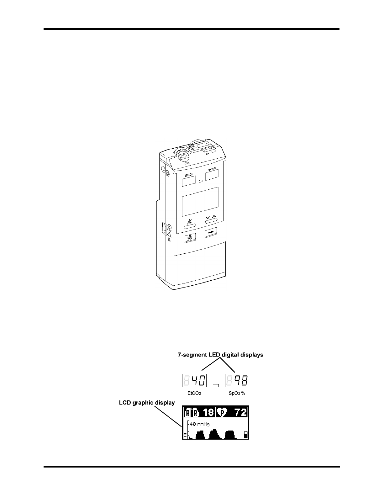
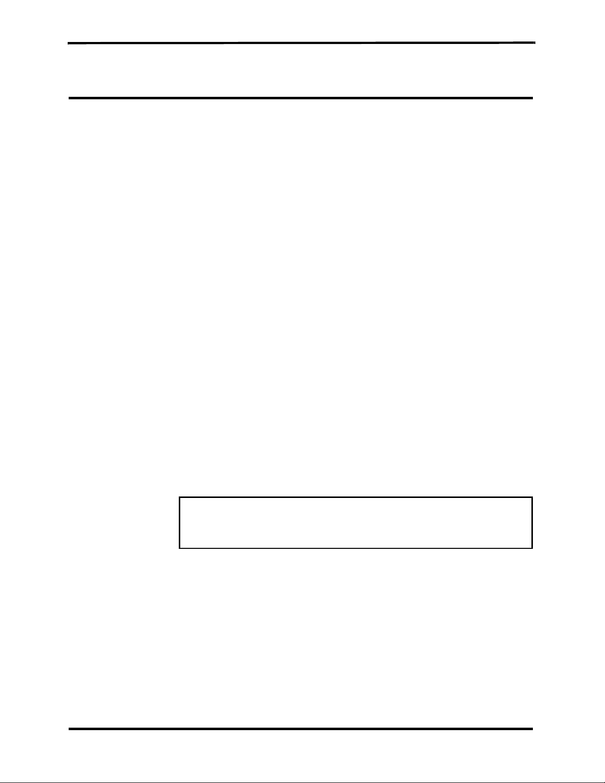
1.3 Product Description ...........................................................1-2
Section 2: Required Equipment
..........................................................2-1
2.1 Required Equipment..........................................................2-1
Section 3: Cleaning
...........................................................................3-1
3.1 Cleaning ...........................................................................3-1
3.1.1 Procedure...........................................................3-1
Section 4: Service Mode
......................................................................4-1
4.1 Introduction........................................................................4-1
4.2 Service Level 1..................................................................4-1
4.2.1 Information Screen.............................................4-1
4.2.2 Event Messages Screen....................................4-1
4.2.3 Interface Test Screen.........................................4-2
4.2.4 Accessing Service Mode and Service Level 1...4-3
4.3 Service Level 2..................................................................4-5
4.3.1 Default Alarm Limits...........................................4-7
4.3.2 Default Settings..................................................4-9
4.3.3 Flow Calibration ...............................................4-10
Section 5: Troubleshooting
.................................................................5-1
5.1 Introduction........................................................................5-1
5.2 Who Should Perform Repairs............................................5-1
5.3 Repair Level Supported.....................................................5-1
5.4 How to Use This Section ...................................................5-1
5.5 Obtaining Replacement Parts............................................5-1
5.6 Troubleshooting Guide ......................................................5-2
Section 6: Flow Calibration Check.....................................................6-1
6.1 Introduction........................................................................6-1
6.2 Flow Rate Check ...............................................................6-1
6.3 Flow Calibration Process...................................................6-2
Section 7: Disassembly Guide
............................................................7-1
7.1 Introduction........................................................................7-1
7.2. Opening the Monitor Case.................................................7-2
7.3 Replacing the CO2Board ..................................................7-4
7.4 Replacing the SpO2Board.................................................7-5
7.5 Replacing the Pump ..........................................................7-6
7.6 Replacing the Flow System...............................................7-7
7.6.1 Replacing the lines to the pump.........................7-8
7.6.2 Replacing the lines to the solenoid ....................7-9
7.7 Replacing the LCD and LED Display...............................7-11
7.7.1 Replacing the LCD...........................................7-11
7.7.2 Replacing the LED Display ..............................7-11
iii

Table of Contents
7.8 Replacing the Housing Components...............................7-12
7.8.1 ON/OFF Button and Gas outlet........................7-12
7.8.2 Keypads...........................................................7-12
7.8.3 Front Cover......................................................7-13
7.8.4 SpO2Connector Latch, Rear Cover and
SpO2Insulation Plate.......................................7-13
7.9 Updating the Software Version........................................7-14
Section 8: Electrical Safety Tests.......................................................8
-1
8.1 Electrical Safety Tests.......................................................8-1
Section 9: Periodic Maintenance........................................................9-1
9.1 Periodic Maintenance........................................................9-1
Section 10: Performance Verification...............................................10-1
10.1 Flow System Leak Check................................................10-1
10.1.1 Flow System Leak Check Procedure...............10-1
10.2 Performance Verification Procedure................................10-2
Section 11: Packing For Shipment ...................................................11-1
11.1 General Instructions.........................................................11-1
11.2 Packing the Monitor in Original Carton............................11-1
11.3 Packing in a Different Carton...........................................11-1
Section 12: Specifications
.................................................................12-1
12.1 Physical .........................................................................12-1
12.1.1 Size..................................................................12-1
12.1.2 Weight..............................................................12-1
12.1.3 Noise Emission ................................................12-1
12.2 Environmental..................................................................12-1
12.2.1 Temperature.....................................................12-1
12.2.2 Relative Humidity.............................................12-1
12.2.3 Pressure and Altitude.......................................12-1
12.3 Safety Standards.............................................................12-1
12.4 Performance....................................................................12-2
12.4.1 Capnograph .....................................................12-2
12.4.2 Pulse Oximeter.................................................12-3
12.5 Power Specifications .......................................................12-4
12.5.1 External Power Source ....................................12-4
12.5.2 Internal Power Source......................................12-4
12.6 Components and User interface......................................12-4
12.6.1 Displays............................................................12-4
12.6.2 Controls and Indicators....................................12-4
12.6.3 Connections.....................................................12-4
Section 13: Spare Parts
.....................................................................13-1
13.1 Spare Parts List...............................................................13-1
Glossary of Terms
iv

Table of Contents
LIST OF FIGURES 1-1 Handheld Capnograph/Pulse Oximeter.............................1-2
1-2 LCD Graphic Display Screen and
7-Segment Digital Display .................................................1-2
7-1 Removing the Battery Pack...............................................7-2
7-2 Removing Mounting Screws..............................................7-3
7-3 Separating Rear and Front Covers....................................7-3
7-4 Replacing CO2Board and Housing Components..............7-4
7-5 Replacing SpO2Board.......................................................7-5
7-6 Replacing the Pump ..........................................................7-6
7-7 Flow System......................................................................7-7
7-8 Main Line...........................................................................7-8
7-9 Exhaust Line......................................................................7-8
7-10 Lines to Solenoid (Zero line, Input line 1, Input line 2........7-9
7-11 Zero line...........................................................................7-10
7-12 Replacing LCD and LED Display.....................................7-11
7-13 Replacing SpO2Connector Latch....................................7-13
7-14 Replacing EPROM...........................................................7-14
10-1 Leak Test Jig Connection................................................10-1
10-2 Initialization Screen..........................................................10-2
10-3 Self-Test Screen..............................................................10-2
10-4 Measuring Mode..............................................................10-2
10-5 Quick Guide.....................................................................10-3
10-6 Connecting the monitor to Printer/PC with
Communication Adapter Kit.............................................10-9
11-1 Packing the Monitor in Original Packing..........................11-2
LIST OF TABLES 4-1 Accessing Service Mode and Changing Parameter
Settings...................................................................4-3
4-2 Accessing Service Level 2.................................................4-5
4-3 Changing Default Alarm Limits..........................................4-7
4-4 Changing Default Settings.................................................4-9
4-5 Accessing Flow Calibration..............................................4-10
5-1 Troubleshooting Guide ......................................................5-2
5-2 Advisory Messages Guide.................................................5-4
5-3 Event Messages................................................................5-5
6-1 Flow Calibration.................................................................6-2
10-1 CO2Calibration Check.....................................................10-4
10-2 Calibration Process..........................................................10-6
10-3 Calibration Process -Troubleshooting..............................10-7
10-4 Plethysmograph Waveform .............................................10-8
10-5 Accessing Monitor’s Print Functions..............................10-10
13-1 Spare Parts List...............................................................13-1
v

SECTION 1: INTRODUCTION
1.1 Manual Overview
1.2 Warnings, Cautions, and Notes
1.3 Product Description
1.1 MANUAL OVERVIEW
This manual contains information for servicing the handheld capnograph/
pulse oximeter (the monitor). Only qualified service personnel should
service this product. The Handheld Capnograph/Pulse Oximeter
Operator’s Manual (the operator’s manual) is an integral part of the
service procedures. Before servicing the monitor, read the operator’s
manual carefully for a thorough understanding of how to operate the unit.
Only use the tools and test equipment as specified in this manual. Only
use original spare parts available from your local distributor.
Warning: Incorrect procedures may harm the patient, or
damage the monitor.
1.2 WARNINGS, CAUTIONS, AND NOTES
1.2.1 Warning
A warning precedes an action that may result in injury or death to the
patient or user. Warnings are boxed and highlighted in boldface type.
1.2.2 Caution
Acautionprecedesan action that may result in damage to,or malfunction
of, the monitor. Cautions are highlighted in boldface type.
1.2.3 Note
A note gives information that requires special attention.
1-1

Section 1: Introduction
1-2
1.3 PRODUCT DESCRIPTION
The handheld capnograph/pulse oximeter is used to continuously monitor
end-tidal carbon dioxide (EtCO2), respiratory rate, oxygen saturation
(SpO2), and pulse rate. The monitor is for attended monitoring only and
must be used in the continuous presence of a qualified healthcare
provider.Themonitorcan be used on adult, pediatric,andinfant/neonatal
patients. It is intended for use where continuous, noninvasive monitoring
of these parameters is desired, including hospital and mobile use (when
protected from excessive moisture such as direct rainfall). The monitor
operates on AC power or a rechargeable Nickel Metal Hydride battery
pack.
Figure 1-1: Handheld Capnograph/Pulse Oximeter
The monitor is operated using a four-key keypad. Measurements are
displayed on the front panel onthe 7-segment LED digital displays (LED)
andontheLCDgraphic display (LCD) as shown in Figure 1-2.Refertothe
operator’s manual for complete operating instructions.
Figure 1-2: LCD Graphic Display and 7-Segment Digital Displays

SECTION 2: REQUIRED EQUIPMENT
2.1 Required Equipment
2.1 REQUIRED EQUIPMENT
You will need the following equipment to disassemble, replace parts,
check, adjust, or calibrate the monitor.
For disassembly and replacement:
• Phillips-head screwdriver (medium)
• Flat-head screwdriver (small)
• IC Extractor for PLCC socket
• Threadlocker glue e.g. Loctite®222 super screw lock
For checks, adjustments and calibration:
• Calibration Gas (5% CO2in air)
• FilterLine or FilterLine H
• DS-100A - Durasensor®, Nellcor
• Leak Test Jig
• Vacuum manometer with a range of 0-500 mBar
e.g. MPB-3200-DM, Digital Manometer MicroPneumatic Logic, Inc.
• Communication Adapter Kit (only necessary to verify print functions)
• Seiko DPU-414 printer (only necessary to verify print functions)
• External power supply
• Handheld Capnograph/Pulse Oximeter Operator’s Manual
• Flow Meter (range 0-50 ml/min) e.g. Top Track Mass Flow Meter,
model: 822-13-OV1-PV1-V1, Sierra Instruments, Inc.
Warning: Observe ESD (electrostatic discharge) precautions
when handling, adjusting or performing any procedure with
the monitor’s internal components.
2-1

(This page intentionally left blank)

SECTION 3: CLEANING
3.1 Cleaning
3.1 CLEANING
Always clean the outer surface of the monitor before servicing.
Warning: Always wear latex or surgical gloves when cleaning
or servicing the monitor after hospital use.
Warning: Do not allow liquids to drip inside the housing.
Warning: Do not clean internal components.
Warning: Do not use preparations based on: phenols, halogen
producing compounds, strong organic acids, or oxygen
producing compounds.
3.1.1 Procedure
1. Unplug the unit from AC power.
2. With a damp cloth, gently wipe the outer case of the monitor with a
disinfectant based on aldehyde, alcohol or quaternary ammonium
producing compounds.
3-1

(This page intentionally left blank)

4-1
SECTION 4: SERVICE MODE
4.1 Introduction
4.2 Service Level 1
4.3 Service Level 2
4.1 INTRODUCTION
Themonitorsupports a service mode builtintotheinstrument’sfirmware.
To access the service mode, refer to Table 4-1: "Accessing Service Mode
and Changing Parameter Settings".
The architecture of the monitor’s service mode divides the service mode
into two levels as described in the sections below.
• Service Level 1
• Service Level 2
4.2 SERVICE LEVEL 1
The Service Level 1 provides information and tools on three service
screens to test and calibrate specific functions without disassembling the
monitor.
• Information Screen
• Event Messages Screen
• Interface Test Screen
From these display screens the service technician can check the operating
hours counter and event messages, test the Human Interface functions
(HMI), set the light detection threshold, adjust the LCD contrast middle
point and perform a calibration check and a calibration process, if
necessary. Refer to Table 4-1: "Accessing Service Mode and Changing
Parameter Settings".
4.2.1 Information Screen
The information screen displays the monitor’s main board serial number,
the number of operating hours, and the SpO2 and CO2boards’ software
versions.
4.2.2 Event Messages Screen
The monitor automatically performs a series of built-in tests (BITs) at
start-up and during operation to check sub-systems and modules for
errors. The event messages screen lists the last five event messages, the
time each occurred relative to the unit’s operating hours, and a
recommended service action. There are three event messages and each
has a specific response as follows:
Event Message: Action:
CO2board Replace CO2board
SpO2board Replace SpO2board
Flow Replace CO2board

Section 4: Service Mode
4-2
monitor. Event messages will be erased when exiting the service
mode by a long press of .
4.2.3 Interface Test Screen
The interface test screen shows four parameters (listed below) that
provide tools for the user to test, adjust, and calibrate the unit’s
interfacing systems.
• HMI Test
• Light Detector
• Contrast Cal. (Calibration)
•CO
2Calib. (Calibration)
4.2.3.1 HMI Test
When the HMI Test is turned on, the monitor performs a self-test of the
following sub-systems:
• Buzzer (sounds for one second)
• LCD graphic display (screen shows a checkerboard pattern)
• 7-segment digital display (8s scroll left to right)
• Alarm bar (lights red, yellow, off)
• Backlight (turns on and off)
• Alarm silence indicator (light turns on and off)
When the HMI test is completed, the status field returns automatically to
OFF.
4.2.3.2 Light Detector
The Light Detector parameter allows the service technician to set the
threshold value of the phototransistor. The default value is 1 and the
range is from 1 to 5 with 1 as the most sensitive (backlight on at all times)
and 5 as the least sensitive (backlight off). The threshold value should be
set according to the lighting conditions of the working environment. A
higher threshold value saves on battery power consumption.
4.2.3.3 Contrast Cal. (calibration)
The Contrast Cal. gives the service technician the option to change the
middle point default value of the contrast intensity of the LCD. Refer to
Table 4-1: "Accessing Service Mode and Changing Parameter Settings".
4.2.3.4 CO2 Calib. (calibration)
The CO2Calib. allows the service technician to perform a calibration
check and calibration process to ensure the accuracy of the monitor.
Section 10: Performance Verification describes the calibration check
procedure.
Note: To exit the service mode and save event messages, turn off the

4-3
Section 4: Service Mode
4.2.4 Accessing Service Mode and Service Level 1.
Table 4-1: "Accessing Service Mode and Changing Parameter Settings"
describes the process to access the service mode, change parameter
settings and how to change Contrast Cal. settings.
Table 4-1: Accessing Service Mode and
Changing Parameter Settings
Objective Action Response
To access Service Mode During self-test,
long press
simultaneously
and
Self-test occurs and the
Information Screen
appears:
To access Event
Messages screen long press
To access Interface
Test screen long press
To change the
parameter setting or
value
short press
To move to the next
parameter short press

Section 4: Service Mode
4-4
Objective Action Response
To change Contrast
Cal. setting to set short press
To start Contrast Cal. short press “Contrast Cal.” flashes.
To adjust Contrast
Cal. middle point press
until desired
setting is reached.
(Pressingon theleft
lightens the screen,
and pressing on the
right darkens the
screen.)
Screen lightens or
darkens
To accept new setting short press
To reset and return to
measuring mode
(automatically erasing
the event messages
memory)
long press
Note: Reset time is
approximately one
minute.
To exit service mode
from any service
screen without erasing
the event messages
memory
Turn off the
monitor.
Table 4-1: Accessing Service Mode and
Changing Parameter Settings (Continued)

4-5
Section 4: Service Mode
4.3 SERVICE LEVEL 2
The Service Level 2 gives the service technician tools on three service
screens:
• Default Alarm Limits
• Default Settings
• Flow Calibration
To access this service level, the service technician must enter a valid
password (1627), refer to Table 4-2: "Accessing Service Level 2".
Note: The password should not be disclosed to avoid unauthorized setting
of parameters.
Table 4-2: Accessing Service Level 2
Objective Action Response
To access
Service Level 2 After entering the
service mode
long press (x3)
Password Screen
appears
Enter Password: 1627
Enter the 1st digit short press (right)
(x1)
Pressing on the
right arrow scrolls
the numbers up,
the left arrow
scrolls the numbers
down.
Move to the next digit short press
Enter the 2nd digit short press (right)
x6
Repeat the same procedure as above for the next two digits (2, 7).

Section 4: Service Mode
4-6
Objective Action Response
To accept the last digit
and access the Default
Alarm Limits menu
short press
In case you entered a
wrong digit:
To restart password
validation process long press
To reset and return to
measuring mode
(automatically erasing
event messages)
long press
To exit service mode
and save event
messages
Turn off the
monitor.
Table 4-2: Accessing Service Level 2 (Continued)

4-7
Section 4: Service Mode
4.3.1 Default Alarm Limits
The service technician can change the default alarm limits for either
patient mode (Adult or Neonatal) as described in Table 4-3: "Changing
Default Alarm Limits".
The monitor has the following alarms with adjustable level settings:
•EtCO
2 high and low levels (mmHg)
•FiCO
2 high level (mmHg)
•SpO
2 high and low levels (%)
• Pulse rate high and low levels (bpm)
Warning: Changing default settings will permanently change the
user’s start-up value and should be verified with the responsible
clinical personnel.
Table 4-3: Changing Default Alarm Limits
Objective Action Response
To access the Default
Alarm Limits menu
after entering last
password digit
short press
To change the patient
mode short press
To access a new
parameter short press
To change the value short press
Table of contents
Other Nellcor Measuring Instrument manuals
Popular Measuring Instrument manuals by other brands

National
National SG -990A Service manual

Powell
Powell EcoVisor 01.41B.48080 Instruction bulletin

Apogee Instruments
Apogee Instruments SIF-111 owner's manual

Hioki
Hioki 9196 instruction manual

Etatron
Etatron eSelectM 2 PH-CL Operating instructions and maintenance

Greenlee
Greenlee TML-30 instruction manual