Nelson
Irrigation
Corporation
848
Airport
Rd.
Walla
Walla,
WA
99362-2271
USA
Tel:
509.525.7660
Fax:
509.525.7907
[email protected] Web
site:
www.nelsonirrigation.com
2/18
SR100 MAINTENANCE
SEE SR100 PARTS LISTS FOR COMPLETE PARTS LIST AND DESCRIPTION
DISASSEMBLY REASSEMBLY
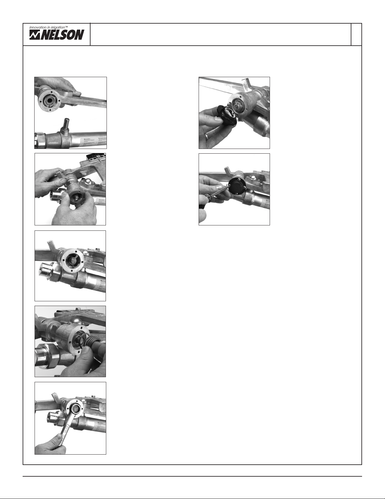
STEP 4 (Counterweight)
Inspect seal spacer and counter-weight
spacer for wear. If spacers show
excessive wear, replace both spacers
and #6600 Seals. To remove seals,
drive thin-bladed screwdriver under
lip of seal and pry seal out. To replace
seals, use block of wood over seal
making sure lip is to the outside, and
secure by lightly tapping on wooden
block until seal lip is flush with hub.
Apply a light coating of #9673 Silicone
Grease to #6600 Seal Lips.
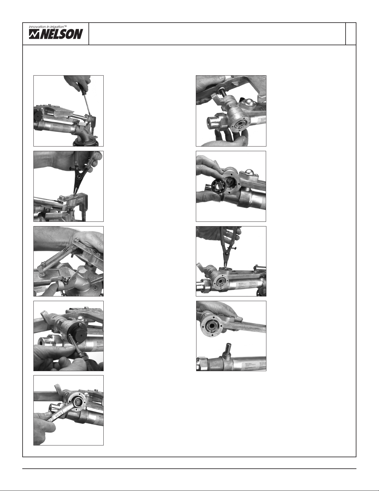
STEP 5 (Shift Lever)
Remove #10070-001 Cap Assem-
bly. Using external retaining ring
pliers, remove #8323-017 Retain-
ing Ring. Pull Shift lever from
mount. A gear puller will help in
removing the lever. Inspect all parts
for wear and replace as required.
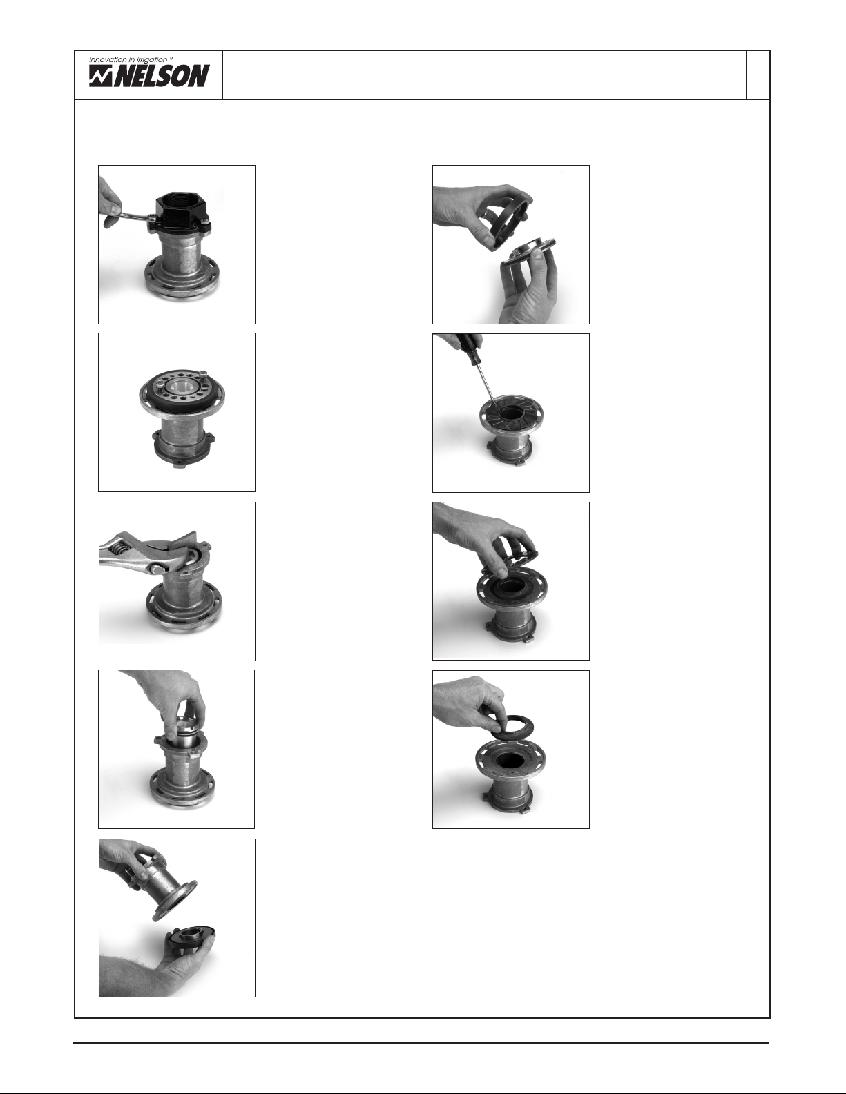
STEP 9
Fill two #10067-001 Arm Cap
Assemblies with #6143 Grease
and snap into place. Install two
#6565 Retaining Rings. Arm
must have free movement at this
point. If arm feels sticky, assure
that lip seals at counterweight and
right arm hub are not rubbing on
each other.
STEP 10 (Trip Lever)
Mount trip lever assembly along
with spring guide onto their
respective pins. Install #8323-004
Retaining Ring. Install #8263 Cap
using two #8311 Screws. Install
#8409 Washer and #6714 Cotter
Pin onto spring guide.
STEP 3
Using a thin-bladed screwdriver,
push #8327-001 Spacer back
into arm hub. Holding onto counter-
weight, remove drive arm and
counterweight. Be careful not to
damage seals.
STEP 8
Holding counterweight in place on the
left side of shift lever, roll drive arm
into position shown by pushing on the
left arm bearing. Work #8327-001
Spacer into seal on counterweight.
Be sure spacer is correctly positioned
in counterweight to prevent cutting of
the seal lip. Push shaft through the
bearings and spacers and assemble
#6603 Nut. Torque to 25 ft. lbs. using
two 11/16” sockets. (Metric Torque =
34 NM or 3.5 MKG.)
STEP 2 (Drive Arm)
Using internal retaining ring pliers,
remove #6565 Retaining Ring
from both arm hubs. Remove two
#10067-001 Arm Caps. Using two
11/16” sockets, loosen and remove
one #6603 Nut from left side of
arm. Holding the opposite #6603
Nut, pull shaft free from hub.
STEP 7 (Drive Arm)
Lubricate #6600 Seal lips with
#9673 Silicone Grease. Install
#8327-001 Spacer flush with
#6600 Seal in left arm hub.
Insert two #6607-001 conical
Spacers into seals on inside of
counterweight and right drive arm
hub. Start #8297 Shaft into right
arm hub.
STEP 1 (Trip Lever)
Remove #6714 Cotter Pin from
#8197 Pin. Remove two #8311
Screws and #8263 Cap. Using
small retaining ring pliers, remove
#8323-004 Retaining Ring. Pull
entire trip lever assembly and
spring guide from gun. At this time
inspect wear on #8282 Follower.
Replace if worn.
STEP 6
At the upper portion of the gun,
inspect the mount shaft for wear.
Press the #8325 Shift Lever
assembly onto the mount. With
external retaining ring pliers, snap
the #8323-017 Retaining Ring
on. Screw on #10070-001 Cap
Assembly.
Spring
Guide
#8197
#8282
#8323-004
#6600
Counterweight
#8323-017
Mount Shaft
#10070-001
#8325
Left Hub
Right Hub
#8327-001
#8297
#10067-001