manuals.online logo
Brands
  1. Home
  2. •
  3. Brands
  4. •
  5. Nemtek
  6. •
  7. Controllers
  8. •
  9. Nemtek SOL-REG140 User manual

Nemtek SOL-REG140 User manual

140W Solar
Regulator
User Manual
6. Operation
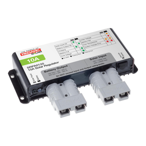
6.1 Power up
When connecting a battery, some or all (depending on the battery condition) of the
“BATTERY CONDITION” LED’s should light up.
The “LOAD DISCONNECT” LED might also light up, but will switch off after a few seconds if
no abnormal condition is present (See section 6.3).
6.2 Battery Charge
When the solar panel is charging the battery by more than 200mA, the green “SOLAR
CHARGE” LED will light up.
The “BATTERY CONDITION” LED’s give an indication of the current battery voltage as
follows:
LED’s On Battery Voltage
Green, Yellow and Red Greater than 12V
Yellow, Red Between 11.4V and 12V
Red Below 11.4V
6.3 Load
The load output provides a connection to drive a load of up to 10A at the current battery
voltage. The red “LOAD DISCONNECT” LED will light up and the load automatically
disconnect in the following scenarios:
6.3.1 Undervoltage Protection
When the battery voltage drops below 11.2V the load is disconnected to prevent damage
to the battery. As soon as the battery voltage recovers above 11.6V, the load will be
automatically reconnected and the LED will go off.
6.3.2 Overcurrent Protection
When the load terminals are short circuited or the connected load draws in excess of 10A,
the load will be disconnected. The load will be reconnected and the LED will go off in a
few seconds after the short circuit is removed or the load current falls below 10A.
If a higher load current is required, the load can be connected directly to the battery.
All protection will be bypassed in this case.
-------------------------------------------------------------------------------------------------------------------------
Rev A 2019/09/16 www.nemtek.com • nemtek@nemtek.com • Manufactured in South Africa
Operation
1. Introduction
The NEMTEK 140W Solar Regulator is designed to efficiently convert the output from a solar panel
to a level suitable for charging a 12V lead-acid battery, while Mean Power Point (MPP) technology
ensures that the maximum available power is harvested from the solar panel. The regulator
provides an output to drive a 12V load with a current consumption of up to 10A, as well as a load
disconnect function to protect the system and battery against under-voltage and over-current. Five
LED’s indicate the charging state, battery condition and load state.
2. Disclaimer & Guarantee
The 140W Solar Regulator, manufactured by NEMTEK, is guaranteed for a period of two years from
date of sale against defects due to faulty workmanship or material. NEMTEK will, at its discretion,
either repair or replace a product that proves to be defective. NEMTEK guarantees that the product,
when properly installed and used in line with the specification as determined by NEMTEK from time
to time, will execute its function. NEMTEK does not guarantee that the operation of the product will
be uninterrupted and totally error free. Faulty units must be returned to one of the NEMTEK Group
outlets. The buyer shall pay all shipping and other charges for the return of the product to NEMTEK
or NEMTEK Security Warehouse.
The guarantee does not apply to defects resulting from acts of God, modifications made by the
buyer or any third party, misuse, neglect, abuse, accident or mishandling. Product specifications
may be altered without prior notification.
3. Technical Specifications
Parameter Value
Power Handling Capability 140W
Efficiency @ 140W >90%
Maximum Solar Panel Input Voltage 24VDC
Solar Panel Input Range 20W – 200W
Battery Charge Voltage 14.3VDC
Suitable Lead Acid Battery Types Flooded, AGM, Gel
Recommended Battery Capacity (Solar Panel < 90W) >40Ah
Recommended Battery Capacity (Solar Panel > 90W) >90Ah
Maximum Flat Battery (11 VDC) Charge Current 11A**
Maximum Load Supply Current 10A**
Load Disconnect Voltage ~11.2VDC
Quiescent Current 60mA
Operating Temperature -20 – 55°C
Terminal Size 6mm
2
/ 12AWG
Mounting Hole Size 5mm
*Where applicable, all specifications are quoted at a temperature of 25°C
**Over-current protected
4. Warnings
1. This system may pose a fire hazard if not properly installed.
2. Always take care not to create a short circuit between opposite polarities.
3. This solar regulator employs positive switching. Never connect the positive outputs to a
common point.
4. It is highly recommended to install a 20A fuse in line with the positive polarity cable from the
regulator to the battery.
Introduction, Disclaimer, Guarantee
and Technical Specifications
5. Do not attempt to charge any battery other than a 12V lead-acid battery with a capacity that
is matched to the solar panel and load.
6. Always ensure sufficient ventilation for the regulator and battery. The regulator should always
be mounted on a vertical surface to ensure proper heat dissipation of the metal back plate.
7. Ensure all terminal screws are tightened firmly.
8. Keep the unit away from excessive moisture.
5. Installation
Refer to following steps in conjunction with the image when installing the solar regulator:
1. The unit should be mounted against a flat, vertical surface, by using the 5mm screw holes on
the sides. The unit must be installed in an environment with sufficient ventilation to ensure
operation within the temperature specifications as per section 2. Do not mount the unit on a
horizontal surface as this might cause overheating under heavy loads.
2. Connect the battery cables first to the regulator and then to the battery, ensuring the
correct polarity. It is strongly advised to install a 20A fuse, in-line with the positive cable from
the regulator to the battery. Care must be taken to use cables that can handle the maximum
regulator current. For maximum efficiency, 6mm2 should be used. Only connect the regulator
to a battery with a capacity suitable for the solar panel used.
3. Connect the solar panel cables, ensuring the correct polarity.
4. Make sure the load is switched off before connecting it to the regulator, ensuring correct
polarity.
5. To disconnect the regulator, follow the installation steps in reverse order.
6. Ensure all cables are kept as short as possible to maximise efficiency.
Warnings and Installation
Other manuals for SOL-REG140

1

Other Nemtek Controllers manuals

Nemtek FG7C User guide

Nemtek

Nemtek FG7C User guide

Nemtek SOL-REG140 User manual

Nemtek

Nemtek SOL-REG140 User manual

Nemtek FG7B User guide

Nemtek

Nemtek FG7B User guide

Popular Controllers manuals by other brands

Mitsubishi Electric MELSEC iQ-F FX5 user manual

Mitsubishi Electric

Mitsubishi Electric MELSEC iQ-F FX5 user manual

Maxcess MAGPOWR HEB250 Installation, operation and maintenance

Maxcess

Maxcess MAGPOWR HEB250 Installation, operation and maintenance

Maxcess MAGPOWR Spyder-Plus-S1 instruction manual

Maxcess

Maxcess MAGPOWR Spyder-Plus-S1 instruction manual

Preferred Instruments PCC-IV instruction manual

Preferred Instruments

Preferred Instruments PCC-IV instruction manual

Omega Engineering Dual Relay Option Board DPF700 user guide

Omega Engineering

Omega Engineering Dual Relay Option Board DPF700 user guide

Orton autofire express Instruction guide

Orton

Orton autofire express Instruction guide

HELVAR 478 installation guide

HELVAR

HELVAR 478 installation guide

MEDAP FINA RV O2/AIR operating instructions

MEDAP

MEDAP FINA RV O2/AIR operating instructions

Artecta ECOdrive DC15W Product sheet

Artecta

Artecta ECOdrive DC15W Product sheet

Texas Instruments TMDSHVMTRPFCKIT quick start guide

Texas Instruments

Texas Instruments TMDSHVMTRPFCKIT quick start guide

Dometic GP-PWM-10-FM user manual

Dometic

Dometic GP-PWM-10-FM user manual

Bartec Ex p Control Unit APEX manual

Bartec

Bartec Ex p Control Unit APEX manual

Transmitter Solutions RADIOBAND V3 Programming & installation manual

Transmitter Solutions

Transmitter Solutions RADIOBAND V3 Programming & installation manual

Philips dynalite DMRC210-RJ-DA installation instructions

Philips

Philips dynalite DMRC210-RJ-DA installation instructions

ADLINK Technology AMP-304C user manual

ADLINK Technology

ADLINK Technology AMP-304C user manual

PowerBox DPC-4000 Installation and operation instructions

PowerBox

PowerBox DPC-4000 Installation and operation instructions

Vacon 100X series Installation, Technical and Maintenance  Manual

Vacon

Vacon 100X series Installation, Technical and Maintenance Manual

LEGRAND Arteor 5 742 07 quick start guide

LEGRAND

LEGRAND Arteor 5 742 07 quick start guide

manuals.online logo
manuals.online logoBrands
  • About & Mission
  • Contact us
  • Privacy Policy
  • Terms and Conditions

Copyright 2025 Manuals.Online. All Rights Reserved.