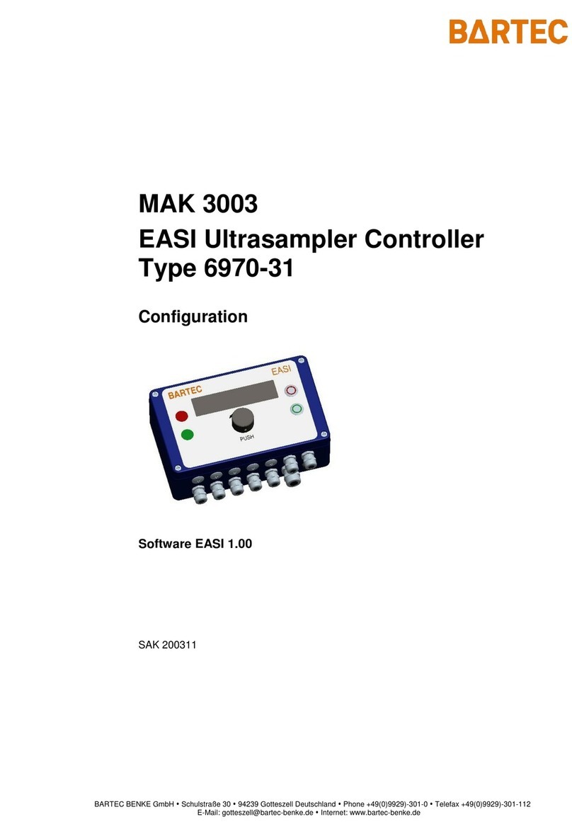
Bartec Ex p Control Unit APEX User manual

Manual Ex p Control Unit APEX
Set SIEMENS

BARTEC GmbH
Max-Eyth-Straße 16
97980 Bad Mergentheim
GERMANY
Phone: +49 7931 597-0
Fax: +49 7931 597-480
Internet: www.bartec.de
Operating Instructions
Safety Manual
SIEMENS Version
ATEX / IECEx Zone 1
Ex px Purge Unit
Type 05-0089-0076
Consisting of:
Ex px Control Unit APEX, type 07-37A2-3211/2726
Ex e Control Station, type 07-3103-2512/0639
Ex p Purge Unit
Type 05-0089-0077
Consisting of:
Ex px Control Unit APEX, type 07-37A2-3211/2726
Ex e Control Station, type 07-3103-2512/0639
p-Operator Panel, type 17-51P5-1111
Document number: 01-37A2-7D0004
Revision: 0
Order number: 449903

Page 2 of 80 01-37A2-7D0004_SIEMENS_Manual_Exp-Control-Unit_20220216_0_en.docx Rev. 0
Disclaimer: We reserve the right to make technical changes. Changes, errors and printing errors do not justify claims for damages.

Ex p Control Unit
SIEMENS Set
Table of contents
Rev. 0 01-37A2-7D0004_SIEMENS_Manual_Exp-Control-Unit_20220216_0_en.docx Page 3 of 80
Disclaimer: We reserve the right to make technical changes. Changes, errors and printing errors do not justify claims for damages.
0Table of contents
0Table of contents........................................................................................................ 3
1About these operating instructions ............................................................................. 7
Highlighting in the document ......................................................................................... 8
Warnings ........................................................................................................................ 8
Symbols and icons ......................................................................................................... 9
Technical changes.......................................................................................................... 9
Languages...................................................................................................................... 9
2Safety ...................................................................................................................... 10
Intended use ................................................................................................................ 10
Exclusive purpose ........................................................................................................ 10
Improper use................................................................................................................ 10
Qualification of staff .................................................................................................... 10
Warranty ...................................................................................................................... 11
Safety instructions....................................................................................................... 12
General ........................................................................................................................ 12
Safety instructions for operation.................................................................................. 12
Avoidance of damage to property ................................................................................. 13
Short circuit due to improper connection ..................................................................... 13
Triggering the safety function....................................................................................... 13
EMC-compliant connection.......................................................................................... 13
Storage at an excessively high temperature ................................................................. 13
Aggressive cleaning agents .......................................................................................... 14
Danger to health due to improper disposal................................................................... 14
Obligations of the owner............................................................................................... 14
Instructions for use ...................................................................................................... 14
Marking and test certificate ......................................................................................... 15
Ex p control unit APEX, type 07-37A2-3211/2726 ......................................................... 15
Ex e control station, type 07-3107-2512/0639.............................................................. 15
Standards complied with ............................................................................................. 15
Ex p control unit APEX, type 07-37A2-3211/2726 ......................................................... 15
Ex e control station, type 07-3103-2512/0639.............................................................. 16
SIL qualification / Safety according to IEC 61508 ......................................................... 17
SIL qualification ........................................................................................................... 17
Safety function............................................................................................................. 17
Safety parameters........................................................................................................ 18
Reaction time............................................................................................................... 18
Residual risk ................................................................................................................ 18

Table of contents
Ex p Control Unit
SIEMENS Set
Page 4 of 80 01-37A2-7D0004_SIEMENS_Manual_Exp-Control-Unit_20220216_0_en.docx Rev. 0
Disclaimer: We reserve the right to make technical changes. Changes, errors and printing errors do not justify claims for damages.
3Product description.................................................................................................. 19
General information ..................................................................................................... 19
Ex p control unit APEX, type 07-37A2-3211/2726 ......................................................... 19
Variant APEX, type 07-37A2-3211/2726........................................................................ 20
Ex e control station, type 07-3103-2512/0639.............................................................. 21
Variant Ex control station, type 07-3103-2512/0639..................................................... 21
Accessories.................................................................................................................. 22
p-operator panel .......................................................................................................... 22
Programming enable .................................................................................................... 22
Programming cable ...................................................................................................... 22
4Transport and storage .............................................................................................. 23
Scope of delivery.......................................................................................................... 23
Packaging..................................................................................................................... 23
Transport ..................................................................................................................... 24
Storage ........................................................................................................................ 24
Disposal ....................................................................................................................... 24
5Installation............................................................................................................... 25
Installation of the Ex p control unit, type 07-37A2-3211/2726...................................... 25
Installation of the Ex e control station, type 07-3103-2512/0639 ................................. 25
Installation of the purge gas supply.............................................................................. 26
Pneumatic connections................................................................................................ 27
Pneumatic overview ..................................................................................................... 28
Typical installation....................................................................................................... 29
6Electrical connections .............................................................................................. 30
General ........................................................................................................................ 31
Connection notes ......................................................................................................... 31
EMC-compliant connection.......................................................................................... 32
Pre-Fuse ...................................................................................................................... 33
Inductive loads............................................................................................................. 34
Electrical wiring Ex px Purge Unit ................................................................................. 35
Connection terminals “Ex e”......................................................................................... 36
Connection terminals “Ex i“.......................................................................................... 40
7Operation................................................................................................................. 46
WEB interface .............................................................................................................. 46
Setting the LAN connection.......................................................................................... 46
Operating the WEB interface ........................................................................................ 48
Registering with the WEB interface .............................................................................. 48
Navigating the WEB interface....................................................................................... 48

Ex p Control Unit
SIEMENS Set
Table of contents
Rev. 0 01-37A2-7D0004_SIEMENS_Manual_Exp-Control-Unit_20220216_0_en.docx Page 5 of 80
Disclaimer: We reserve the right to make technical changes. Changes, errors and printing errors do not justify claims for damages.
Entering parameters .................................................................................................... 49
LED indicators.............................................................................................................. 49
WEB interface menu structure ..................................................................................... 50
“Display“ menu ............................................................................................................ 51
“Passwort” menu ......................................................................................................... 51
“Network“ menu........................................................................................................... 51
Requesting “system status”......................................................................................... 52
Requesting “purge status“ ........................................................................................... 53
Reading out data container .......................................................................................... 54
8Commissioning......................................................................................................... 55
General information ..................................................................................................... 55
Pre Configuration Ex p control unit “SIEMENS Set”...................................................... 56
Purge phase ................................................................................................................. 56
Dilution phase .............................................................................................................. 56
Configuration of system accessories............................................................................ 57
“Temperature sensors“ setting .................................................................................... 57
“K2 / K3 / K4“ relay setting........................................................................................... 59
“OS 1 / OS 2“ sensor input setting ................................................................................ 60
Start up Ex p System.................................................................................................... 62
9Function check and sequence................................................................................... 63
Safety during operation................................................................................................ 63
Function flow diagram of the Ex p control unit ............................................................. 63
Flow diagram of the Ex p control unit ........................................................................... 63
10 Maintenance and care .............................................................................................. 64
Types of purge gas........................................................................................................ 64
Maintenance work........................................................................................................ 64
Maintenance intervals.................................................................................................. 64
Visual inspection.......................................................................................................... 65
Cleaning ....................................................................................................................... 65
Regular maintenance ................................................................................................... 65
Repairs......................................................................................................................... 65
Faults and troubleshooting .......................................................................................... 66
Faults........................................................................................................................... 66
Error messages ............................................................................................................ 68
11 Technical data.......................................................................................................... 71
Ex p Control Unit APEX ................................................................................................. 71
Ex e control station ...................................................................................................... 72

Table of contents
Ex p Control Unit
SIEMENS Set
Page 6 of 80 01-37A2-7D0004_SIEMENS_Manual_Exp-Control-Unit_20220216_0_en.docx Rev. 0
Disclaimer: We reserve the right to make technical changes. Changes, errors and printing errors do not justify claims for damages.
12 Order numbers ......................................................................................................... 73
Ex px purge unit, Version SIEMENS .............................................................................. 73
Ex p control unit APEX .................................................................................................. 73
Ex e control station ...................................................................................................... 73
Valve fuse..................................................................................................................... 73
Operator panel ............................................................................................................. 73
Optional cradle relay .................................................................................................... 73
Accessories.................................................................................................................. 73
13 Appendix.................................................................................................................. 74
Flow chart .................................................................................................................... 74
Software packages used .............................................................................................. 74
Dimensions .................................................................................................................. 75
Dimensions Ex p control unit APEX, type 07-37A2-3211/2726 ...................................... 75
Drilling pattern APEX, type 07-37A2-3211/2726 ........................................................... 75
Dimensions Ex e control station, type 07-3103-2512/0639........................................... 76
Drilling pattern Ex e control station, type 07-3103-2512/0639 ..................................... 76
14 Declaration of conformity ......................................................................................... 77
Ex p control unit APEX, type 07-37A2-3211/2726 ......................................................... 77
Ex e control station, type 07-3103-2512/0639.............................................................. 78
15 Note......................................................................................................................... 79

Ex p Control Unit
SIEMENS Set
About these operating instructions
Rev. 0 01-37A2-7D0004_SIEMENS_Manual_Exp-Control-Unit_20220216_0_en.docx Page 7 of 80
Disclaimer: We reserve the right to make technical changes. Changes, errors and printing errors do not justify claims for damages.
1About these operating instructions
Please read carefully before putting the device into operation.
Please observe the corresponding user manual.
This manual contains the information required for using the control unit in
accordance with its intended purpose. It is addressed to technically qualified
personnel.
Familiarity with and the technically perfect implementation of the safety
instructions and warnings described in this manual are preconditions for safe
installation and commissioning. The safety notes and warnings in these
operating instructions are given in a general manner and only qualified
personnel will have the necessary know how to interpret and implement them
correctly in specific individual cases.
These operating instructions are an integral part of the scope of delivery even
if, for logistical reasons, they can be ordered and delivered separately.
Should you require further information, please request the required
information from your local or responsible BARTEC branch. Read the
operating instructions and in particular the safety instructions carefully
before using the device.
Keep the operating instructions during the entire service life of the
device.
Make the brief instructions accessible to all persons entrusted with
handling the device.

About these operating instructions
Ex p Control Unit
SIEMENS Set
Page 8 of 80 01-37A2-7D0004_SIEMENS_Manual_Exp-Control-Unit_20220216_0_en.docx Rev. 0
Disclaimer: We reserve the right to make technical changes. Changes, errors and printing errors do not justify claims for damages.
Highlighting in the document
Warnings
Warnings are used in this user manual to warn of property damage and personal
injury.
Always read and follow these warnings.
Warnings are specially highlighted in this user manual and identified by symbols:
DANGER
DANGER indicates a hazardous situation which, if safety measures are not
observed, may result in death or serious injuries with permanent damage.
WARNING
WARNING indicates a hazardous situation which, if safety measures are not
observed, may result in serious injuries without permanent damage.
CAUTION
CAUTION indicates a hazardous situation which, if safety measures are not
observed, can result in minor injuries.
ATTENTION
ATTENTION indicates a hazardous situation which, if the safety measures
are not observed, may result in damage to property.
Explanation of the structure of a warning notice
WARNING WORD
Identifies the source of danger, cause of danger or type of danger
Consequence of non-compliance with the described safety measure.
Safety measure
Example of a warning notice
DANGER
Operation of the control unit in the case of damage!
Death or serious injury.
Put the control unit out of operation and secure it against restart.

Ex p Control Unit
SIEMENS Set
About these operating instructions
Rev. 0 01-37A2-7D0004_SIEMENS_Manual_Exp-Control-Unit_20220216_0_en.docx Page 9 of 80
Disclaimer: We reserve the right to make technical changes. Changes, errors and printing errors do not justify claims for damages.
Symbols and icons
Symbol
Explanation
Important notices and information for the effective, efficient and
environmentally friendly use of the product.
Ex application; this symbol indicates special information for Ex
applications
Safety function, this symbolism indicates special notes for safe
functions according to IEC 61508.
Technical changes
The current versions of the datasheets, operating instructions, certificates and
EC declarations of conformity as well as information on new accessories can be
downloaded from www.bartec.de under “Products” in the product area “Control
and Connection Equipment”, or requested directly from BARTEC GmbH.
Disclaimer: We reserve the right to make technical changes. Changes, errors and
printing errors do not justify claims for damages.
Languages
The original user manual is written in German. All other available languages are
translations of the original user manual.
The user manual is available in German and English. If further languages are
required, these must be requested from BARTEC or stated when placing the
order.

Safety
Ex p Control Unit
SIEMENS Set
Page 10 of 80 01-37A2-7D0004_SIEMENS_Manual_Exp-Control-Unit_20220216_0_en.docx Rev. 0
Disclaimer: We reserve the right to make technical changes. Changes, errors and printing errors do not justify claims for damages.
2Safety
Intended use
Exclusive purpose
The Ex p control unit APEX serves exclusively as a controlling and monitoring
device for pressurized enclosures and is intended for use in explosion group II,
category 2G (EPL Gb) and temperature class T4.
Furthermore, the safety function of the Ex p control unit APEX satisfies the
requirements on SIL 2 according to IEC 61508 and performance level “d“
according to EN ISO 13849-1. The permissible operating data of the device used
must be observed.
Improper use
Any other use is not in accordance with the intended purpose and may lead to
damage and accidents. The manufacturer will not be liable for any use beyond
that of its intended purpose.
Qualification of staff
Target group
Skills
Design /
engineering
Technical training
Knowledge and experience to identify and avoid
hazards that may be caused by electricity
Understanding of the overall system
Configuration / programming
Special induction for the Ex area
Electrician / installer
Technical training
Knowledge and experience to identify and avoid
hazards that may be caused by electricity
Understanding of the overall system
Special induction for the Ex area
Operator
Induction in operation by the owner
Special induction for the Ex area
Storage and transport
companies
Loading and transport activities
Professional storage

Ex p Control Unit
SIEMENS Set
Safety
Rev. 0 01-37A2-7D0004_SIEMENS_Manual_Exp-Control-Unit_20220216_0_en.docx Page 11 of 80
Disclaimer: We reserve the right to make technical changes. Changes, errors and printing errors do not justify claims for damages.
Warranty
WARNING
UNAUTHORISED MODIFICATIONS AND/OR ALTERATIONS TO THE CONTROL
SYSTEM.
Explosion protection as well as design and manufacture in line with strain
and safety requirements are no longer guaranteed.
Before making any modifications or alterations, contact the
manufacturer to obtain written approval.
Use only original spare parts and original wearing parts.
Assumption of warranty
The manufacturer assumes the complete warranty only and
exclusively for the spare parts ordered from the manufacturer.
As a basic rule, our “General Terms, Conditions of Sale and Delivery” apply. They
are available to the managing operator on conclusion of contract at the latest.
Warranty and liability claims for personal injury and damage to property are
excluded if they are due to one or several of the following reasons:
Improper use of the Ex p control unit.
Incorrect installation, commissioning, operation and maintenance of the
Ex p control unit.
Non-compliance with the instructions in the manual with respect to
transport, storage, assembly, commissioning, operation and maintenance.
Unauthorized structural changes to the Ex p control unit.
Inadequate monitoring of parts that are subject to wear.
Improperly performed repairs.
Disasters caused by foreign bodies and force majeure.
We guarantee the Ex p control unit and its accessories for a period of one year
starting on the date of delivery from the Bad Mergentheim plant. This warranty
covers all parts of the delivery and is restricted to the replacement free of charge
or the repair of the defective parts in our Bad Mergentheim plant. Any packaging
delivered here should be kept where possible. If necessary, the goods should be
sent to us after written agreement. There is no entitlement to rectification at the
site of installation.

Safety
Ex p Control Unit
SIEMENS Set
Page 12 of 80 01-37A2-7D0004_SIEMENS_Manual_Exp-Control-Unit_20220216_0_en.docx Rev. 0
Disclaimer: We reserve the right to make technical changes. Changes, errors and printing errors do not justify claims for damages.
Safety instructions
General
Do not dry wipe or clean devices in hazardous areas!
Do not open devices in hazardous areas.
The general statutory regulations or guidelines relating to safety at work,
accident prevention and environmental protection legislation must be
observed, e.g. the German Industrial Health and Safety Ordinance
(BetrSichV) or the applicable national ordinances.
Wear suitable clothing and footwear in view of the risk of dangerous
electrostatic charges.
Avoid exposure to heat outside the specified temperature range (see
Chapter “General technical data”).
Avoid exposure to moisture.
Safety instructions for operation
Commissioning
Before commissioning, check that all components and documents are
available.
Inspection
Under EN/IEC 60079-17, the owner of electrical systems in hazardous
areas is obliged to have them checked by a qualified electrician to ensure
that they are in a proper condition.
Maintenance
For electrical systems, the relevant installation and operating regulations
must be observed (e.g. Directive 99/92/EC, Directive 2014/34/EUEC,
BetrSichV or the nationally applicable ordinances EN/IEC 60079-14 and
the DIN VDE 0100 series)!
Please observe the national waste disposal regulations for disposal.
Servicing
Regular servicing is not necessary if the device is operated correctly in
accordance with the installation instructions and ambient conditions.
BARTEC recommends annual servicing and inspection.
See Chapter “Maintenance and care”.

Ex p Control Unit
SIEMENS Set
Safety
Rev. 0 01-37A2-7D0004_SIEMENS_Manual_Exp-Control-Unit_20220216_0_en.docx Page 13 of 80
Disclaimer: We reserve the right to make technical changes. Changes, errors and printing errors do not justify claims for damages.
Repairs
Repairs on explosion-protected equipment may be done only by authorized
persons working in accordance with the latest development in technology
and using original spare parts. The applicable provisions must be
observed.
Repairs must be carried out in accordance with EN / IEC 60079-19.
For SIL-qualified devices, only a corresponding electronics module with
SIL qualification may be used.
All application settings must be re-entered. Therefore, you must conduct a
restart after a repair. If you have saved the data of parameter assignment
the first time you commissioned the Ex p control unit, you can transfer
them back to the replacement control unit. Detailed information on the
replacement of spare parts can be found in these operating instructions.
After restart or transfer of the parameter assignment data, you must verify
the parameters. Only then will the device be ready for operation again.
For Ex applications, only one device and one electronic module may be
used with corresponding Ex approval. Order the spare parts from your local
representative. The serial number can be found on the type plate of the
device, inside the enclosure.
Avoidance of damage to property
Short circuit due to improper connection
An incorrect connection of the power supply will destroy the electronics and void
the warranty.
Triggering the safety function
Switching on again too quickly after switching off can cause internal voltage
peaks in the power supply unit and thus trigger a safety function. After switching
off the voltage path, wait at least 30 seconds before switching on again.
EMC-compliant connection
For the safe function of the Ex p control unit it is important to carry out the wiring
in accordance with EMC. This includes observing the chapter Electrical
connections with regard to EMC-compliant wiring and inductive loads.
Storage at an excessively high temperature
Store the Ex p control unit at the intended storage temperature since otherwise
damage to the electronics or seals may occur. Ensure adequate air conditioning
at high storage temperatures.

Safety
Ex p Control Unit
SIEMENS Set
Page 14 of 80 01-37A2-7D0004_SIEMENS_Manual_Exp-Control-Unit_20220216_0_en.docx Rev. 0
Disclaimer: We reserve the right to make technical changes. Changes, errors and printing errors do not justify claims for damages.
Aggressive cleaning agents
When selecting the correct cleaning agent, it is essential that it is suitable for
use since otherwise damage may occur to seals and connections. Combustible
products are generally not permitted.
Danger to health due to improper disposal
According to the European WEEE Directive, electrical and electronic equipment
may not be disposed of with household waste. Their components must be sent
separately for recycling or disposal because toxic and hazardous components
can cause long-term damage to health and the environment if not disposed of
properly.
As consumers, you are obliged under the Electrical and Electronic Equipment Act
(ElektroG) to return electrical and electronic equipment at the end of its
serviceable life free of charge to the manufacturer, the point of sale or to public
collection points set up for this purpose. Details of this are regulated by the
respective national law. The symbol on the product, the operating instructions
or/and the packaging refers to these regulations. With this type of material
separation, recycling and disposal of old devices, you make an important
contribution to the protection of our environment.
Obligations of the owner
The owner undertakes to restrict permission to work with and on the APEX
control unit to people who:
are familiar with the basic regulations on safety and accident prevention
and have been instructed in the use of the APEX control unit;
have read and understood the documentation, the chapter on safety and
the warnings.
The owner must check that the safety regulations and accident prevention
rules valid for the respective application are observed.
Instructions for use
The overvoltage category II of the non-intrinsically safe circuits according
to IEC 60664-1 must be observed.
The warning “WARNING – DO NOT OPEN UNDER VOLTAGE” must be part of
the external marking of the entire electrical device or the enclosure must
have a locking system to prevent the fuses from being energized during
replacement.

Ex p Control Unit
SIEMENS Set
Safety
Rev. 0 01-37A2-7D0004_SIEMENS_Manual_Exp-Control-Unit_20220216_0_en.docx Page 15 of 80
Disclaimer: We reserve the right to make technical changes. Changes, errors and printing errors do not justify claims for damages.
Marking and test certificate
Ex p control unit APEX, type 07-37A2-3211/2726
ATEX (Europe)
Marking
II 2(1)G Ex eb mb ib [ib pxb] [ia Ga] IIC T4 Gb
EU-Type Examination Certificate
BVS 19 ATEX E 015 X
IECEx (International)
Marking
Ex eb mb ib [ib pxb] [ia Ga] IIC T4 Gb
IECEx Certificate of Conformity
IECEx BVS 19.0038X
Ex e control station, type 07-3107-2512/0639
ATEX (Europe)
Marking
II 2G Ex db eb ib IIC T4 Gb
EU-Type Examination Certificate
IBExU 12 ATEX 1099 X
IECEx (International)
Marking
Ex db eb ib IIC T4 Gb
IECEx Certificate of Conformity
IECEx IBE 12.0031 X
Standards complied with
Ex p control unit APEX, type 07-37A2-3211/2726
Standard
Designation
EN IEC 60079-0:2018/AC:2020
IEC 60079-0:2011 Edition: 6.0
Explosive atmospheres –Part 0: General
requirements
EN 60079-2:2014
IEC 60079-2:2007 Edition: 5.0
Explosive atmospheres - Part 2: Equipment
protection by pressurized enclosure “p”
EN 60079-7:2015/A1:2018
IEC 60079-7:2006 Edition: 4.0
Explosive atmospheres - Part 7: Equipment
protection by increased safety “e”
EN 60079-11:2012
IEC 60079-11:2011 Edition: 6.0
Explosive atmospheres - Part 11: Equipment
protection by intrinsic safety “i”
EN 60079-18:2015/A1:2017
IEC 60079-18:2014 Edition: 4.0
Explosive atmospheres - Part 18: Equipment
protection by cast encapsulation “m”
EN 60079-31:2014
IEC 60079-31:2013 Edition: 2.0
Explosive atmospheres - Part 31:
Equipment dust ignition protection by enclosure “t”
EN 61010-1:2010
IEC 61010-1:2010 Edition 3.0
Safety requirements for electrical equipment for
measurement, control and laboratory use –Part 1:
General requirements
EN 61000-6-4:2007 + A1:2011
IEC 61000-6-4:2018 Edition 3.0
Electromagnetic compatibility (EMC) –
Part 6-4: Generic standards –Emission standard
for industrial environments

Safety
Ex p Control Unit
SIEMENS Set
Page 16 of 80 01-37A2-7D0004_SIEMENS_Manual_Exp-Control-Unit_20220216_0_en.docx Rev. 0
Disclaimer: We reserve the right to make technical changes. Changes, errors and printing errors do not justify claims for damages.
Standard
Designation
EN 61000-3-2:2014
IEC 61000-3-2:2018 Edition 5.0
Electromagnetic compatibility (EMC) –
Part 3-2: Limits –Limits for harmonic current
emissions (equipment input current <= 16 A per
phase)
EN 61000-3-3:2013
EN 61000-3-3:2013 +
AMD1:2017 Edition 3.1
Electromagnetic compatibility (EMC) –
Part 3-3: Limits –Limitations of voltage changes,
voltage fluctuations and flicker in public low-
voltage supply systems for equipment with rated
current <= 16 A per phase, and not subject to
conditional connection
EN 61326-1:2013
IEC 61326-1:2012
Electrical equipment for measurement, control
and laboratory use –EMC requirements –Part 1:
General requirements
EN ISO 13849-1:2015
Safety of machinery - Safety-related parts of
control systems - Part 1: General principles for
design
EN ISO 13849-2:2012
Safety of machinery - Safety-related parts of
control systems - Part 2: Validation
DIN EN 62061:2016
IEC 62061:2015
Safety of machinery - Functional safety of safety-
related of electrical, electronic and programmable
electronic control systems
Ex e control station, type 07-3103-2512/0639
Standard
Designation
EN IEC 60079-0:2018/AC:2020
IEC 60079-0:2011 Edition: 6.0
Explosive atmospheres –Part 0: General
requirements
EN 60079-1:2014
IEC 60079-1:2014 Edition: 7.0
Explosive atmospheres - Part 1: Equipment
protection by flameproof enclosures “d”
EN 60079-7:2015/A1:2018
IEC 60079-7:2006 Edition: 4.0
Explosive atmospheres - Part 7: Equipment
protection by increased safety “e”
EN 60079-11:2012
IEC 60079-11:2011 Edition: 6.0
Explosive atmospheres - Part 11: Equipment
protection by intrinsic safety “i”

Ex p Control Unit
SIEMENS Set
Safety
Rev. 0 01-37A2-7D0004_SIEMENS_Manual_Exp-Control-Unit_20220216_0_en.docx Page 17 of 80
Disclaimer: We reserve the right to make technical changes. Changes, errors and printing errors do not justify claims for damages.
SIL qualification / Safety according to IEC 61508
The SIL qualification is only valid for the version of type
07-37A2-***1/**** (APEX).
Important notes and information on the safe handling
of the product.
SIL qualification
During the development of the Ex p control unit, special attention is paid to the
avoidance of systematic errors and the detection and control of random errors.
The most important characteristics and requirements from the point of view of
functional safety according to IEC 61508 are as follows:
Internal monitoring of safety-relevant circuitry parts
In the event of an error, transition of the safety-relevant outputs to a
defined safe state
Determination of the failure probability of the defined safety function
Safe parameter assignment with non-safe operating environment
Re-test
The SIL qualification of components is documented in this manual. All safety-
relevant characteristic data required by the user and the planner for project
planning and operation of the safety-instrumented system are summarized in
this chapter. Further SIL-relevant information is integrated in this manual.
Safety function
The safety function of the Ex p control unit is the purge with a defined quantity of
purge gas, the safe monitoring of the internal overpressure of the protected
equipment and the release for operation. The safe state means that in the event
of a drop in pressure or malfunction, the Ex p control unit switches to the safe
state = deactivation of the protected equipment.
The “safe state” is triggered by:
Falling below the minimum pressures within the Ex p equipment
Illogical pressure values within the Ex p equipment
Failure of the supply voltage
If the Ex p control unit does not deactivate or does not change to the safe state
on request or in the case of an error, a hazardous failure exists.

Safety
Ex p Control Unit
SIEMENS Set
Page 18 of 80 01-37A2-7D0004_SIEMENS_Manual_Exp-Control-Unit_20220216_0_en.docx Rev. 0
Disclaimer: We reserve the right to make technical changes. Changes, errors and printing errors do not justify claims for damages.
Safety parameters
THE FOLLOWING SAFETY PARAMETERS ARE WITHOUT OPTIONAL
SENSORS.
The optional sensors must be considered to determine the total
failure rate!
The safety parameters may be derived from the
documentation on the optional sensors used.
Safety parameters according to IEC/EN 61508 / DIN EN ISO 13849-:
SIL = 2
Performance Level: = d
PFHsys = (PFH_S+_PFH_L+PFH_FE+PFH_C) = 1.70E-08
HFT = 1
SFFsys = 92.85 %
MTTFd = 76 Yr
DC = 88.78 %
Device type B (complex equipment)
Interval of retests = 1 year
Category 3
Reaction time
The reaction time of the Ex p control unit to safety-relevant functions without
specific user delay times is smaller than 2 seconds.
With the Ex p control unit it is possible to set a delay time for pressure
fluctuations below the minimum pressure.
This results in a delay time of
TReaction = TControl + TDelay
TReaction = Time required by the Ex p control unit APEX to react to a safety-
relevant function
TControl = Internal time required by the Ex p control unit to recognize the
safety-relevant triggering. < 2 seconds
TDelay = Adjustable delay time for safety-relevant triggering which is
added to the reaction time TControl.
Residual risk
Residual risks may arise from:
Errors in project planning
Errors in operating
Errors in wiring

Ex p Control Unit
SIEMENS Set
Product description
Rev. 0 01-37A2-7D0004_SIEMENS_Manual_Exp-Control-Unit_20220216_0_en.docx Page 19 of 80
Disclaimer: We reserve the right to make technical changes. Changes, errors and printing errors do not justify claims for damages.
3Product description
General information
The Ex p control set described here is intended for use in pressurized equipment
in the “containment system“ version.
The set described here is preset for the SIEMENS analyses of the 6 series and
can be used without further parameter settings.
Ex p control unit APEX, type 07-37A2-3211/2726
The APEXcontrol unit of type 07-37A2-3211/2726 is specially
designed for Ex p systems with the concept of a "containment
system with continuous operating flow".
For this purpose, the APEX control unit operates according to
the procedure described in EN 60079-2, chapter 13.3. In this
process, the Ex p control unit purges the protected volume and then safely
prevents the occurrence of a dangerous concentration of explosive gas mixtures
by means of a continuous operating flow.
Due to the higher pressure inside the protected volume compared to the
atmosphere, explosive gases cannot enter the pressurized enclosure from the
outside at any time.
After mounting the APEX control unit and connecting the purge gas connections
to the volume to be protected, and after connecting the mains voltage and purge
gas, the Ex p system starts automatically. The Ex p control with the APEX control
unit regulates the purge gas flow and the nominal enclosure pressure during the
pre-purge phase, as well as the nominal enclosure pressure and the operating
flow during the operating phase.
Table of contents
Other Bartec Controllers manuals