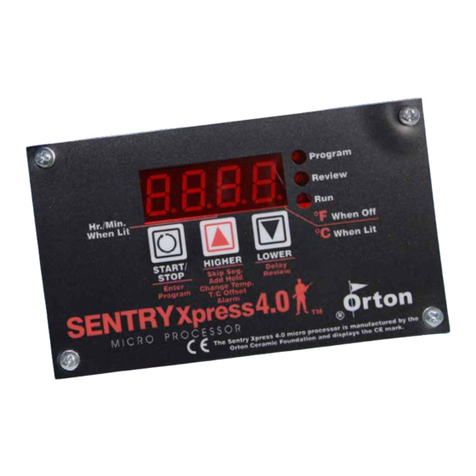
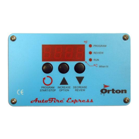
Orton autofire express Manual

rA1 = 0250
°F 1 = 0750
HLd1 = 00.00
rA2 = 0900
°F 2 = 1425
HLd2 = 00.30
rA3 = FULL
°F 3 = 1050
HLd3 = 00.00
rA4 = 0150
°F 4 = 0750
HLd4 = 00.00
rA5 = 0000
4. The display shows Strt after the final entry above.
5. Press (Program) button one last time to start the firing. Display will show -
On-
Heat Treating Program Example
Below is a typical 3 step firing schedule for Heat Treating Steel.
Step 1. Heat as fast as possible from starting temperature to 1800°F, Hold
at 1800°F for 20 minutes
Step 2. Cool as fast as possible from 1800°F to 400°F, with no hold time at
400°F
Step 3. Heat as fast as possible from 400°F to 500°F, Hold at 500°F for 5
hours, and then Shut-off
To program this schedule from IdLE mode;
1. Press (Program) button. The controller will display the last active
program that was used. PrO1 –PrO9
2. Press (Program) button again if you want to use the same program that
is shown or press (Increase) button to change to another program and
then press (Program) button again.
3. Program the steps below and press (Program) button after each segment.
rA1 = FULL
°F 1 = 1800
HLd1 = 00.20
rA2 = FULL
°F 2 = 0400
HLd2 = 00.00
rA3 = FULL
°F 3 = 0500
HLd3 = 05.00
rA4 = 0000
4. The display shows Strt after the final entry above.
5. Press (Program) button one last time to start the firing. Display will show -
On-
12
Autofire®Express
Ramp/Hold Controller
Instruction Guide
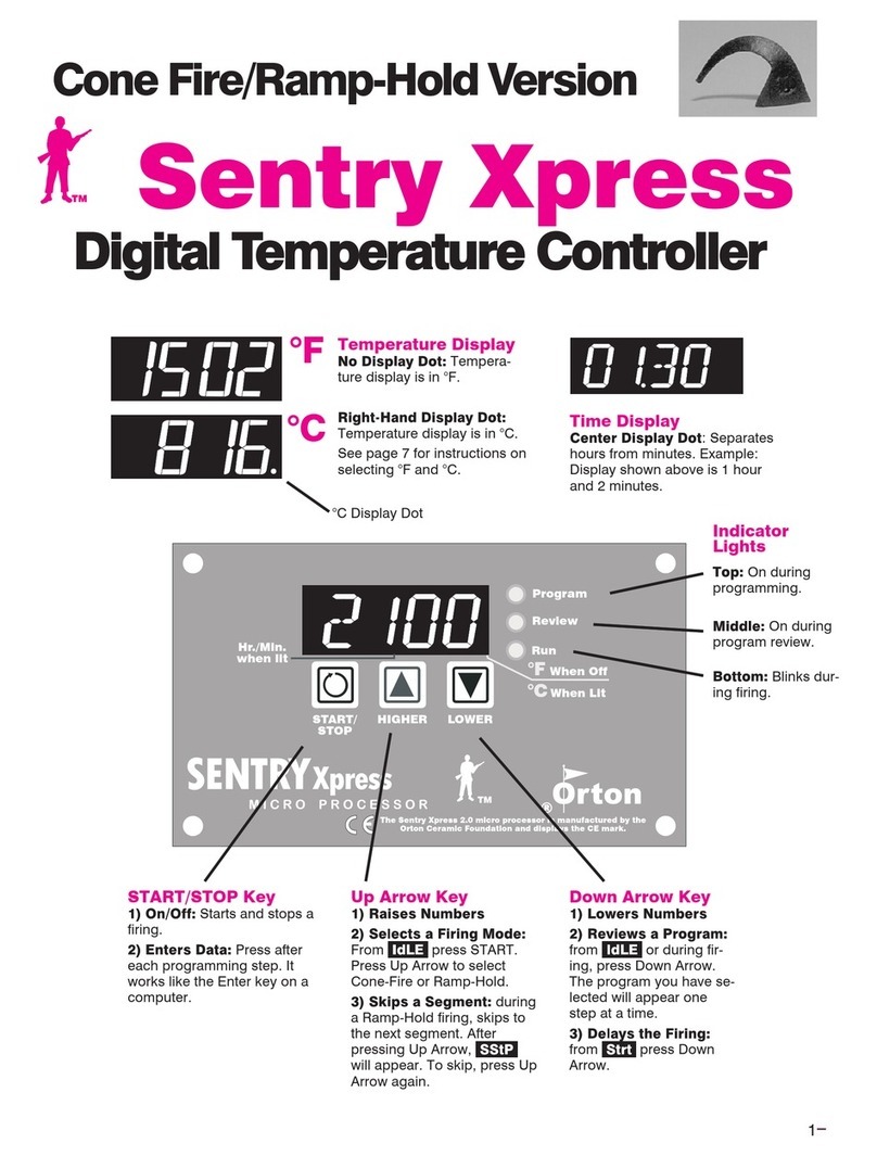
This button is for selecting a firing program and advancing
through the programming steps. After programming is
complete, use this button to Start and Stop the firing.
This button is used to change the firing program during
programming and to change the display values for specific
program settings. During a firing, use this button for special
firing options (including Skip Step).
This button is used to change the display values for specific
program settings. It is also used to activate the Program
Review feature.
When using the Increase and Decrease buttons to
change number settings, the values will change
more rapidly if the button is held in.
1

Status Indicator Lights
3 lights are located to the right of the display.
Θ Program lit during controller programming
Θ Review lit during Program Review.
Θ Run lit (blinks) during an active firing.
Audible Alarm
The controller is equipped with a small buzzer that will sound during button
presses and at the successful completion of a firing for 30 seconds. The
alarm will also sound to notify you of diagnostic alarms that may occur during
a firing. To silence an active buzzer, Press any button.
Temperature display preference
All temperature displays on the controller can be viewed as °F (Fahrenheit) or
°C (Celsius). The temperature display preference is set by positioning a small
circuit board jumper on the back side of the controller that is labeled C/F. The
C/F jumper has 2 pin positions, when installed on the 2 corresponding circuit
board pins the controller will display all temperatures as °F(Fahrenheit). When
no jumper is installed on the 2 circuit board pins the controller will display all
temperatures as °C (Celsius). To determine if your controller is set for °F or °C
without viewing the jumper position, the small decimal point light in the bottom
right-hand corner of the display panel indicates °F or °C. If this decimal point
light is lit, the controller is set for °C.
The C/F jumper position is shown on the wiring diagram included in
this manual.
Temperature Measurement
The controller monitors and controls temperature from a single Type K
thermocouple sensor. Thermocouple probes extend into the firing chamber
to measure the temperature. Use caution to avoid damage to the system
thermocouple. If the probe is damaged, the controller may not function
properly.
Temperature Control
The controller heats the firing chamber by turning relays on and off at the
appropriate rate to maintain the program schedule. It is normal to hear the clicking
noises associated with turning relays on and off throughout the firing.
Understanding Firing Programs
Orton controllers require 3 variables for each heating or cooling step of a
firing schedule. These variables are;
1. Heating or cooling rate (Speed)
2. Heating or cooling temperature
3. Hold time (Soak) at heating or cooling temperature.
2
Ceramic Glaze (Cone06) Firing Program Example
Below is a typical 4 step firing schedule for Ceramic Glaze Firing to Cone06.
Step 1. Heat from starting temperature to 1031°F at 360°F/Hour, with no
Hold time at 1031°F
Step 2. Heat from 1031°F to 1103°F at 180°F/Hour, with no Hold time at
1103°F
Step 3. Heat from 1103°F to 1675°F at 297°F/Hour, with no Hold time at
1675°F
Step 4. Heat from 1675°F to 1828°F at 108°F/Hour, with no Hold time at
1828°F, then Shut-off
To program this schedule from IdLE mode;
1. Press (Program) button. The controller will display the last active
program that was used. PrO1 –PrO9
2. Press (Program) button again if you want to use the same program that
is shown or press (Increase) button to change to another program and
then press (Program) button again.
3. Program the steps below and press (Program) button after each segment.
rA1 = 0360
°F 1 = 1031
HLd1 = 00.00
rA2 = 0180
°F 2 = 1103
HLd2 = 00.00
rA3 = 0297
°F 3 = 1675
HLd3 = 00.00
rA4 = 0108
°F 4 = 1828
HLd4 = 00.00
rA5 = 0000
4. The display shows Strt after the final entry above.
5. Press (Program) button one last time to start the firing. Display will show -
On-
Glass Fusing/Slumping Firing Program Example
Below is a typical 4 step firing schedule for Glass Slumping or Fusing.
Step 1. Heat from starting temperature to 750°F at 250°F/Hour, with no
Hold time at 750°F
Step 2. Heat from 750°F to 1425°F at 900°F/Hour, Hold at 1425°F for 30
minutes
Step 3. Cool as fast as possible from 1425°F to 1050°F, with no Hold time
at 1050°F
Step 4. Cool from 1050°F to 750°F at 150°F/Hour, and then Shut-off
To program this schedule from IdLE mode;
1. Press (Program) button. The controller will display the last active
program that was used. PrO1 –PrO9
2. Press (Program) button again if you want to use the same program that
is shown or press (Increase) button to change to another program and
then press (Program) button again.
3. Program the steps below and press (Program) button after each segment.
11

FE # - Fatal software Errors, FE Alarms indicate a hardware failure or
software problem with the controller. These alarms will disable the normal
controller operation and require corrective action. If a Fatal Error occurs during
an active firing, the firing is terminated. These alarms include;
FE 1 –Failed to read or write to memory device
FE 2 –Failed memory test during power on
FE 3 –Corrupt data found in memory
FE 4 –Errors detecting thermocouple input signal
FE 5 –Software Execution failed
Turn the controller off and back on, then press any button to try and clear the
alarm. If the alarm reoccurs immediately or frequently, the controller may
require service or replacement.
Firing Schedules/Programs
You can store/save up to 9 separate firing programs in the controller
memory. Each program can be up to 8 Steps long. During programming the
display prompts for the individual firing schedules are PrO followed by the
program number like PrO1, PrO2, PrO3, etc…
If your controller does not allow for 9 programs, it has been factory set by the
supplier for a limiting number of programs. This is often necessary for special
applications.
To select any of the available programs, first press the Program button when
the display shows IdLE. The last used program will be the first choice on the
controller display. If a different program is desired, press the Increase button
to select another program. Then press the Program button again when the
displays shows the program code you want.
Flow Diagram for Program Selection
10
A complete firing schedule can be multiple heating and/or cooling
steps. However, for many applications a single step is all that is
required. The maximum number of program steps is limited to 8.
Programming Heating and Cooling Rate
Each step of a firing program must have a programmed Rate of temperature
increase or decrease. This is the speed of the heat-up or cool-down. These
rate values are selected as Degrees per Hour. ‘Degrees per hour’ rate can be
determined by dividing the total amount of temperature change by the number
of hours required to achieve the temperature change. For Example, If you
want to heat the kiln to 900°F from room temperature (72°F) in 2 hours time.
The heating rate would be 414 Degrees/hour. [900-72 = 828, 828/2 = 414]
During programming the display prompts for all Rate settings are
rA followed by the step number like rA 1,rA 2,rA 3, etc…
The values available for setting Rate are 0 -1798°F/hour or 0-998°C/hour. If
it’s desired to heat or cool as fast as possible, an alternative setting is
available at the beginning or end of the temperature range. This setting
appears as FULL on the controller display.
Entering Zero for a heating or cooling rate
The controller determines where your firing program ends by the rA value. If
zero is set for any Rate, this tells the controller that there are no more steps to
your firing schedule. If additional steps had previously been saved in the
active program, all steps after the zero entry will be erased. This feature can
also be used to erase an entire firing program by setting the first rA 1 value to
zero.
Programming Heating or Cooling Temperatures
Each step of a firing program must have a programmed heating or cooling
temperature. The controller must have at least one heating step to accept the
firing program as valid (an invalid program results in a bAdP display alarm).
A heating step is simply any step with a temperature setting that is above the
current display temperature.
Cooling steps are automatically determined by the temperature value. If a
heating or cooling temperature value is programmed to a lower setting than
the previous heating or cooling temperature, it will be a cooling step.
During programming the display prompts for all Heating or Cooling
Temperature settings is °F (or °C) followed by the step number like
°F 1,°F 2, °F 3, etc…
The temperature range available for setting heating or cooling temperatures is
32-2400°F or 0-1316°C. If the controller does not allow you to program
temperatures up to 2400°F/1316°C, it has been factory set by the supplier to a
lower safety temperature. This is often necessary to limit the controller to the
maximum operating temperature of the system.
3

Programming Hold Time
Each step of a firing program can have an optional Hold time. Hold time is
the amount of time you want to stay at the previously determined heating or
cooling temperature. Hold time is also referred to as Soak or Dwell time.
Hold Time is entered in Hours & Minutes format. The middle decimal point
light on the controller display is used to separate Hours from Minutes. For
Example, A 1 hour hold time should be set like [01.00], while a 1 hour and
30 minute hold time would be [01.30]. If no hold time is desired, the setting
should be [00.00]
A special Hold time is available for indefinite Hold periods. If it is desired to
hold the program temperature until someone manual stops the firing or
manually advances the program, a hold time of [99.59] represents
indefinite Hold.
The value range available for setting Hold time is 00.00 to 99.58.
During a firing, the hold time begins as soon as the temperature reaches the
heating or cooling temperature. As the hold time progresses, the controller
display will count-down the remaining time until the hold time has expired.
During programming the display prompts for all Hold settings is HLd
followed by the step number like HLd1, HLd2, HLd3, etc…
Other Programming Notes
After a firing program is set in the controller, the values will not change or
be lost when the controller is turned off.
It is not possible to back-up in the programming mode. If a mistake is made
while programming a previous step, you must start over from the IdLE mode
to make corrections.
If no buttons are pressed for 1 full minute during programming, the controller
will automatically exit the program mode and return to the IdLE display.
During a firing, if the options menu is activated for programming, the controller
will return to the active display if no buttons are pressed for 1 full minute.
Delay Start Option
Prior to the active start of any firing, the controller display will show a Start
prompt of Strt. This appears after the firing program selection and
programming. If a delay start time is desired, press the Decrease/Review
button to activate a delay start prompt. The display will show dELA
alternating with the adjustable delay time in Hours & Minutes format. Use the
Increase/Decrease buttons to set the Delay time and then press the Program
button to return to the Strt prompt. When you are ready to begin the delay
period, press the Program button again.
Delay time counts-down on the controller display before the actual start of the
firing. When the delay time expires, the actual firing program begins
automatically. The Delay time has a setting range of 00.00 (no delay) to
99.59 (99 hours. 59Minutes)
4
the wiring for the thermocouple and the physical condition of the probe
inside the firing chamber.
FtL -This alarm indicates that the firing was taking too much time to complete
and the firing was terminated. The controller monitors the deviation from the
desired firing schedule as compared with the actual firing results. There are 2
conditions for the FTL alarm.
1. The heating or cooling rate is slower than 27°F (15°C) per Hour
2. The current program step has lasted 2 hours longer
than anticipated.
In most cases, the FTL alarm occurs during heating if the heating rate is set
to a fast speed that cannot be maintained by the kiln. If the heating rate is
within the systems capability, a component failure has probably occurred with
the heating elements or the heater relays.
During cool-down, a well insulated system will have cooling limitation and
rapid cooling rates may set off this alarm if the cooling speed cannot be
maintained. Increasing the final cool-down temperature or slowing the
programmed cooling rate can avoid this alarm.
tCL -This alarm indicates that the thermocouple signal is not responding to the
demand for more system power during heat-up. There are 3 conditions for the tCL
alarm.
1. The heating rate is slower than 9°F (5°C) per Hour
2. The actual kiln temperature is lagging behind the desired
setpoint temperature by more than 100ºF (56ºC).
3. The actual temperature is less than 500ºF (260ºC)
In all cases, the tCL alarm occurs during heating when little temperature rise
is detected. This can be the result of a component failure; most likely a failed
heating elements or a heater relay. Another possible problem is with the
thermocouple sensor signal; if the thermocouple probe is not properly
positioned in the firing chamber or if the wiring from the thermocouple has
short -circuited the controller will not detect actual temperature changes in
the firing chamber.
EtH -This alarm indicates that the Electronics temperature is too hot for
controller operation. The controller temperature must be below176ºF (80ºC) to
prevent damage to the electronic components. The ETH alarm cannot be cleared
unless the board temperature has cooled. If the ETH occurs frequently, check the
kiln for heat loss near the controller. Proper venting and heat-shielding should be
inspected.
HtdE -The High Temperature deviation alarm sounds an audible alarm and
terminates the firing if the actual kiln temperature is above the controller set-point
by 56ºC (100ºF). This alarm is active only when the actual kiln temperature is
above 500ºF (260ºC)
9

Status Display Codes
Below is a list of normal display codes which indicate the controller mode of
operation.
IdLE - This is ready mode; No firing in process. This message will alternate
with the temperature display and/or any alarm messages that may occur.
dELA - This is the delay start mode. This message will alternate with the
delay time count-down if programmed.
Strt - This is a final prompt before starting a new firing. The Delay start and
Thermocouple Offset features are accessed from this prompt.
-On- - This is a short (5 second) display that indicates a new firing has
been started.
StOP - This is an Abort message; the firing was stopped early. This
message will alternate with the temperature display and/or any alarm
messages that may occur.
CPLt - This is a firing complete message; the firing ended successfully.
This message will alternate with the temperature display and the total firing
time from start to finish.
x-4 - This is a short (5 second) display of the Model number which
appears every time the controller is turned on.
Alarm Display Codes
In addition to Power failure alarms, these messages may be displayed if the
controller detects a problem during the firing.
tC -This alarm indicates that the thermocouple sensor is no longer detected. The
controller can not operate without a thermocouple signal. In most cases, the
thermocouple has failed and will need replacement, or the electrical connections
for the thermocouple may be loose or damaged. Check the wiring for the
thermocouple and the physical condition of the probe inside the firing chamber.
tCr -This alarm indicates that the thermocouple sensor is detected but the signal
is reversed. The firing was terminated. The thermocouple signal is a low voltage
direct current with +/- polarity. The controller will sense that the temperature is
traveling backwards from what is expected. In most cases, the thermocouple needs
reconnected properly. Check the wiring for the thermocouple.
FAIL -This alarm indicates that the thermocouple sensor is no longer detected.
The signal was lost during and active firing and the firing was terminated. The
controller can not operate without a thermocouple signal. In most cases, the
thermocouple has failed and will need replacement, or the electrical connections
for the thermocouple may be loose or damaged. Check
8
An active delay time can be canceled by pressing the Program/Start
button any time during the delay count-down to begin the actual firing.
Thermocouple Offset Option
Thermocouple Offset allows you to correct the temperature display a few
degrees in a positive or negative direction. This can improve the controller
accuracy if the thermocouple probe is aged or if the firing results appear to
be slightly under or over fired. This offset allows you to make minor
adjustments to the firing temperatures without changing the programmed
heating or cooling temperatures.
Prior to the active start of any firing, the controller display will show a Start
prompt of Strt. This appears after the firing program selection and
programming. If a thermocouple offset is desired, press the Increase/Option
button to activate a thermocouple offset prompt. The display will show
tCOS alternating with the adjustable offset value. Use the
Increase/Decrease buttons to set the Offset and then press the Program
button when you are ready to return to the Strt prompt.
Thermocouple offset (tCOS) has a limited offset range of +/-20°F (+/-11°C).
A positive correction will increase the controller display temperature by the
amount selected. This will make the firing temperatures lower. A negative
correction will decrease the controller display temperature by the amount
selected, making the firing temperatures higher.
Program Review
Any time during an active firing, the Program Review feature can be activated
to show you the complete firing schedule on the controller display. Press the
Decrease/Review button to activate the Program Review. Each segment of
your firing schedule will scroll automatically on the display for a few seconds
each. To cancel the Review in process, simply press any button.
Program Review can also be activated when the controller is IdLE or during
program selection. After this type of Program Review, the controller
advances directly to the Strt prompt. The Review can be used to bypass
making any changes to the current firing schedule.
Program Recall
Program Review can be used to quickly select any firing schedule that is
already programmed into the controller memory. To select a saved program,
the controller should first be at the IdLE prompt. Press the Increase/Option
button until the display shows the desired program, then press the
Decrease/Review button to automatically load the program and to review the
program settings. At the end of automatic program review, the controller will
go directly to the Strt prompt and the firing can be started with one more
press of the Start/Stop button. Only use the quick program recall to start a
new firing if no changes are required for the entire firing program.
Options Menu
During an active firing, the Increase/Option button will activate an options
menu and scroll through the available options with each button press. These
5

options allow you to make adjustments to the firing program without
stopping the firing. The available options follow.
Skip Step
During an active heating, cooling or hold time, it is possible to skip ahead to
the next program step. Press the Increase/Option button to display the Skip
Step prompt SStP. Then Press the Program button to display the current
ramp or hold segment. Press the Program button again to initiate the Skip
and the controller display returns to the normal firing mode. If the
Decrease/Review button is pressed, the Skip function is canceled and the
controller display returns to the normal firing mode.
The Skip function can be used to end a Hold time early or to skip from any
heating/cooling step to the next heating/cooling step. The Skip function does
nothing during the final program step. To end a final program step, simply
press Stop.
Add Hold Time
During an active heating, cooling or hold time, it is possible to permanently
add more Hold time to the current program step. Press the Increase/Option
button until the Hold Time prompt HLdt is displayed. Then Press the
Program button to display the current hold time. Press the Increase/Option
button to add 5 minute increments to the original Hold time. Then press the
Program button to return to the normal firing mode. If the Decrease/Review
button is pressed while the HLdt prompt is displayed, the controller display
returns to the normal firing mode.
Change Heating/Cooling Temperature
During an active heating, cooling or hold time, it is possible to make
permanent changes to the heating or cooling temperature of the current
program step. Press the Increase/Option button until the Change
Temperature prompt CHGt is displayed. Then press the Program button to
display the current temperature setting. Adjust the temperature setting with
the Increase or Decrease buttons. Then press the Program button to return
to the normal firing mode. If the Decrease/Review button is pressed while the
CHGt prompt is displayed, the controller display returns to the normal firing
mode.
Threshold Alarm
During The firing, it is possible to set an audible alarm and display alarm for
when the actual temperature reaches a specified value. The buzzer will sound
and the display will show the alarm code ALAr.
To set the alarm, Press Increase/Option button duringthe active firing until the
alarm prompt ALAr is displayed. Then Press the Program button to display the
current alarm temperature setting. Adjust the temperature setting with the Increase
or Decrease buttons. Then press the Program button to return to the normal firing
mode. If the Decrease/Review button is pressed while the ALAr prompt is
displayed, the controller display returns to the normal firing mode.
6
The alarm is disabled (turned off) when the alarm value is set to 32°F (0ºC).
The alarm value can be reset or changed many times during a single firing.
To silence an active alarm, simply press any button. The maximum
programmable value for the alarm is 2400ºF (1316ºC). If the controller does
not allow you to program alarm temperatures up to 2400°F/1316°C, it has
been factory set by the supplier to a lower safety temperature. This is often
necessary to limit the controller to the maximum operating temperature of the
system.
Flow Diagram for Options Menu
Power Fail Recovery
A firing will resume after a power interruption if certain conditions are met.
1. The controller was not performing a cooling step and the
cooling temperature was not exceeded. If so, the display will
show the alarm code PF 1 and terminate the firing.
2. When power is restored the actual temperature must be above
212ºF (100ºC). If not, the display will show the alarm code PF 2 and
terminate the firing.
3. When power is restored, the temperature drop during the power
interruption must be less than 72ºF (40ºC). If not, the display
will show the alarm code PF 3 and terminate the firing.
7
This manual suits for next models
1
Table of contents
Other Orton Controllers manuals

Orton
Orton MILL IRON TOOLS Arrow Springs AutoFire ASC/6 User manual

Orton
Orton Sentry 2.0 User manual

Orton
Orton AutoFire AF4TS User manual

Orton
Orton Sentry Xpress User manual

Orton
Orton Autofire4000 User manual

Orton
Orton Creative Glass Sentry Express 4.0 User manual

Orton
Orton AutoFire Plus User manual