NEONODE zForce AIR Touch Sensor User manual

zForce AIR® Touch Sensor
User's Guide
2018-03-12

Legal Notice
Neonode may make changes to specifications and product descriptions at any time, without notice.Do not finalize
a design with this information.Neonode assumes no liability for applications assistance or customer product
design. Customers are responsible for their products and applications using Neonode components. To minimize
the risks associated with customer products and applications, customers should provide adequate design and
operating safeguards.
Neonode components are neither designed nor intended for use in FDA Class III applications, or similar life-critical
medical equipment. Customers acknowledge and agree that they will not use any Neonode components in FDA
Class III applications, or similar life-critical medical equipment, and that Neonode will not be responsible for any
failure to meet the requirements of such applications or equipment.
No part of the materials contained in any Neonode document may be copied, photocopied, reproduced, translated
or reduced to any electronic medium or machine-readable form, in whole or in part, without specific written
permission from Neonode Inc.
NEONODE,the NEONODE logo,ZFORCE andZFORCE AIRare trademarks of Neonode Inc. registered in the United
States and other countries. All other trademarks are the property of their respective owners.
Copyright ©2018 Neonode Inc. All rights reserved.

zForce AIR® Touch Sensor User's Guide Table of Contents
1 Table of Contents
1 Table of Contents .................................................................................................................3
2 Introduction ..........................................................................................................................8
2.1 Product Overview 8
2.1.1 Main Features 8
2.2 Product Variants 8
2.2.1 Sensor Orientation 9
2.2.2 Sensor Length 9
Touch Active Area 10
2.3 Basic Principles 12
2.4 Applications 13
2.5 Product Design and Components 13
2.5.1 Sensor Design 13
Exploded view 14
2.5.2 Sensor Components 15
2.6 Product Integration 15
3 Getting started with zForce AIR Touch Sensor Evaluation ..........................................16
3.1 Evaluation Kit Contents 16
3.2 Getting Started 16
3.3 Connecting Sensor 16
3.4 Communicating with Sensor 19
3.4.1 Neonode Workbench 19
3.4.2 USB HID Digitizer Mode 19
3.4.3 USB HID Raw Mode 19
3.4.4 I2C Transport 19
3.4.5 SDK 19
4 Multi-Touch Functionality.................................................................................................21
4.1 Shadows 21
4.1.1 Shadow Trick 21
4.2 Adjacent Objects 22
4.3 More ThanTwo Objects 22
5 Mechanical Integration .....................................................................................................23

zForce AIR® Touch Sensor User's Guide Table of Contents
5.1 Means of Integration 23
5.1.1 Horizontal Integration 23
5.1.2 Vertical Integration 24
5.1.3 Options for Guiding and Fastening 24
5.1.4 External Window 25
5.1.5 External Reflective Surface 25
5.2 Touch Applications 25
5.2.1 Touch Accuracy 25
5.2.2 Hovering Touches 26
5.2.3 Assembly Tolerances 26
Translational Tolerances 26
Rotational Tolerances 26
6 Electrical Integration.........................................................................................................29
6.1 Electrical Block Diagram 29
6.2 Physical Connector 29
6.3 Pin-Out 30
6.4 Interface Configuration 31
6.4.1 USB Connection 31
USBCharacteristics 31
6.4.2 I2CConnection 33
I2CCharacteristics 33
PIN 3 (DR) Characteristics 34
I2C Reading Sequence 35
6.5 Power On and Boot Sequence 35
7 Software Integration .........................................................................................................36
7.1 Software Integration Overview 36
7.1.1 Communication Protocol 36
7.1.2 zForce SDK 36
7.2 Initializing Sensors 36
7.2.1 USB HID Raw Mode 36
7.2.2 I2C 36
7.3 zForce® Communication Protocol 37
7.3.1 Communication Protocol Overview 37
Introduction 37
Transport Layer 37

zForce AIR® Touch Sensor User's Guide Table of Contents
Presentation Layer 38
7.3.2 Communication Protocol Quick Start 38
Encoding Integers 38
Enabling Sensors 38
Disabling Sensors 38
Device Configuration 39
Setting Frequency 39
Decoding Touch Notifications 40
7.3.3 Transport Layer 41
I2C Transport 41
USB HID Transport 44
7.3.4 Presentation Layer (ASN.1) 57
ASN.1 PDU Description 57
ASN.1 PDU Examples 68
8 Specifications .....................................................................................................................72
8.1 Specifications Overview 72
8.1.1 Touch Performance Specification 72
8.1.2 Technical Specification 72
8.2 Touch Performance 73
8.2.1 Touch Object Requirement 73
8.2.2 Touch Accuracy 73
Specification 73
Definition 73
8.2.3 Response Time 73
Specification 74
Definition 74
8.2.4 Scanning Frequency 74
8.3 Power Consumption 75
8.3.1 Specification 75
8.3.2 Definition 76
8.4 Environmental Requirements 76
8.4.1 Operating and Storage Conditions 76
8.4.2 ESD rating 77
8.4.3 Agency Approvals 77
8.5 Electrical Requirements 77
8.5.1 Absolute Maximum Ratings 77

zForce AIR® Touch Sensor User's Guide Table of Contents
8.5.2 Recommended Operating Conditions 77
8.6 Optical Requirements on External Window 77
8.6.1 Optical Requirements 77
8.6.2 Geometrical Constraints 78
8.7 Mechanical Data 79
8.7.1 Physical Dimensions and Position of Origin 79
Top View 79
Side View 81
8.8 Test Specifications and Definitions 82
8.8.1 Reliability Test Specification 82
Overview 82
8.8.2 Reliability Test Report 84

zForce AIR® Touch Sensor User's Guide Table of Contents
https://support.neonode.com 7

zForce AIR® Touch Sensor User's Guide Introduction
https://support.neonode.com 8
1 http://www.neonode.com/
2 Introduction
2.1 Product Overview
The zForce AIR Touch Sensor is a laser light based touch sensor that can be integrated and used in various
applications. The sensor characteristics are high scanning frequency, low latency, good touch accuracy and the fact
that it can be used on any surface or even in mid air. zForce AIR Touch Sensor can be connected to the host system
through a standard connector and communicatethrough a standardI2C or USB interface.
2.1.1 Main Features
•Enables touch on any surface or in mid air
•Dual touch support
• High scanning frequency – up to 200Hz or more depending on sensor length
•Low touch latency
•High touch accuracy
•Idle mode for reduced current power consumption
•Configurable touch active area
• I2Cand USB interface
•Standard 5V power supply
2.2 Product Variants
In order to fit in a wide range of applications, the zForce AIR Touch Sensor exists in two types and a number of
different lengths.
If the variant you are interested in is not availablefor purchase from your distributor, please contact the
distributoror a Neonode sales representative (refer to www.neonode.com1)for more information.

zForce AIR® Touch Sensor User's Guide Introduction
https://support.neonode.com 9
2.2.1 Sensor Orientation
The zForce AIR Touch Sensor is available in two types, one where the active area emerges straight out from the
sensor (0° type) and one where it emerges out from the sensor at a 90° angle (90° type). This enables both vertical
and horizontal integration.
0° Type
90° Type
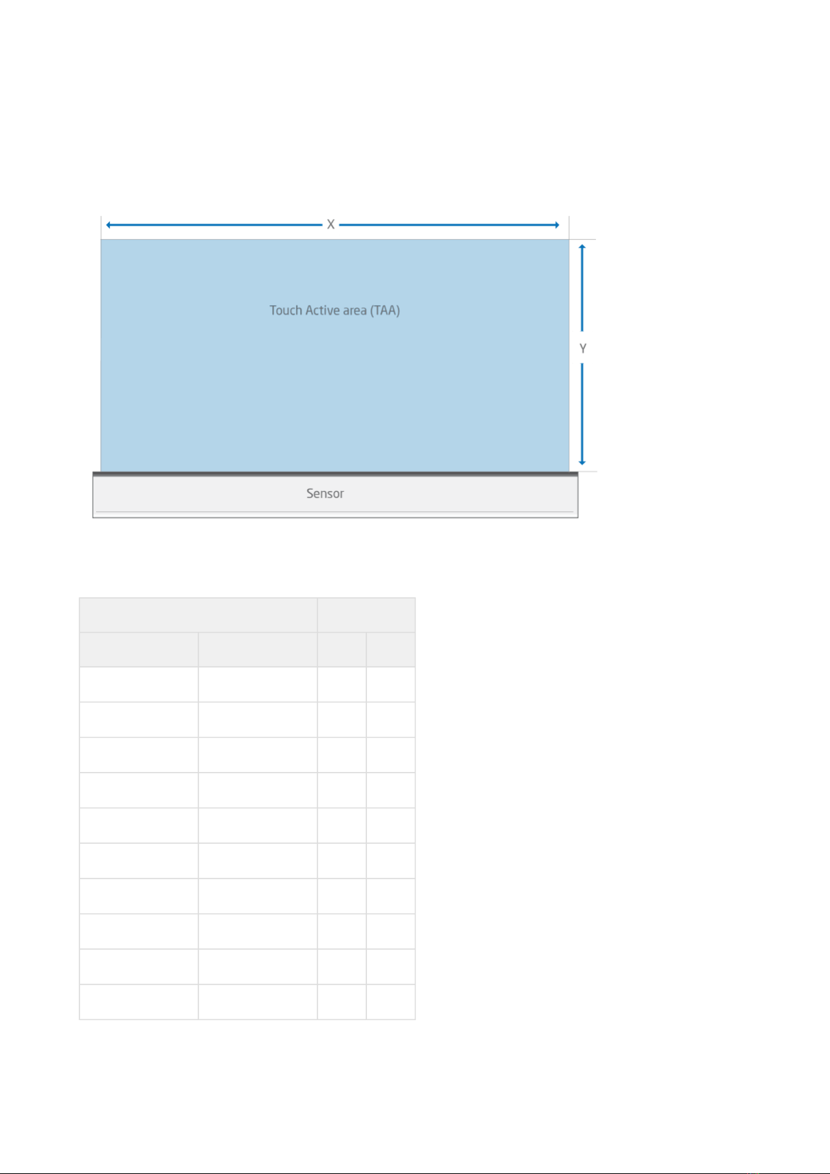
2.2.2 Sensor Length
The Touch Sensor is available in 43 different lengths. The length affects the Touch Active Area (TAA) in both X and Y
directions.
zForce AIR® Touch Sensor User's Guide Introduction
https://support.neonode.com 10
Touch Active Area
The table lists all product variants, the product number, and the TAA for each variant. See alsoPhysical Dimensions
and Position of Origin (see page 79).
Product number TAA (mm)
0° Type 90° Type X Y
NNAMC0430PC01 NNAMC0431PC01 43.2 14.9
NNAMC0500PC01 NNAMC0501PC01 50.4 29.8
NNAMC0580PC01 NNAMC0581PC01 57.6 29.8
NNAMC0640PC01 NNAMC0641PC01 64.8 44.7
NNAMC0720PC01 NNAMC0721PC01 72 44.7
NNAMC0790PC01 NNAMC0791PC01 79.2 59.6
NNAMC0860PC01 NNAMC0861PC01 86.4 59.6
NNAMC0940PC01 NNAMC0941PC01 93.6 74.5
NNAMC1010PC01 NNAMC1011PC01 100.8 74.5
NNAMC1080PC01 NNAMC1081PC01 108 89.4

zForce AIR® Touch Sensor User's Guide Introduction
https://support.neonode.com 11
Product number TAA (mm)
0° Type 90° Type X Y
NNAMC1150PC01 NNAMC1151PC01 115.2 89.4
NNAMC1220PC01 NNAMC1221PC01 122.4 104.3
NNAMC1300PC01 NNAMC1301PC01 129.6 104.3
NNAMC1370PC01 NNAMC1371PC01 136.8 119.2
NNAMC1440PC01 NNAMC1441PC01 144 119.2
NNAMC1510PC01 NNAMC1511PC01 151.2 134.0
NNAMC1580PC01 NNAMC1581PC01 158.4 134.0
NNAMC1660PC01 NNAMC1661PC01 165.6 148.9
NNAMC1730PC01 NNAMC1731PC01 172.8 148.9
NNAMC1800PC01 NNAMC1801PC01 180 163.8
NNAMC1870PC01 NNAMC1871PC01 187.2 163.8
NNAMC1940PC01 NNAMC1941PC01 194.4 178.7
NNAMC2020PC01 NNAMC2021PC01 201.6 178.7
NNAMC2090PC01 NNAMC2091PC01 208.8 193.6
NNAMC2160PC01 NNAMC2161PC01 216 193.6
NNAMC2230PC01 NNAMC2231PC01 223.2 208.5
NNAMC2300PC01 NNAMC2301PC01 230.4 208.5
NNAMC2380PC01 NNAMC2381PC01 237.6 208.5
NNAMC2450PC01 NNAMC2451PC01 244.8 208.5
NNAMC2520PC01 NNAMC2521PC01 252 208.5
NNAMC2590PC01 NNAMC2591PC01 259.2 208.5
NNAMC2660PC01 NNAMC2661PC01 266.4 208.5
NNAMC2740PC01 NNAMC2741PC01 273.6 208.5
zForce AIR® Touch Sensor User's Guide Introduction
https://support.neonode.com 12
Product number TAA (mm)
0° Type 90° Type X Y
NNAMC2810PC01 NNAMC2811PC01 280.8 208.5
NNAMC2880PC01 NNAMC2881PC01 288 208.5
NNAMC2950PC01 NNAMC2951PC01 295.2 208.5
NNAMC3020PC01 NNAMC3021PC01 302.4 208.5
NNAMC3100PC01 NNAMC3101PC01 309.6 208.5
NNAMC3170PC01 NNAMC3171PC01 316.8 208.5
NNAMC3240PC01 NNAMC3241PC01 324 208.5
NNAMC3310PC01 NNAMC3311PC01 331.2 208.5
NNAMC3380PC01 NNAMC3381PC01 338.4 208.5
NNAMC3460PC01 NNAMC3461PC01 345.6 208.5
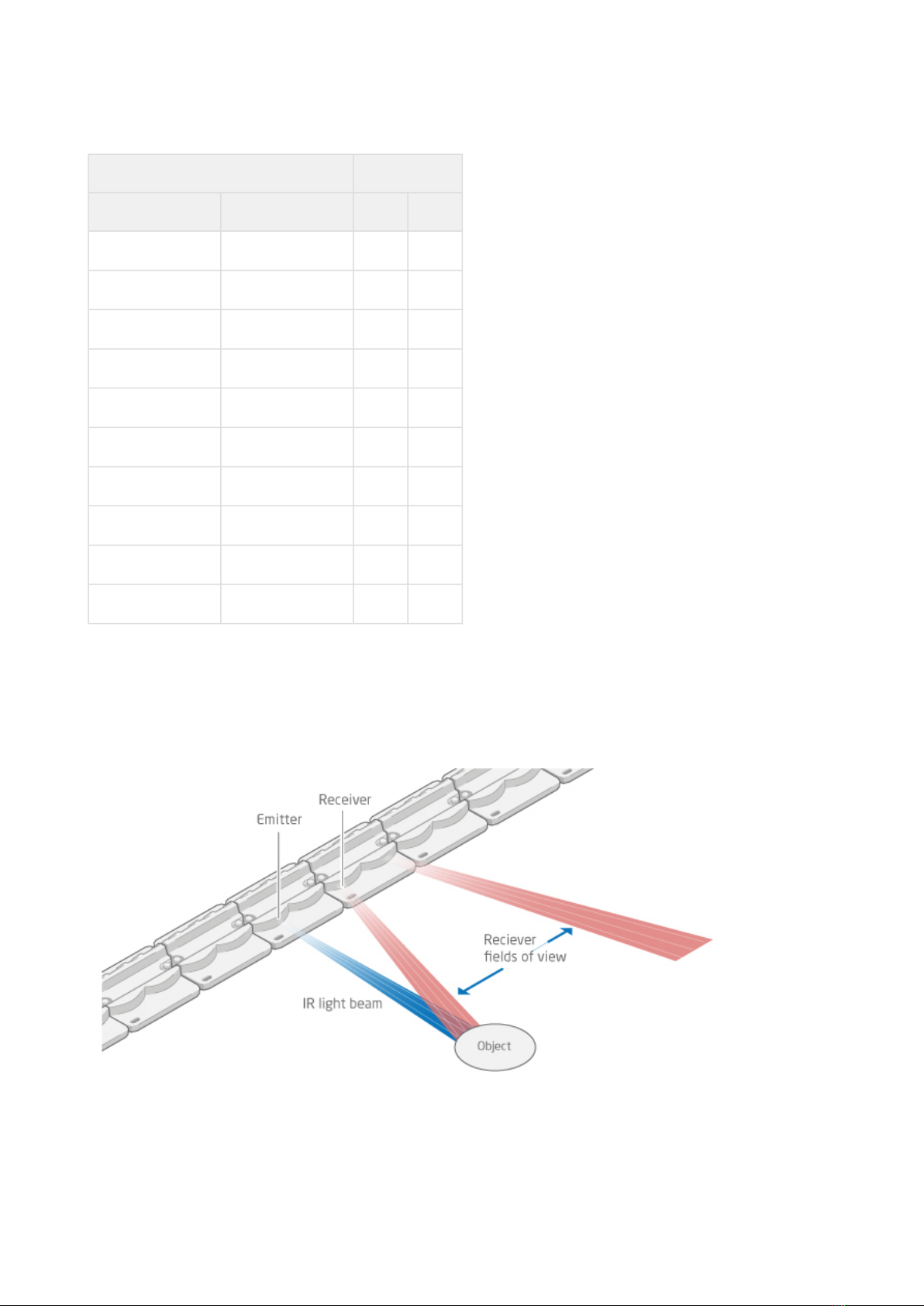
2.3 Basic Principles
zForce AIR Touch Sensors detect and trace objects by detecting diffusely reflected infrared light. The sensor
comprises an optical system arranged to combine emitted IR beams and receiver fields of view within the same
apertures. IR light beamsare emitted perpendicular to the output window, while receivers field of view is centered
at a certain angle left and right.
zForce AIR® Touch Sensor User's Guide Introduction
https://support.neonode.com 13
Each emitter-receivercombination covers a narrow region on the active area. An object present in the active area
will affect several emitter-receiver channels, and the reported coordinates is the outcome of a center of gravity
calculation on these signals.
2.4 Applications
zForce AIR Touch Sensors can be integratedfor a wide range of applications,such as:
•PCs/Tablets
•TVs/Monitors
•Printers
•Mechanical key replacement
•White goods
•Smart furniture
•Interactive mirrors
•Elevator panels
•eReaders
•Instruments
•Vending Machines
•ATM/POS terminals
•Robotics
•Range finders
•Collision detectors
•... and much more
2.5 Product Design and Components
The zForceAIR Touch Sensor isa laser light based touch sensor that can be used for various touch andmid-air
detectionapplications.The sensor is available in varying sizes, seeProduct Variants (see page 8).
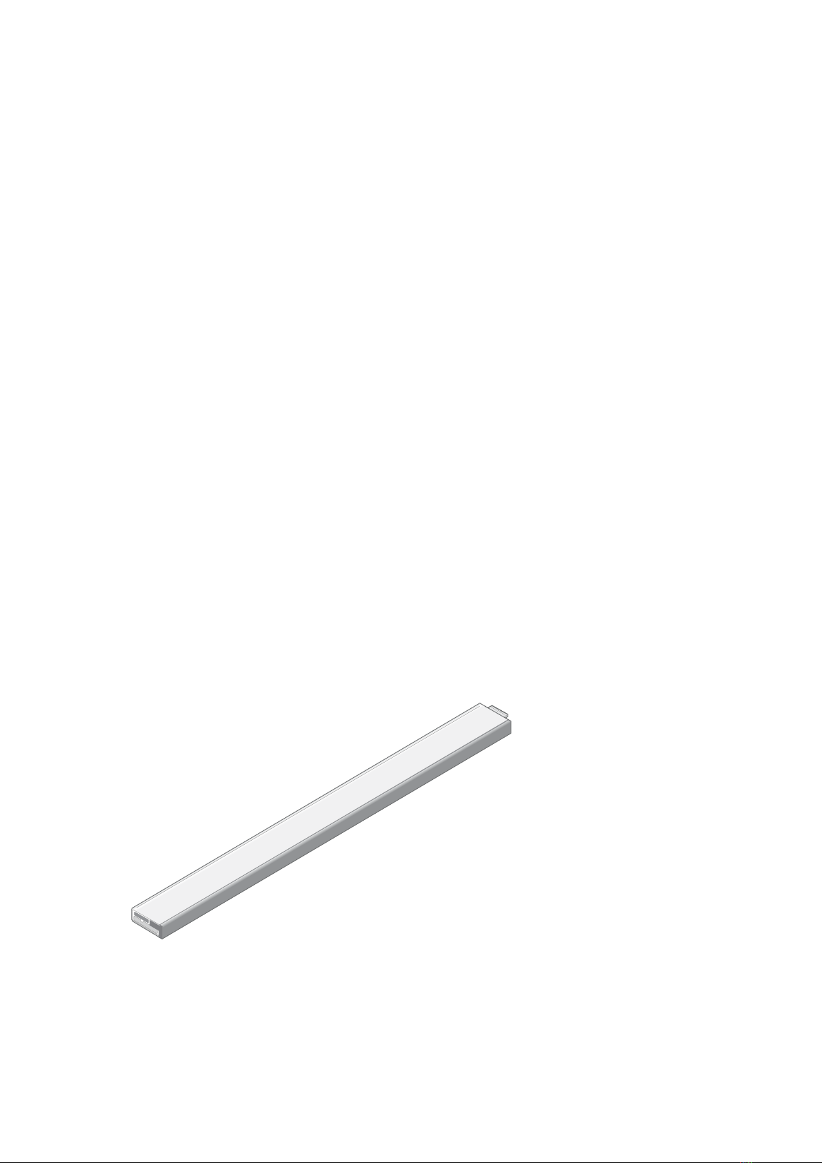
2.5.1 Sensor Design
The image below show the sensor design (0° type). The connector is shown to the far right.

zForce AIR® Touch Sensor User's Guide Introduction
https://support.neonode.com 14
Exploded view
The image below shows the sensor (0° type) in an exploded view.
Part Decription
A Cover
B Adhesive
C Front light pipe – straight shooting or 90 degree shooting depending on sensor type
D Lenses - amount depends on size
E PCBA

zForce AIR® Touch Sensor User's Guide Introduction
https://support.neonode.com 15
2.5.2 Sensor Components
The PCBA is equipped with both active and passive components, for example:
•MCU
•Co-processor, a Neonode proprietary scanning IC
•Optical lenses, made out of polycarbonate
•VCSELs
•Photodiodes
•Other passive components
2.6 Product Integration
The zForce AIR Touch Sensor can be integrated to any host system through a physical connector with 8 contact
padswith support for both I2C and USB HID. The host system can communicate with the sensorthrougha
communication protocol and an SDK developed by Neonode.
zForce AIR® Touch Sensor User's Guide Getting started with zForce AIR Touch Sensor Evaluation
https://support.neonode.com 16
3 Getting started with zForce AIR Touch Sensor Evaluation
This section describes how to get started with the evaluation of a zForce AIR Touch Sensor.
3.1 Evaluation Kit Contents
The evaluation kit includes the following:
•1 x zForce AIR Touch Sensor
•1 x Interface board (with USB and I2C interface)
•1 x FPC Cable with connector
3.2 Getting Started
1. Connect thesensor according to Connecting Sensor (see page 16).
2. Start communicating using one of the means listed below:
•Neonode Workbench (see page 19). Use the Neonode Workbench software for Windows to configure a sensor
and test and evaluate touch performance.
•USB HID Digitizer Mode (see page 19). This istheeasiest andfastest way to try out the Touch Sensor. It only
requires connecting the interface board to a Windows or Linux computervia USB, but is limited in
functionality.
•USB HID Raw Mode (see page 19). This also uses a USB connection to a Windows or Linux computer, but
requires communicating with the sensor using ASN.1 encoded messages.
•I2C Transport (see page 19). This involves sending and receivingASN.1 encoded messages over I2C.
•SDK (see page 19). Using the zForce SDK function library facilitates communication with sensors without
considering ASN.1 encoded messages.
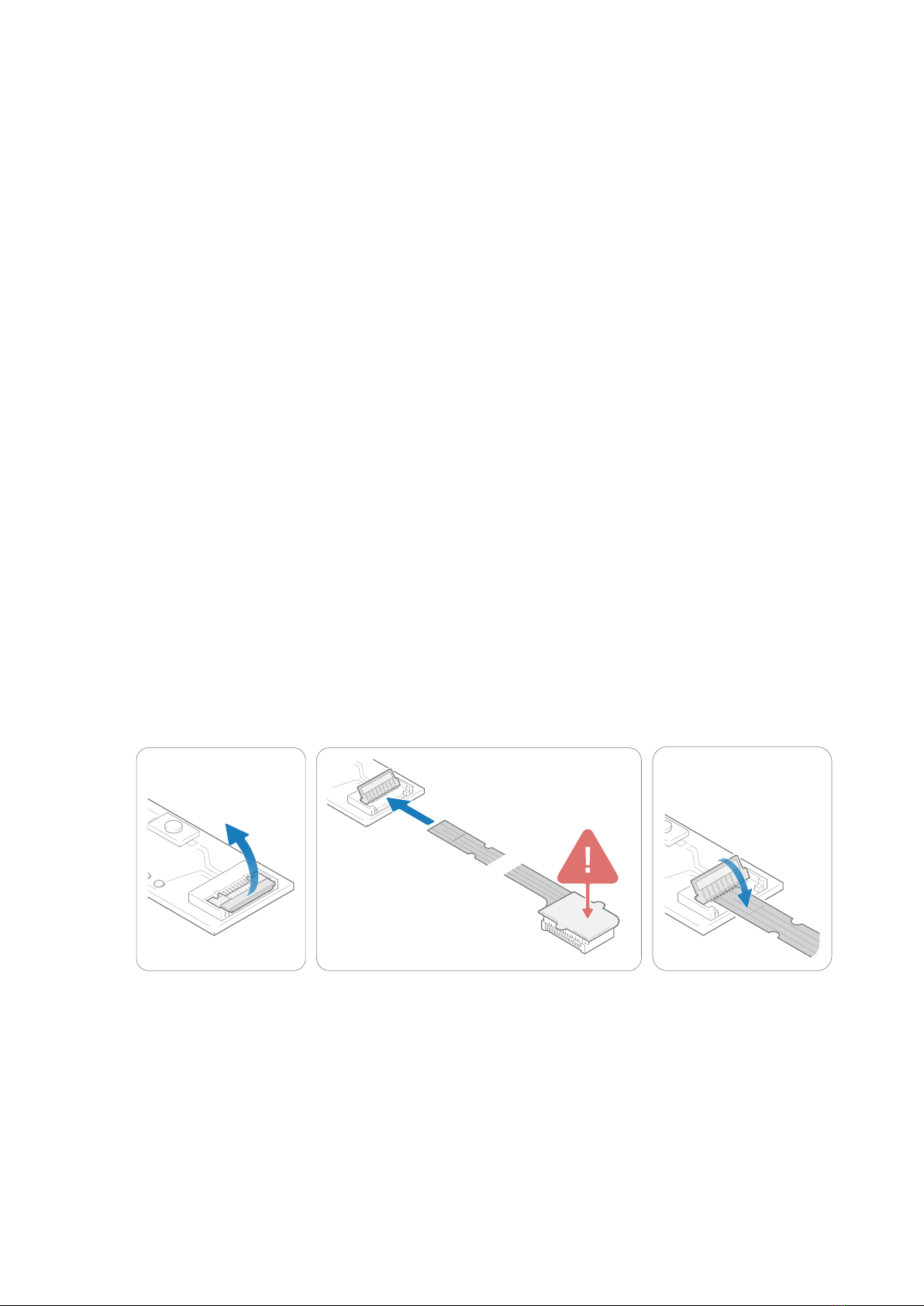
3.3 Connecting Sensor
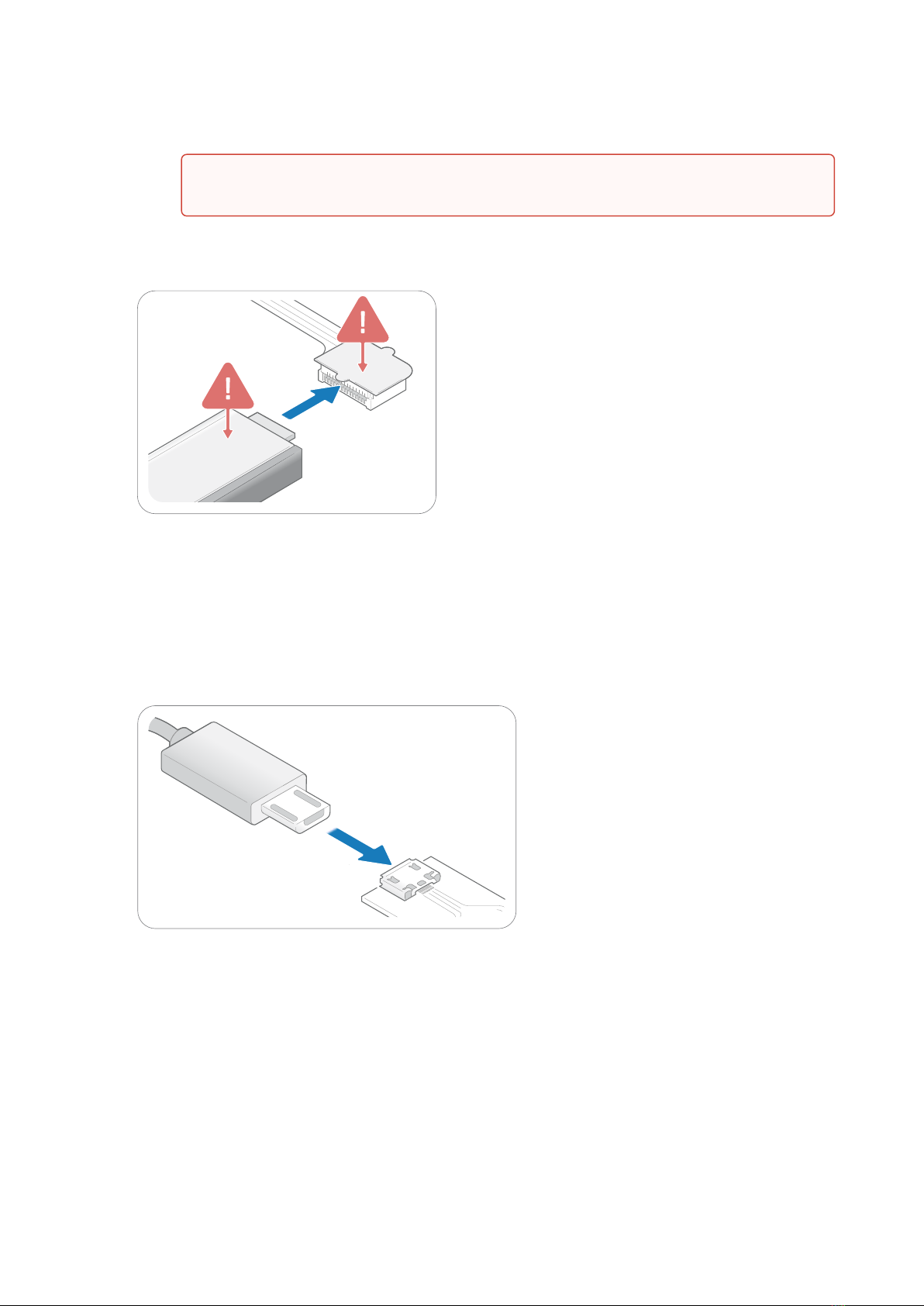
1. Connect the FPC cable to the interface board:
a. Lift the flip lock on the interface board.
b. Insert the FPCcable into the end of the connector, with the connector pads facing down,towards
interface board. Theyellow piece of PCB of the connector on the other side of the cable is facing
upwards. Make sure the direction is straight into the connector and the pads have reached the endof
the connector.
zForce AIR® Touch Sensor User's Guide Getting started with zForce AIR Touch Sensor Evaluation
https://support.neonode.com 17
c. Pressdown the flip lock.
2. Connect the FPC cable to the sensor:
a. Place the sensor so that the sensor connector pads of the sensor are facing downwards (steel surface
upwards).
b. Insert sensor into theconnector on FPC cable (yellow piece of PCB of the FPC connector still facing
upwards).
c. Make sure the direction of the pads is straight into the connector, and the pads have reached the
endof the connector.
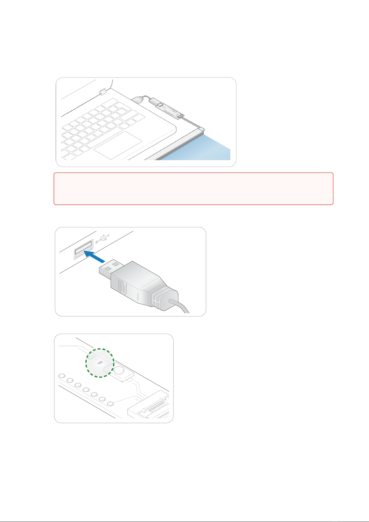
3. To use Neonode Workbench, USB HID Digitizer mode, USB HIDRaw mode, or SDK: Connect aUSBcable with
aMicro USB type B connector to the interface board.
4. Touse I2C Transport: Wire the pads of +5V, DR-B0, I2C-D, I2C-C, and GND on the interface board to the host
system. For details, refer to Electrical Integration (see page 29). Do not connect power until the following steps
have been performed.
Make sure the connector pads of the FPC cable are facing downwards,towards interface
board. The sensor risks damage if the FPC cable is connected in wrong direction.
zForce AIR® Touch Sensor User's Guide Getting started with zForce AIR Touch Sensor Evaluation
https://support.neonode.com 18
5. Place the sensor on a table with the steel surface facing downwards and with the optical surface facing
towards you.
6. To use Neonode Workbench, USB HID Digitizer mode, USB HIDRaw mode, or SDK: Insert the USB cable into
a computer meeting the requirements of USB HID or SDK, respectively.
C
7. To use I2C Transport: Connect the power to the sensor through the I2C.
8. The green LED on the interface board lights up when connected.
Make sure no object is within the touch active area of the sensor before connecting power to the
sensor through USB or I2C. The sensor calibrates itself when powered on and an object within the
touch active area may interfere with the calibration.

zForce AIR® Touch Sensor User's Guide Getting started with zForce AIR Touch Sensor Evaluation
https://support.neonode.com 19
2 https://support.neonode.com/docs/display/Downloads
3.4 Communicating with Sensor
3.4.1 Neonode Workbench
Neonode Workbench is a software toolto use with zForce AIR™sensors. With Neonode Workbench it is possible to:
• Visualizesensor touches.
•Temporarily configure sensor characteristics, such as active area and scanning frequency.
• Viewthe sensor firmware version.
•Conduct Open/Short-circuit tests to identify any damaged photo or laser diodes.
Download Neonode Workbench from Downloads2and refer to separate Neonode Workbench documentation.
3.4.2 USB HID Digitizer Mode
The easiest way to see the Touch Sensor functionality is to use USB HID Digitizer mode:
1. When the sensor has enumerated, it will act as a touch screen USB HID device.
2. Put an object in the touch active area, touch HID reports will be send to host.
For more information on USB HID Digitizer mode, refer to USB HID Transport (see page 44).
3.4.3 USB HID Raw Mode
In USB HID Raw Mode, communication with a Touch Sensor is performed by sending and receiving messages as
reports defined by the USB HID standard.
To start communicating, perform the following:
1. When the sensor has enumerated, startcommunicatingas defined in USB HID Transport (see page 44). The
messages are encoded with ASN.1.Refer to Presentation Layer (ASN.1) (see page 57).
2. The Touch Sensor starts sending touch notifications once it is initialized. For initialization procedures, refer
toInitializing Sensors (see page 36).
3.4.4 I2C Transport
To start communicating, perform the following:
1. Send or read data over the I2C bus. Refer to I2C Transport (see page 41). The messages are encoded with ASN.
1. Refer to Presentation Layer (ASN.1) (see page 57).
2. The sensor starts sending touch notifications once it is initialized. For initialization procedures, refer to
Initializing Sensors (see page 36).
3.4.5 SDK
To start communicating, follow theGetting Started instructions in the separate SDK documentation.
In case of strong side light, covering the short sides of the sensor with, for example,black tapemight
improve performace.

zForce AIR® Touch Sensor User's Guide Getting started with zForce AIR Touch Sensor Evaluation
https://support.neonode.com 20
Table of contents
Other NEONODE Accessories manuals


