C A U T I O NC A U T I O N !
SUBJECT TO ELECTROSTATIC DAMAGE
OR DECREASE IN RELIABILITY.
HANDLING PRECAUTIONS REQUIRED.
Warranty: ADTRAN will replace or repair this product within the warranty period if it does not
meet its published specifications or fails while in service. Warranty information can be
found online at www.adtran.com/warranty.
Trademarks: Brand names and product names included in this document are trademarks,
registered trademarks, or trade names of their respective holders.
©2016 ADTRAN, Inc. All Rights Reserved.
ADTRAN CUSTOMER CARE:
From within the U.S. 1.800.726.8663
From outside the U.S. +1 256.963.8716
PRICING AND AVAILABILITY 1.800.827.0807
*61287783F1-22A*
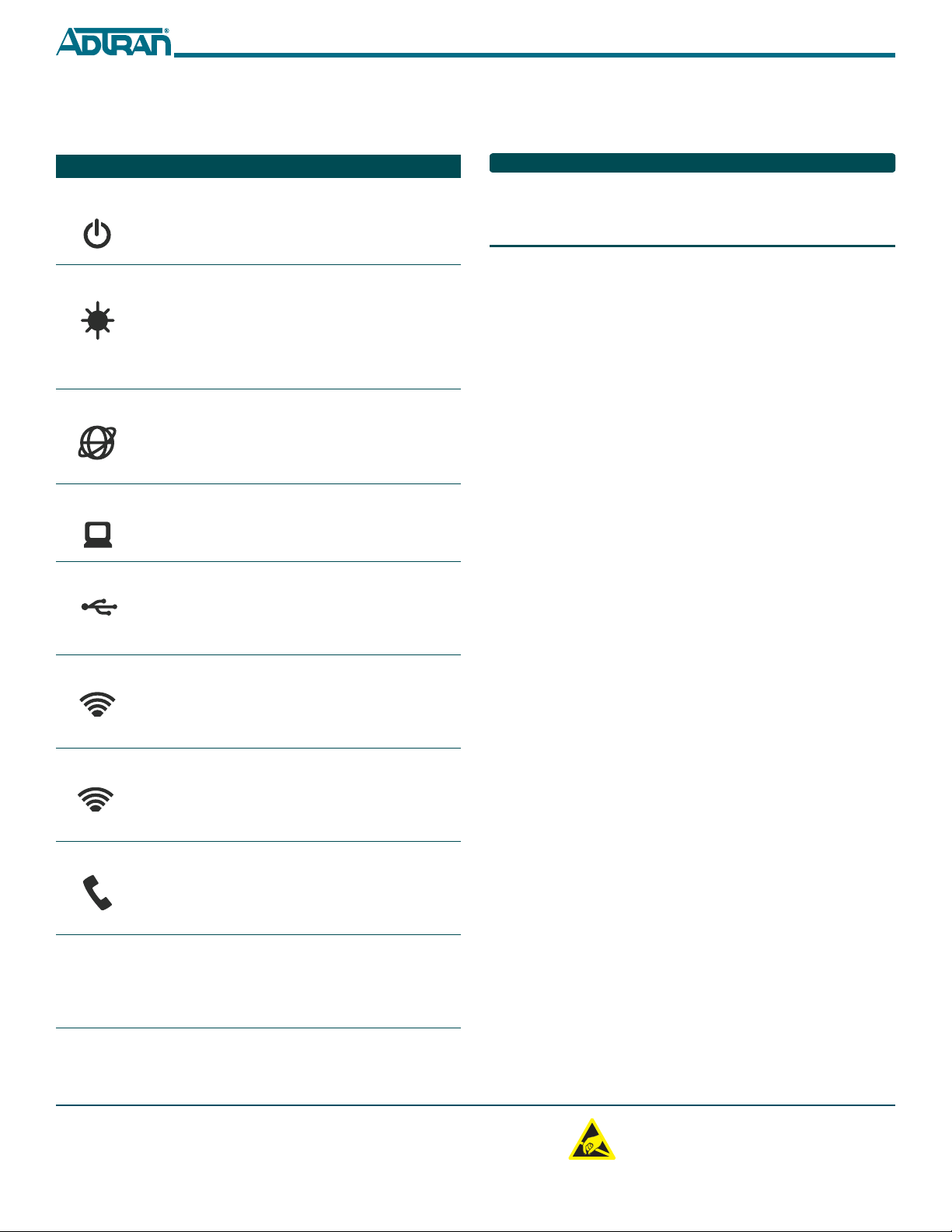
LED STATUS
The following table provides the LED status during normal opera-
tions.
Label Status Indication
POWER
Off
Green
AC or battery off
No Failure
FIBER
2
Off
Green
Green Flashing
Fast
No connection to the OLT,
open fiber, failure at the ONT,
or power is Off
DS signal present and is within
operating range
Ranging in Progress
INTERNET
Off
Green
No IP address configured on
WAN Interface, or Power is
Off
WAN Interface is configured
with IP address
GE 1-4
2
Off
Green
Green Flashing
Fast
Link is down or not equipped
Link is up
Data is being sent or received
USB
2
Off
Green
Green Flashing
Fast
Power Off or no device con-
nected
Device connected
Data is being sent or received
2.4 GHZ
2
Off
Green
Green Flashing
Fast
Power is Off, or Wireless
2.4GHz is Disabled
Wireless 2.4GHz is Enabled
Data is being sent or received
on 2.4GHz
5.0 GHZ
2
Off
Green
Green Flashing
Fast
Power is Off, or Wireless 5GHz
is Disabled
Wireless 5GHz is Enabled
Data is being sent or received
on 5GHz
PHONE 1-2
2
Off
Green
Green Flashing
Slow
Unequipped or on-hook and
not ringing
Line is off-hook
Line in ringing state
WPS
2
Off
Green
Green Flashing
Fast
Power Off or WPS is Disabled
WPS is Enabled
WPS push button pressed and
device is ready to accept con-
nection
REGISTRATION ID
Registration ID is performed by Serial Number Activation. This
occurs when the 424RG3 ONT is “Discovered” by the OLT.
If AOE Auto Upgrade is active, a new 424RG3 ONT installation will
be detected and a fast blinking FIBER LED will indicate a new
software download has commenced. This may take 5 - 10 minutes to
complete.
SPECIFICATIONS
Refer to the following for a list of all specifications for the 424RG3
ONT.
■Electrical
♦Voltage: 12 Volts typical
♦Minimum Voltage: 10 Volts
♦Maximum Voltage: 13.9 Volts
♦Power Consumption: Typical 25.0 watts
■Physical
♦10.8 inches high (27.5 centimeters)
♦7.4 inches deep (18.8 centimeters)
♦3.2 inches wide (8.1 centimeters)
♦Weight: 1 pounds (0.45 kilograms)
■Environmental
♦Operational Temperature: 32°F to 104°F (0°C to +40°C)
♦Storage Temperature: –4°F to 122°F (–20°C to +50°C)
♦Relative Humidity: 90%, noncondensing
■Optical
♦TX min power: +0.5 dBm
♦TX max power: +5.0 dBm
♦RSSI max sensitivity: –27.0 dBm
♦R.0X overload: –8.0 dBm
♦TX wavelength: 1310 nm typical
♦RX wavelength: 1490 nm typical
MAINTENANCE
The 424RG3 ONT does not require routine hardware maintenance for
normal operation. ADTRAN does not recommend that repairs be
attempted in the field. Repair services may be obtained by returning
the defective unit to ADTRAN. Refer to the warranty for further
information. Field support for software is provided through upgrade
facilities.
SAFETY AND REGULATORY COMPLIANCE
Refer to the Safety and Regulatory Compliance Notice for this
product (P/N 61287783F1-17) for detailed safety and regulatory
information.
Consultez l'avis sur la sécurité et la conformité à la réglementation
pour ce produit (61287783F1-17) pour obtenir des renseignements
détaillés sur la sécurité et la réglementation.