suprema Xpass User manual

English
Version 2.00
Xpass
INSTALLATION GUIDE
www.supremainc.com
EN 101.00.XPS V2.00A

Contents
Safety Instructions ..........................................................................................3
Getting Started ................................................................................................4
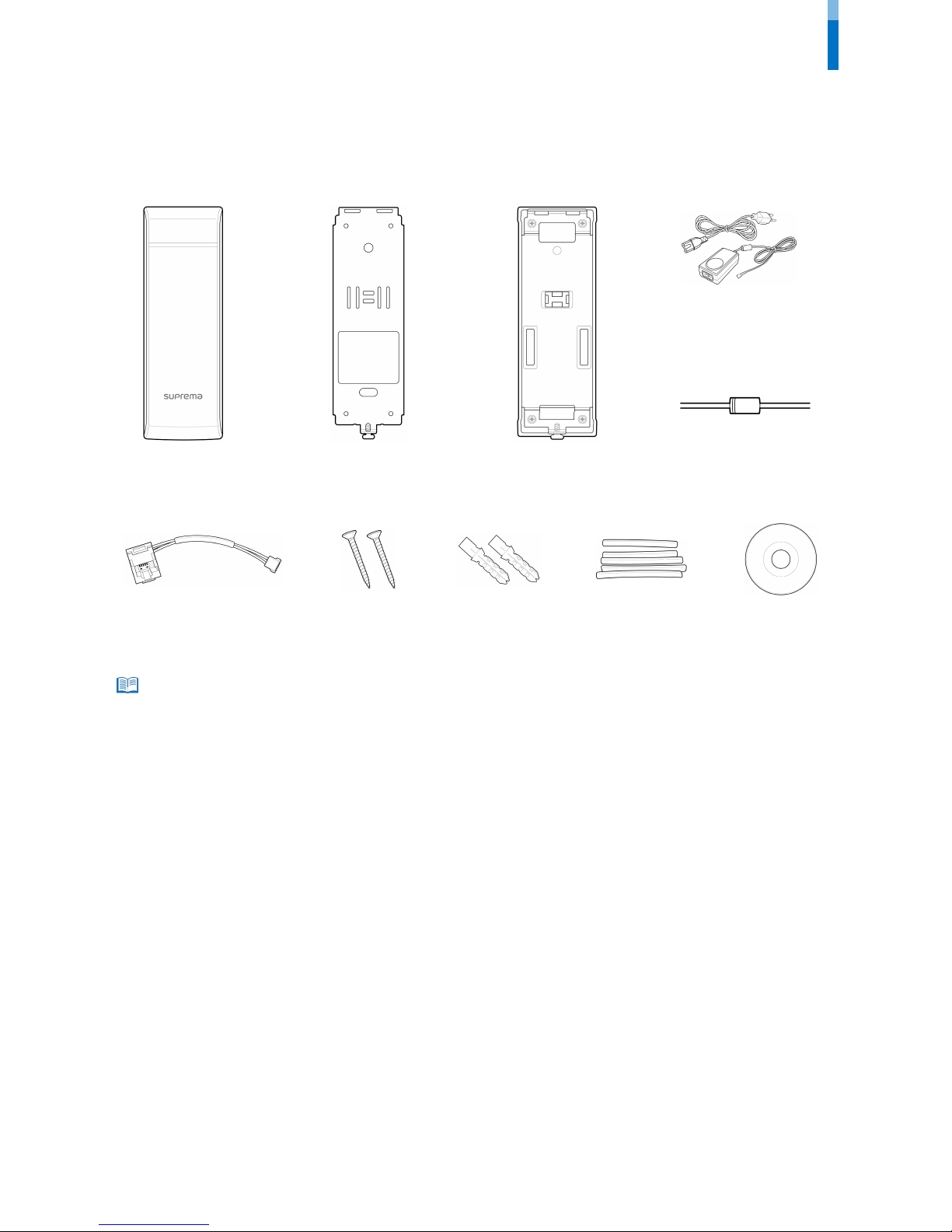
Components ...................................................................................................................................................4
Features ..........................................................................................................................................................5
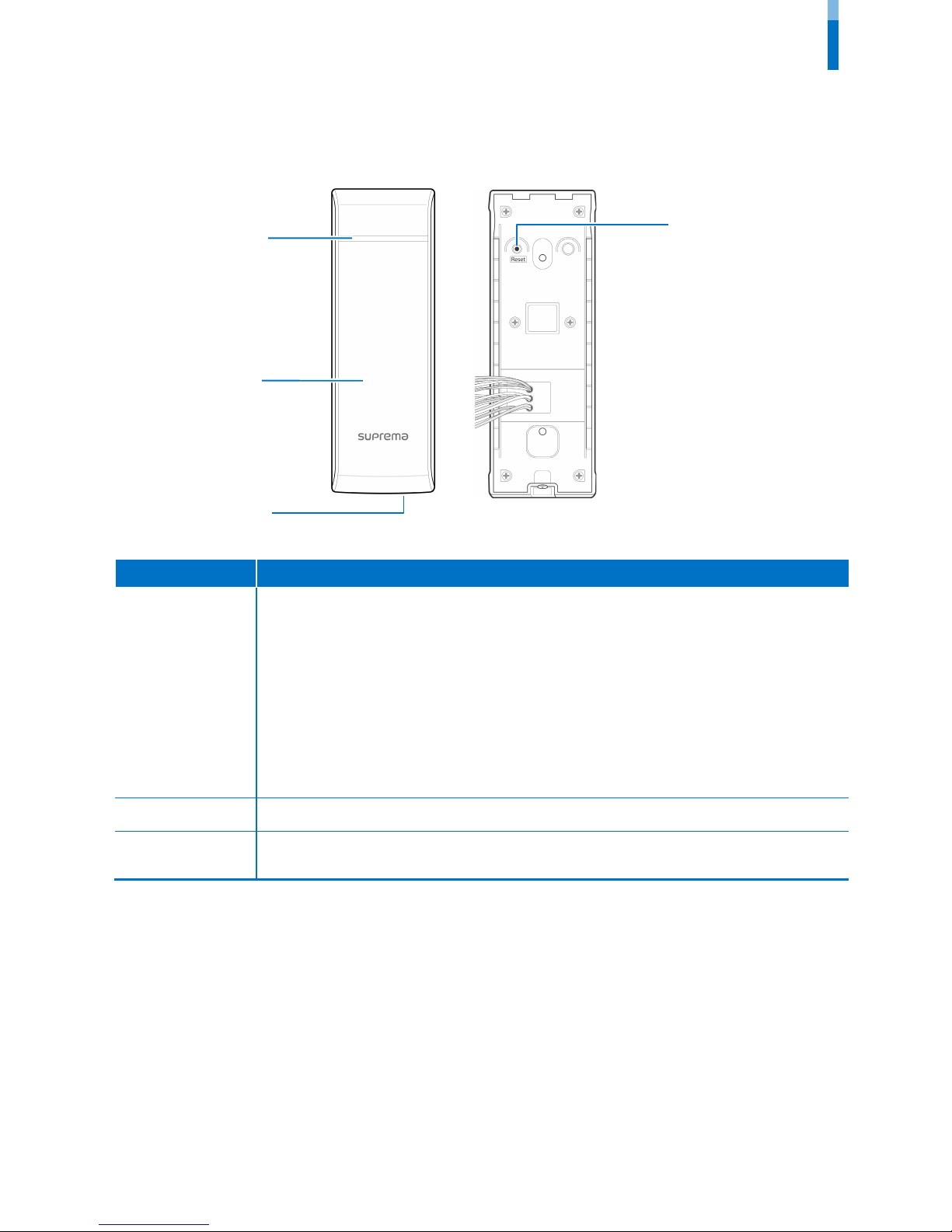
Part names and features ..................................................................................................................................................5
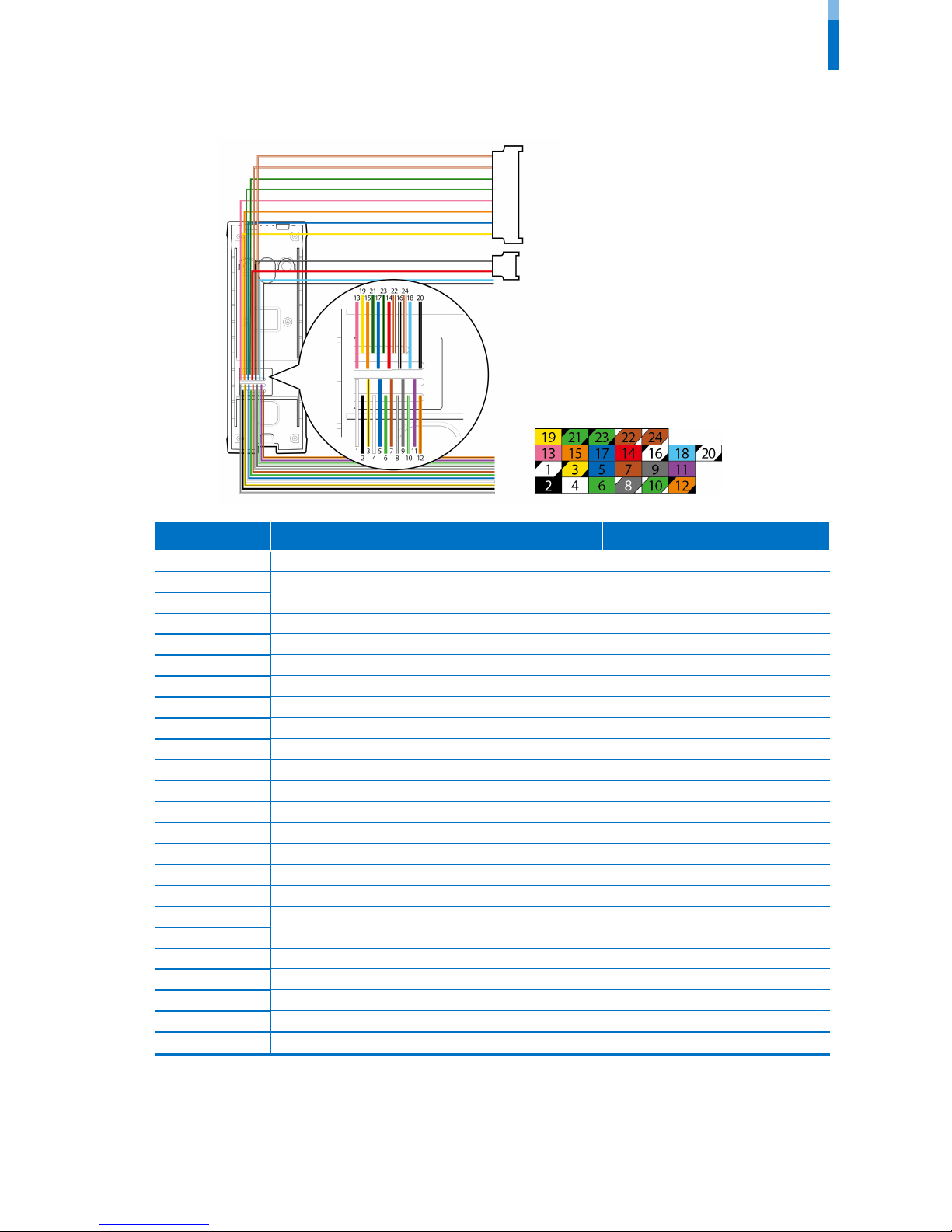
Cables and connectors ......................................................................................................................................................6
Installation ........................................................................................................7
Mounting the Bracket and Product ...........................................................................................................7
Installing the bracket.........................................................................................................................................................7
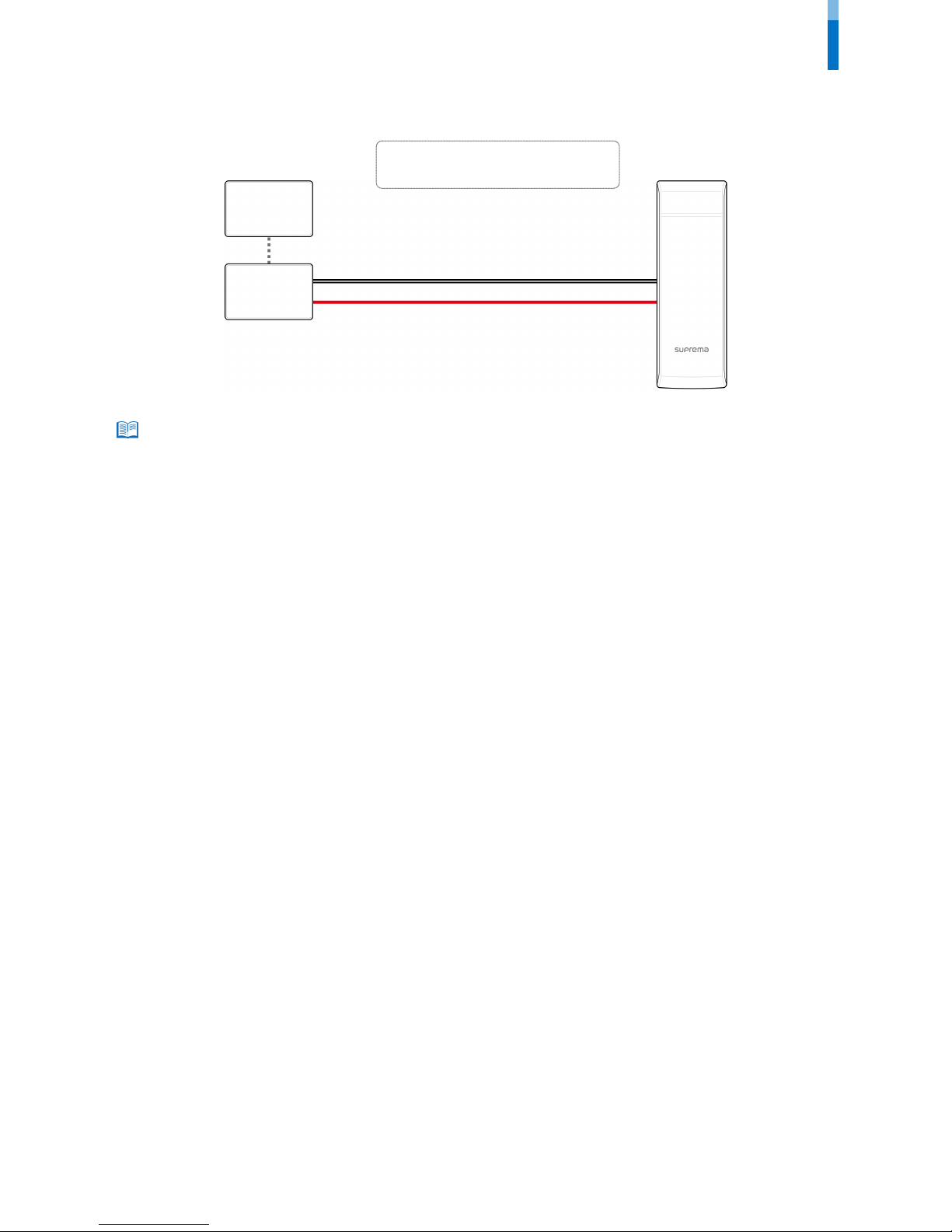
Connecting to Power....................................................................................................................................8
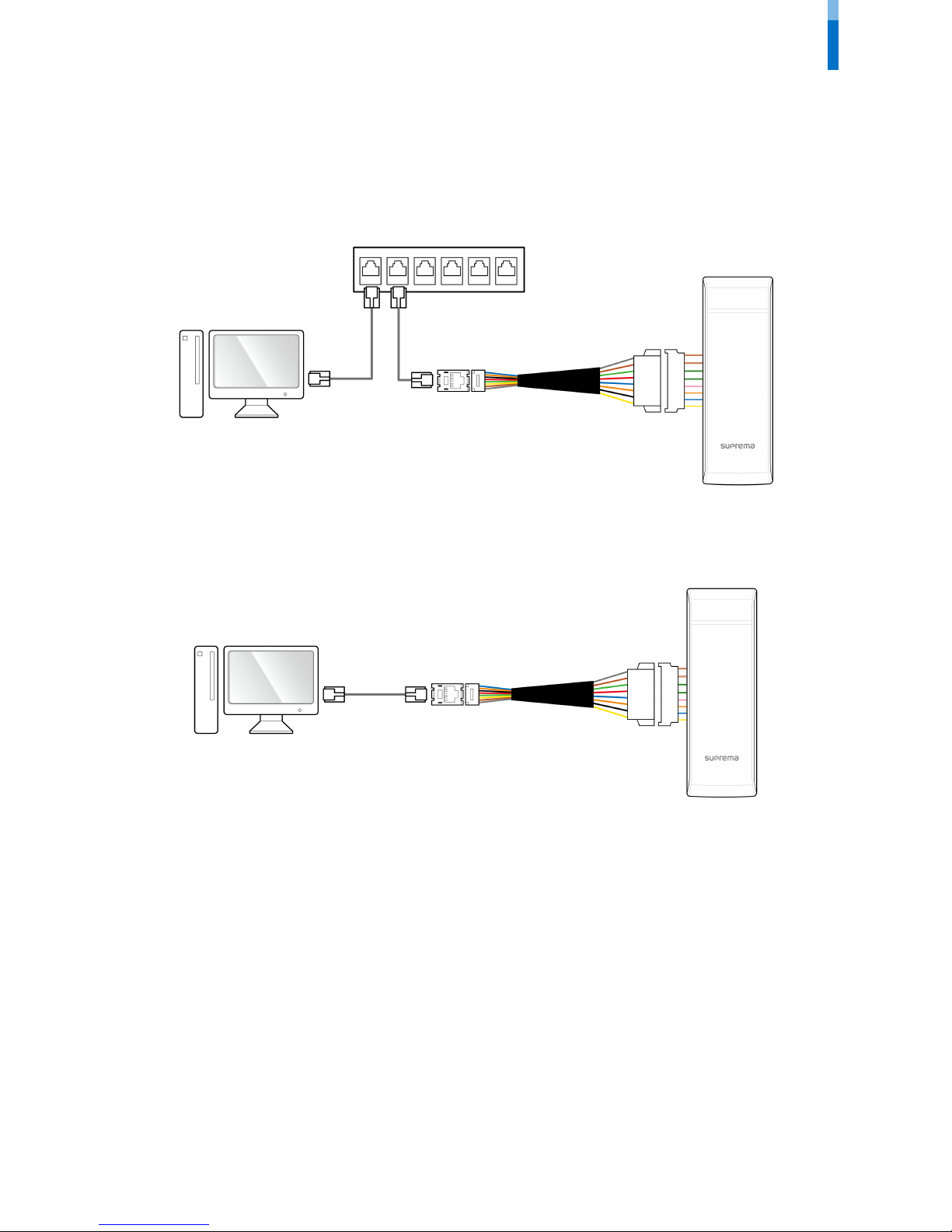
Connecting to a Network ............................................................................................................................9
TCP/IP ....................................................................................................................................................................................9
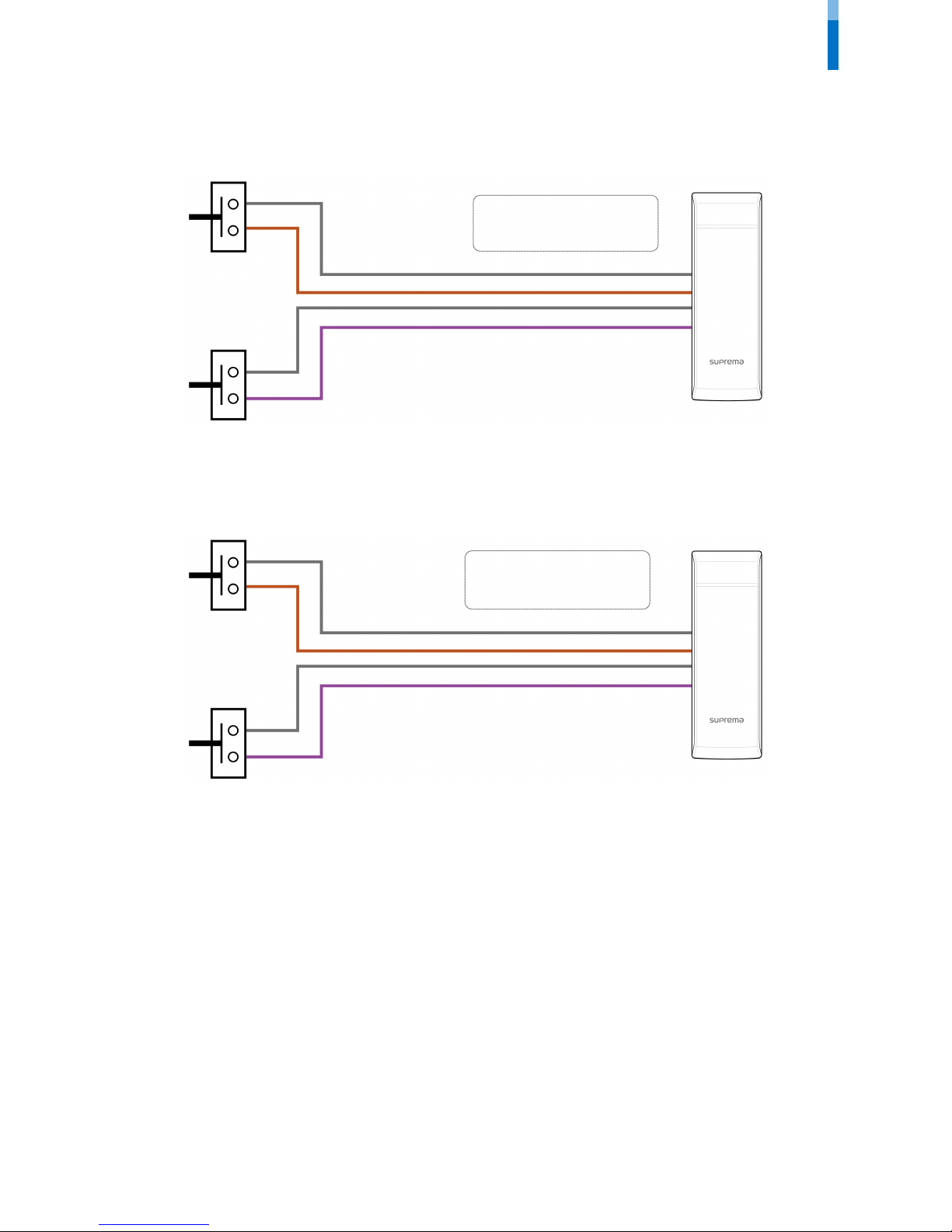
Connecting to an Door button/Door sensor ...........................................................................................10
Digital input connection (Door button, Door sensor) .............................................................................................10
Digital input connection (Alarm, Emergency switch)...............................................................................................10
Connecting to a Relay ...............................................................................................................................11
Fail Safe Lock ....................................................................................................................................................................11
Fail Secure Lock ................................................................................................................................................................11
Connecting to an Automatic door................................................................................................................................12
Connecting as a standalone......................................................................................................................12
Connecting to Secure I/O 2 ......................................................................................................................13
Connecting as a Wiegand device.............................................................................................................13
Output ..........................................................................................................................................................14
Resetting Network Settings.........................................................................................................................14
Product Specifications ................................................................................. 15
Product Specifications ................................................................................................................................15
Dimensions...................................................................................................................................................16
FCC Compliance Information....................................................................... 17
Appendix ........................................................................................................ 18
Disclaimers ...................................................................................................................................................18
Copyright Notice .........................................................................................................................................18

Safety Instructions
Safety Instructions
Please read the following instructions carefully before using the product. This information is important for ensuring the safety of the user
and for preventing damage to the user's property.
Warning
Violation of the instructions may cause serious injury or death.
Installation Instructions
Do not install the product in direct sunlight or in a location that is damp or dusty.
•This can cause a fire or electric shock.
Install the product in a dry place.
•Moisture can cause product damage or electric shock.
Do not install the product near any heat source such as electric heaters.
•This can cause a fire from overheat or electric shock.
Install the product in a place where there is no electromagnetic interference.
•This can cause product damage or electric shock.
Have qualified service professionals install or repair the product.
•Otherwise, it can cause a fire, electric shock, or injury.
•If the product is damaged due to a user's unauthorized installation or dismantling of the product, a service fee will be charged for repair.
Operating Instructions
Be careful not to spill any liquid such as water, drinks, or chemicals inside the product.
•This can cause fire, electric shock, or product damage.
Caution
Ignoring these instructions may result in minor injuries or damage to the product.
Installation Instructions
Protect the power cord from being walked on or pinched.
•This can cause product damage or injury.
Keep the product away from strong magnetic objects such as magnets, TVs, monitors (especially CRT monitors), or speakers.
•This can cause a product failure.
If you install the product at fully exposed outdoor, it is recommended to install the enclosure.
Secure I/O 2, the electrical locking device and this product must use independent power source.
Operating Instructions
Do not drop the product or subject it to shock or impact during use.
•This can cause a product failure.
Do not press the buttons on the product with excessive force or with a sharp tool.
•This can cause a failure.
Clean the product with a soft, dry cloth. Do not use alcohol, benzene, or water.
•This can cause a product failure.
3

Getting Started
Getting Started
Components
The components may differ depending on where the product is installed.
Note
Xpass
Main bracket
Adapter
Mounting screws for bracket
(2 pcs)
PVC anchors
(2 pcs)
Heat shrink
tubes
Software CD
Diode
Extension bracket
TCP/IP
extension cable
4

Getting Started
Features
Part names and features
Name Feature
LED lamp
•Green: Authentication success
•Red: Authentication failure
•Pink: Processing
•Blue and sky-blue alternate flashing every 2 seconds: Normal operation
•Red and pink alternate flashing every 2 seconds: The device is locked.
•Blue and red alternate flashing every 2 seconds: The clock has been reset due to an empty internal battery.
(The clock needs to be reconfigured.)
•Blue and yellow alternate flashing every 2 seconds: An IP address has not been received when DHCP is set
to USE.
•Red flashes every 2 seconds on first use: Failure to reset. Contact the manufacturer.
•Red flashes every 2 seconds in a normal operation: The device is secured.
•Yellow flashes: Waiting for an input.
RF card touch area Reads RF card for entering and exiting.
Network reset button Resets the network configurations when the device does not work properly. For details, refer to the Resetting
Network Setting.
RF card touch area
LED lamp
Network reset button
Ethernet LED
5

Getting Started
Cables and connectors
Pin Pin name Color
1 RS-485 GND White (Black stripe)
2 Wiegand GND Black
3 RS-485 TRX- Yellow (Black stripe)
4 Wiegand Data 1 White
5 RS-485 TRX + Blue (White stripe)
6 Wiegand Data 0 Green
7 Switch Input 1 Brown
8 Normally Open Gray (White stripe)
9
Switch Input GND
Gray
10 Common Green (White stripe)
11 Switch Input 0 Purple
12
Normally Closed
Orange (Black stripe)
13 ETH TX+ Pink
14 Power In + Red
15
ETH TX-
Orange
16 PWR IN- Black (White stripe)
17 ETH RX+ Blue
18 Power Out + Sky-blue
19 ETH RX- Yellow
20 Power In - Black (White stripe)
21 VB1 Green (Black stripe)
22 VB2 Brown (White stripe)
23 VB1 Green (Black stripe)
24 VB2 Brown (White stripe)
6

Installation
Installation
Mounting the Bracket and Product
Installing the bracket
1With the mounting screws for the bracket, mount the bracket firmly onto the surface where Xpass is to be installed.
If Xpass should be installed onto a concrete wall, make a hole with a drill, and then insert a PVC anchor into the hole before screwing the mounting
screw.
2Attach Xpass onto the mounted bracket.
3Assemble Xpass with the bracket by screwing the mounting screws on the bottom of Xpass.
Note
7

Installation
Connecting to Power
•Use a power adapter that has a DC 12 V (± 10%) specification of with the minimum current of 1,500 mA and has IEC/EN 60950-1 certification. If the
power adapter is shared by other devices, the power adapter should provide a current more than the sum of the power consumption from this
device (1,500 mA) and other devices.
•Secure I/O 2, the electrical locking device and this product must use independent power source.
Note
14 - Power 12 V Red
16 - Power GND Black (White stripe)
UPS
(Optional)
DC power
Xpass
16
14
8

Installation
Connecting to a Network
TCP/IP
LAN connection (connecting to a hub)
A normal CAT-5 cable can be used to connect to a hub.
LAN connection (connecting directly to a PC)
Xpass can be connected directly to a PC by using a normal type CAT-5 cable because it supports an automatic MDI/MDIX function.
Xpass
PC
Xpass
Hub
PC
9

Installation
Connecting to an Door button/Door sensor
Digital input connection (Door button, Door sensor)
Digital input connection (Alarm, Emergency switch)
Xpass
Input 1
9
7
9
11
Input 0
7 - Switch Input 1 Brown
9 - Switch GND Gray
11 - Switch Input 0 Purple
Xpass
Door sensor 9
7
9
11
Door button
7 - Switch Input 1 Brown
9 - Switch GND Gray
11 - Switch Input 0 Purple
10

Installation
Connecting to a Relay
Fail Safe Lock
To use fail safe lock, connect N/C terminal as shown below. Normally, there is a current flowing through the relay and the door is opened
when the relay is activated by blocking current flows. The door is opened when there is a blackout or power failure caused by external
conditions.
•Install the diode at both ends of the wire for the door lock device as shown in the figure to protect the relay from being damaged by the reverse
current induced when the door lock device operates.
•Make sure that the direction of the installed diode is correct.
•Install the diode close to the door lock device.
•Use a separate power source for Xpass from the door lock device.
Fail Secure Lock
To use fail secure lock, connect N/O terminal as shown below. Normally, there is no current flowing through the relay and the door is
opened when the relay is activated by a current flows. The door is locked when there is a blackout or power failure caused by external
conditions.
•Install the diode at both ends of the wire for the door lock device as shown in the figure to protect the relay from being damaged by the reverse
current induced when the door lock device operates.
•Make sure that the direction of the installed diode is correct.
•Install the diode close to the door lock device.
•Use a separate power source for Xpass from the door lock device.
Note
8 - Normally Open Gray (White stripe)
10 - Common Green (White stripe)
Xpass
8
10
Deadbolt /
Door strike DC power
Note
10 - Common Green (White stripe)
12 - Normally Closed Orange (Black stripe)
Xpass
Deadbolt /
Door strike DC power
10
12
11

Installation
Connecting to an Automatic door
Connecting as a standalone
Door button
Door sensor
Door lock
Input 1
Relay
Input 0
9
7
12
10
9
11
Xpass
9 - Switch GND Gray
11 - Switch Input 0 Purple
7 - Switch Input 1 Brown
10 - Common Green (White stripe)
12 - Normally Closed Orange (Black stripe)
PC
8 - Normally Open Gray (White stripe)
10 - Common Green (White stripe)
Xpass
Sensor
Automatic door
controller
Door button
Door lock
8
10
12

Installation
Connecting to Secure I/O 2
Refer to the following figure for connecting.
•RS-485 should be AWG24, twisted pair, and maximum length is 1.2 km.
•Connect a termination resistor (120Ω) to both ends of a RS-485 daisy chain connection. It should be installed at both ends
of the daisy chain. If it is installed in the middle of the chain, the performance in communicating will deteriorate because it
reduces the signal level.
•Up to 32 devices can be connected via daisy chain (1 master device and 31 other devices).
Connecting as a Wiegand device
RFID reader
2 - Wiegand GND Black
4 - Wiegand Data 1 White
6 - Wiegand Data 0 Green
2
4
6
2
4
6
Controller
Xpass
Xpass
Door lock
Input 1
Door button
Door sensor
Input 0
5
3
1
1 - RS-485 GND White (Black stripe)
5 - RS-485 TRX+ Blue (White stripe)
3 - RS-485 TRX- Yellow (Black stripe)
PC
Xpass
Secure I/O 2
13

Installation
Output
•The external output provides a maximum current of 700 mA.
Resetting Network Settings
1Turn the power on.
2Press the network reset button on the rear of device until the device restart automatically.
3Connect the device with default values.
•TCP/IP address: 192.168.0.1
•Server mode: Not checked
•RS-485: PC connection, 115200 bps
4Change the TCP/IP address or RS-485 information.
5Turn the power off later on and then check the network setting is properly.
Note
10 - Common Green (White stripe)
12 - Normally Closed Orange (Black stripe)
18 - Power Out+ Sky-blue
20 - Power Out- Black (White stripe)
Xpass
Deadbolt /
Door strike
10
12
18
20
14

Product Specifications
Category Feature Specification
Main
IP Rating IP 65
RF Card 125KHz EM, 125KHz HID Prox, 13.56MHz Mifare/DESFire
Multi-Controller Yes (RF)
Capacity
Max. User (1:1) 40,000
Max. User (1:N) 40,000
Max. Text Log 50,000
Interface
TCP/IP Yes
RS-485 1ch
Wiegand 1ch In or Out (Selectable)
TTL Input 2 Inputs
Relay 1 Relay
Relay
Voltage Max. 24VDC
Current Typ. 0.5A, Max. 1.0A
Hardware
CPU 533MHz DSP
Memory 16MB RAM + 8GB Flash
LED Multi-Color
Sound 16-bit Hi-Fi
Operating Temp. -20°C ~ 50°C
Tamper Yes
Power 12VDC
PoE Optional
Dimensions (W x H x D mm) 45 x 130 x 27
Certification CE, FCC, MSIP(KCC), RoHS
15

Product Specifications
Dimensions
(Unit: mm)
Front view
Extension bracket
Main bracket
Side view
16

FCC Compliance Information
THIS DEVICE COMPLIES WITH PART 15 OF THE FCC RULES.
Operation is subject to the following two conditions:
(1) This device may not cause harmful interference, and
(2) This device must accept any interference received, including interference that may cause undesired operation.
Note: This equipment has been tested and found to comply with the limits for a Class B digital device, pursuant to part 15 of the FCC Rules.
These limits are designed to provide reasonable protection against harmful interference in a residential installation. This equipment
generates, uses, and can radiate radio frequency energy and, if not installed and used in accordance with the instructions, may cause
harmful interference to radio communications. However, there is no guarantee that interference will not occur in a particular installation. If
this equipment does cause harmful interference to radio or television reception, which can be determined by turning the equipment off
and on, the user is encouraged to try to correct the interference by one or more of the following measures:
•Reorient or relocate the receiving antenna.
•Increase the separation between the equipment and receiver.
•Connect the equipment into an outlet on a circuit different from that to which the receiver is connected.
•Consult the dealer or an experienced radio/TV technician for help.
Modifications not expressly approved by the manufacturer could void the user's authority to operate the equipment under FCC rules.
17

Appendix
Appendix
Disclaimers
This document provides the information pertaining to Suprema's products. The right of use is granted only to the products that are covered
by the sales agreement and conditions guaranteed by Suprema. Any license of intellectual property that is not dealt within this document
is not granted.
Suprema does not provide any warranty or liability of fitness or merchantability for a particular purpose and of infringement of patents,
copyrights, or other intellectual properties, regarding the sales or use of Suprema's products.
Do not use Suprema's products in either circumstances where people could be hurt or die as a consequence of malfunctions of the
products or circumstances related to medical treatments, the rescue of lives, or life supports. If a user suffers an accident in one of the
circumstances mentioned above, employees, subsidiaries, branches, partners, and distributors of Suprema are exempt from liability even
when it is claimed that there is a significant fault in the design or production process, and also they are not liable for any direct or indirect
cost or expenditure including legal costs.
Suprema can change the standard and specification of its products anytime without notice in order to improve the stability, functions, or
design of the products. Designers should keep in mind that the functions or explanations denoted as "to be implemented" or "not defined"
can be changed anytime. Suprema will implement or define such items in the shortest possible time, and will not accept any liability for
problems incurred including compatibility issues.
Contact Suprema, sales representatives of Suprema, or local distributors in order to get the latest specifications before ordering products.
Copyright Notice
Suprema has the copyright of this document. The rights of other product names, brands, and trademarks belong to individuals or
organizations who own them.
18

www.supremainc.com
www.supremainc.com
Other manuals for Xpass
3
Table of contents
Other suprema Gateway manuals
Popular Gateway manuals by other brands

AT&T
AT&T NVG589 Self-installation guide

ZyXEL Communications
ZyXEL Communications P-660HW Series Compact guide

Matrix
Matrix simado gfx11 System manual

NetComm
NetComm V431 quick start guide

Micro control systems
Micro control systems MCS-BMS-GATEWAY Startup guide

Ursalink
Ursalink urbana GI01 quick start guide