NEP BDM-550 User manual

Installation and Operation Manual
BDM-550 Microinverter
Modified 05/11/2023 by JMB

Contents:
COMPANY PROFILE------------------------------------------------------------------------------------------------------------------------------------- 4
1. INTRODUCTION-------------------------------------------------------------------------------------------------------------------------------------- 5
1.1 Prefix------------------------------------------------------------------------------------------------------------------------------------------- 5
1.2 Standards Compliance--------------------------------------------------------------------------------------------------------------------- 5
1.3 How to Use This Manual-------------------------------------------------------------------------------------------------------------------5
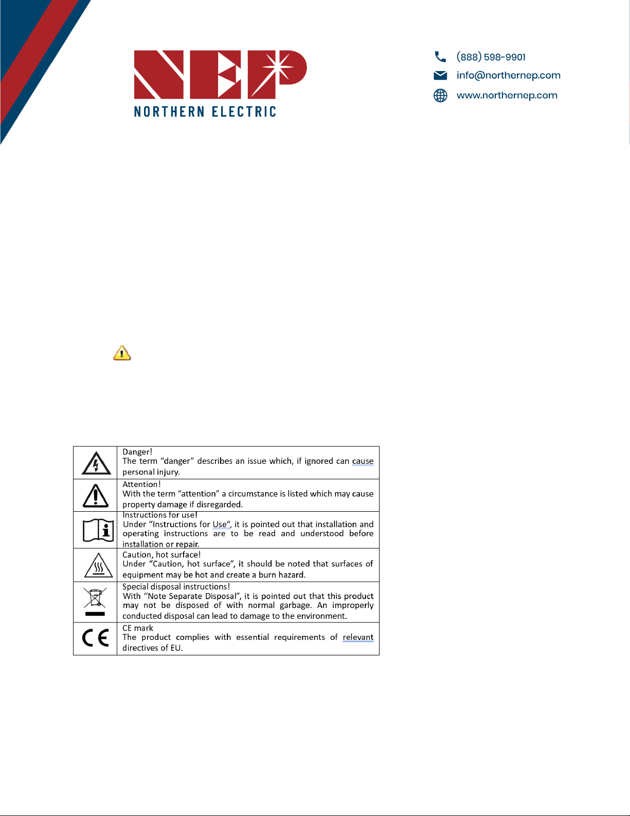
1.4 Label--------------------------------------------------------------------------------------------------------------------------------------------5
2. SAFETY INSTRUCTION------------------------------------------------------------------------------------------------------------------------------ 6
3. FCC COMPLIANCE----------------------------------------------------------------------------------------------------------------------------------- 7
4. INSTALLATION---------------------------------------------------------------------------------------------------------------------------------------- 8
4.1 NEP Parts Needed---------------------------------------------------------------------------------------------------------------------------8
4.2 Additional Parts and Tools Required----------------------------------------------------------------------------------------------------8
4.3 Lightning Surge Suppression--------------------------------------------------------------------------------------------------------------9
4.4 Installation Procedure----------------------------------------------------------------------------------------------------------------------9
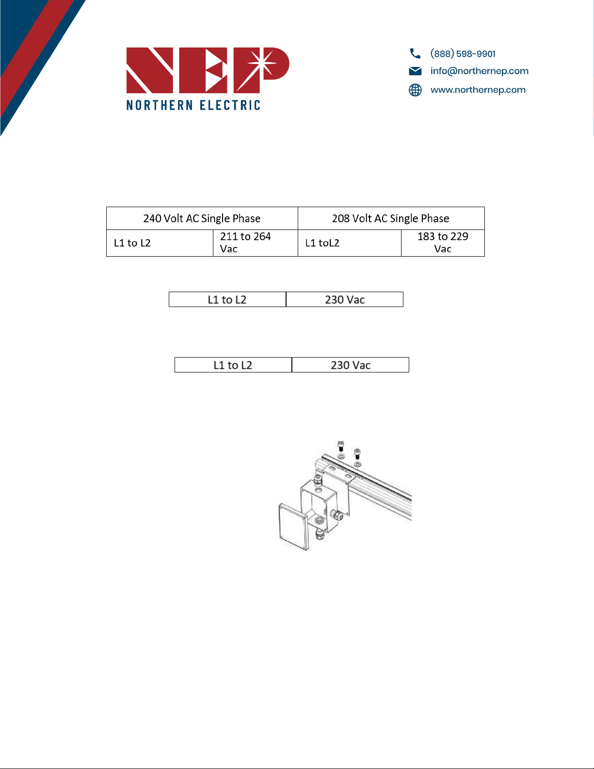
4. 5 Install the AC Branch Circuit Junction Box------------------------------------------------------------------------------------------ 10
4.6 Attach BDM-550 to the Racking--------------------------------------------------------------------------------------------------------11
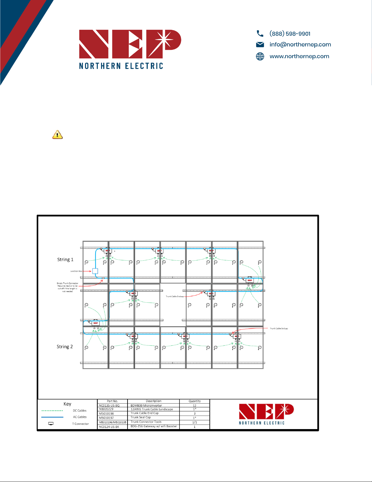
4.7 Connect the BDM-550 Trunk Cable--------------------------------------------------------------------------------------------------- 11
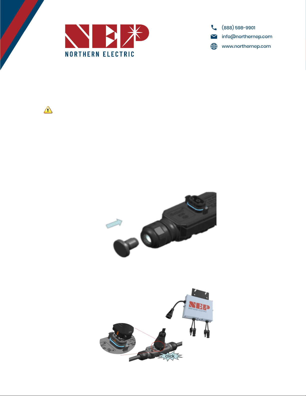
4.7.A Seal one end of trunk with an endcap-------------------------------------------------------------------------------------- 11
4.7.B Connect BDM-550 to trunk cable---------------------------------------------------------------------------------------------12
4.7.C Disconnecting BDM-550 From Trunk---------------------------------------------------------------------------------------- 12
4.7.D Homerun--------------------------------------------------------------------------------------------------------------------------- 12
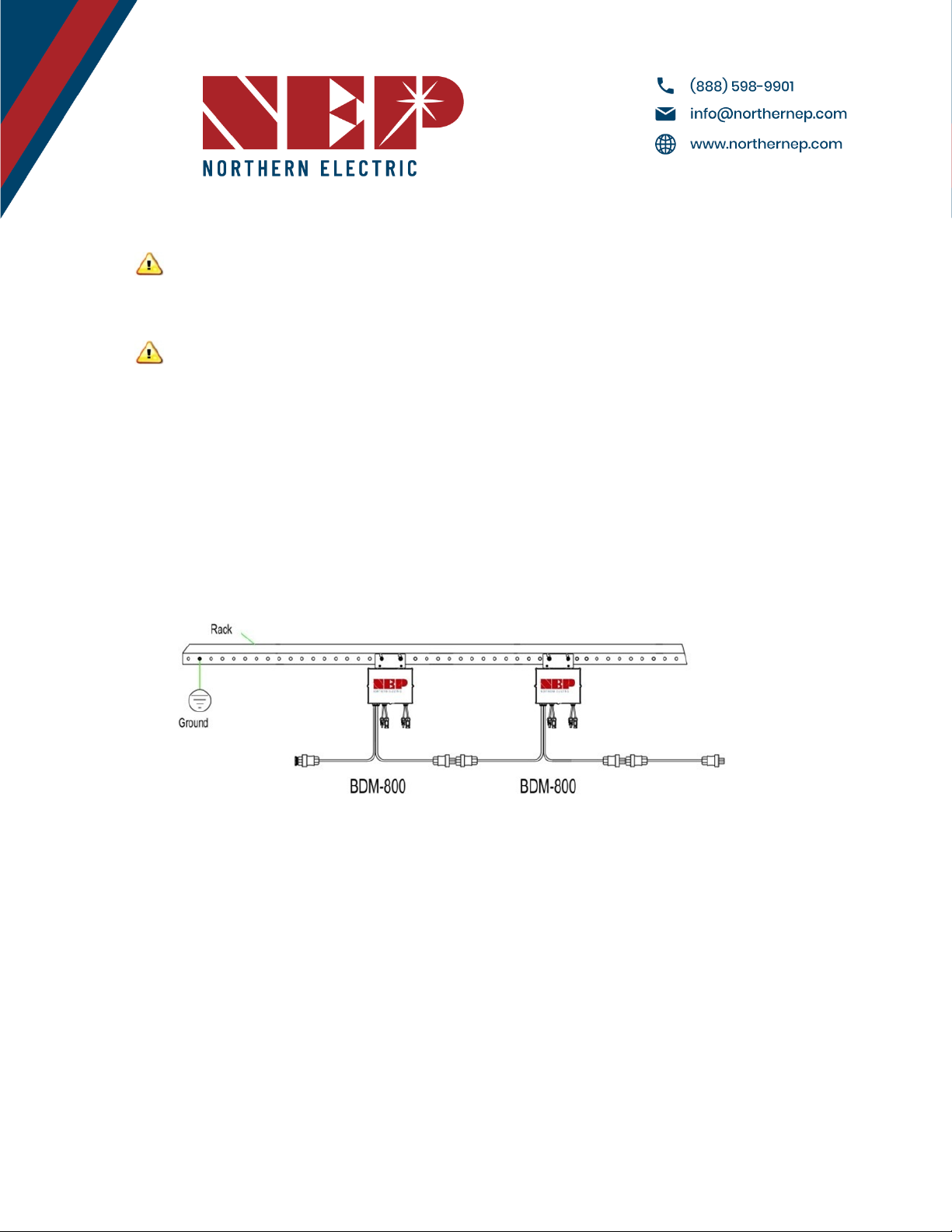
4.8 Ground the System------------------------------------------------------------------------------------------------------------------------13
4.8A Through Trunk Cable------------------------------------------------------------------------------------------------------------- 13
4.8.B Through Racking------------------------------------------------------------------------------------------------------------------ 13
5. Commissioning------------------------------------------------------------------------------------------------------------------------------------- 14
5.1 Commissioning Steps--------------------------------------------------------------------------------------------------------------------- 14
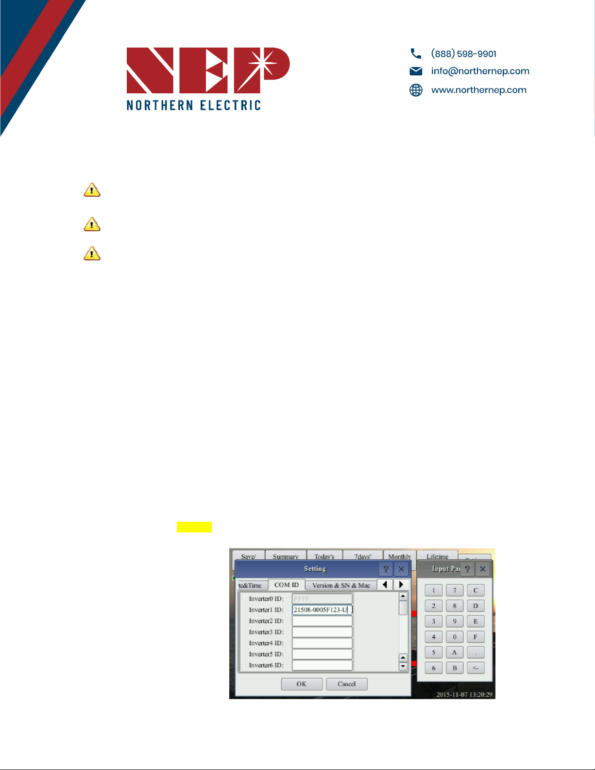
5.2 Inverter/RSD Serial Input---------------------------------------------------------------------------------------------------------------- 14
5.2.A Manually on Device--------------------------------------------------------------------------------------------------------------14
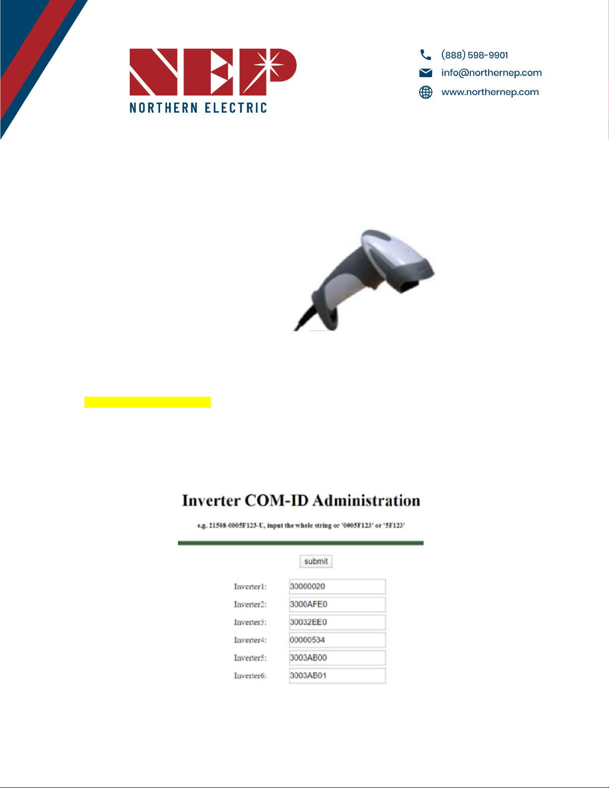
5.2.B Using USB Barcode Scanner----------------------------------------------------------------------------------------------------15
5.2.C Using Web Browser-------------------------------------------------------------------------------------------------------------- 15
5.3 Installer Registration---------------------------------------------------------------------------------------------------------------------- 16
5.4 Homeowner Registration---------------------------------------------------------------------------------------------------------------- 16
5.5 Pre-Commissioning Setup--------------------------------------------------------------------------------------------------------------- 16
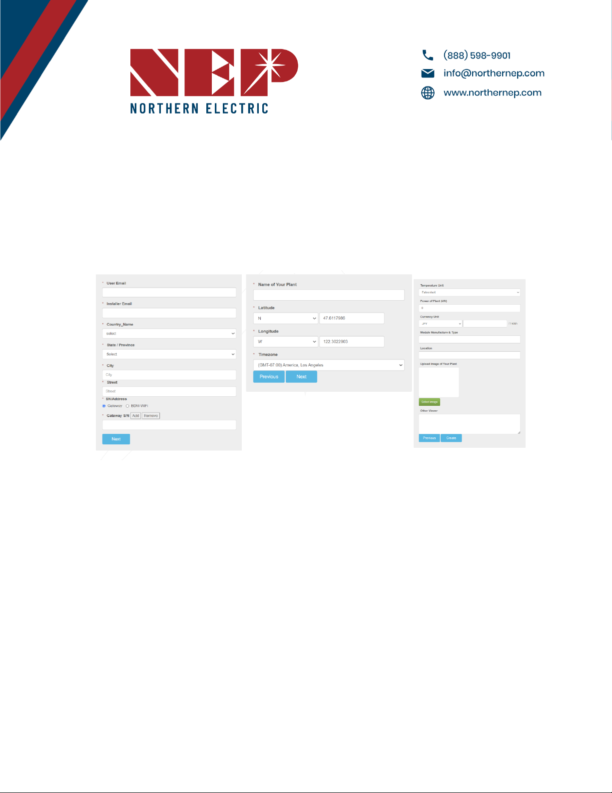
5.6 Create a Site on NEP Website-----------------------------------------------------------------------------------------------------------17
5.7 Verify and Map Site----------------------------------------------------------------------------------------------------------------------- 18
5.8 Commission the Gateway and Confirm Site Setup-------------------------------------------------------------------------------- 18
5.9 Grant Homeowner Access to Module View (Optional)---------------------------------------------------------------------------19
Modified 05/11/2023 by JMB

6. Operating Instructions----------------------------------------------------------------------------------------------------------------------------19
6.1 Status: Standby-----------------------------------------------------------------------------------------------------------------------------19
6.2 Producing Power---------------------------------------------------------------------------------------------------------------------------19
6.3 Grounding Fault---------------------------------------------------------------------------------------------------------------------------- 19
7. TROUBLESHOOTING AND MAINTENANCE--------------------------------------------------------------------------------------------------- 20
7.1 LED Indication of Error------------------------------------------------------------------------------------------------------------------- 20
7.1.C Error Mode (except for grounding error)----------------------------------------------------------------------------------- 20
7.1.B NOT communicating with BDG-256, and with no error----------------------------------------------------------------- 20
7.1.C Grounding Fault-------------------------------------------------------------------------------------------------------------------20
7.2 Troubleshooting An Inoperable BDM-550/400-------------------------------------------------------------------------------------20
7.3 Disconnecting a BDM-550 from the PV Module----------------------------------------------------------------------------------- 21
7.4 Installing a Replacement BDM-550----------------------------------------------------------------------------------------------------21
8. Data Sheets------------------------------------------------------------------------------------------------------------------------------------------22
11. WARRANTY AND PRODUCTION INFORMATION------------------------------------------------------------------------------------------ 23
What does this warranty cover and how long does it last?-------------------------------------------------------------------------- 23
What will NEP do?------------------------------------------------------------------------------------------------------------------------------23
How do you get service?----------------------------------------------------------------------------------------------------------------------23
What does this warranty not cover?-------------------------------------------------------------------------------------------------------24
Disclaimer Product----------------------------------------------------------------------------------------------------------------------------- 24
Modified 05/11/2023 by JMB

COMPANY PROFILE
Northern Electric Power Technology Inc. (NEP) is a U.S.-based company with manufacturing and
R&D facilities in Asia. Our mission is to develop cutting-edge clean energy technologies and provide
state-of-the-art solar inverter, rapid shutdown, and monitoring products to our customers.
Our headquarters are located in Tsingtao, a major industrial center and trading port in
northeastern China. Our campus occupies over 18 acres in the Tsingtao Export Processing Zone,
with more than 650,000 square feet of building space. We plan to connect our campus through a
micro smart grid demo community, powered by solar, wind, and micro turbines. In addition to our
headquarters, we have operation offices Pleasonton, USA.
Our founders are well-known experts in the fields of power electronics, automatic control, signal
processing, and communications. Each of our founders has multiple U.S. and world patents in their
specialty areas, and received Ph.D. degrees from top universities in North America. They each have
over 10 years of engineering and management experience in leading U.S. companies.
NEP offers a complete product line of grid-tied solar inverters, including micro inverters ranging
from 180W to 2000W, and industry leading Rapid Shutdown Devices (RSD). Our field deployment
results have demonstrated the high efficiency and reliability of NEP solar inverters.
At NEP, we are committed to developing Clean, Reliable, Affordable, and Efficient products for our
customers worldwide.
Modified 05/11/2023 by JMB

1. INTRODUCTION
1.1 Prefix
We hope that our products will meet your needs for renewable energy. We highly value your feedback regarding our
products and would greatly appreciate any comments you may have.
Thank you for your business, and please do not hesitate to contact us if you have any questions or concerns.
1.2 Standards Compliance
The --------------- complies with the NEC 2014 and NEC 2017 article 690.12, and CEC 2015 section 64-218.
1.3 How to Use This Manual
This manual provides detailed product information and installation instructions for the ---------------. Please read
through this manual before installation and operation.
WARNING: This indicates a situation where failure to follow instructions may be a safety hazard or cause
equipment malfunction. Use extreme caution and follow
instructions carefully.
1.4 Label
Modified 05/11/2023 by JMB

2. SAFETY INSTRUCTION
WARNING:
PLEASE READ THIS MANUAL BEFORE INSTALLATION. ANY DAMAGE TO THE PRODUCT
DUE TO NOT FOLLOWING THIS MANUAL IS NOT COVERED BY THE WARRANTEE. ALL THE INSTALLATION SHOULD BE
DONE BY CERTIFIED ELECTRICIAN.
IT IS IMPORTANT TO NOTE THAT NOTHING INSIDE THE PRODUCT SHOULD BE MODIFIED, ASIDE FROM THE CABLE
CONNECTORS. ANY MODIFICATION TO THE INTERNAL COMPONENTS OF THE PRODUCT MAY RESULT IN MALFUNCTION
OR DAMAGE, AND MAY ALSO VOID THE PRODUCT'S WARRANTY.
ALL INSTALLATION SHOULD FOLLOW THE LOCAL ELECTRIC CODES.
WARNING:
WHEN THE PHOTOVOLTAIC ARRAY IS EXPOSED TO LIGHT, IT SUPPLIES A DC VOLTAGE TO THE PVG RSD
WARNING:
THIS PHOVOLTAIC RAPIC SHUTDOWN EQUIPMENT (PVRSE) DOES NOT PERFORM ALL OF THE FUNCTIONS OF A
COMPLETE PHOTOVOLTAIC RAPIC SHUTDOWN SYSTEM (PVRSS). THIS PVRSE MUST BE INSTALLED WITH OTHER
EQUIPMENT TO FORM A COMPLETE PVRSS THAT MEETS THE REQUIREMENTS OF NEC (NFPA 70) SECTION 690.12
FOR CONTROLLED CONDUCTORS OUTSIDE THE ARRAY. OTHER EQUIPMENT INSTALLED IN OR ON THIS PV SYSTEM
MAY ADVERSLY AFFECT THE OPERATION OF THE PVRSS. IT IS THE RESPONSIBILITY OF THE INSTALLER TO ENSURE
THAT THE COMPLETED PV SYSTEM MEETS THE RAPIC SHUTDOWN FUNCTIONAL REQUIREMENTS. THIS EQUIPMENT
MUST BE INSTALLED ACCORDING TO THE MANUFACTURER’S INSTALLATION INSTRUCTIONS.
Modified 05/11/2023 by JMB

3. FCC COMPLIANCE
This equipment has been tested and found to comply with the limits for a Class B digital device, pursuant to part 15
of the FCC Rules. These limits are designed to provide reasonable protection against harmful interference in a
residential installation. This equipment generates uses and can radiate radio frequency energy and, if not installed
and used in accordance with the instructions, may cause harmful interference to radio communications. However,
there is no guarantee that interference will not occur in a particular installation. If this equipment does cause
harmful interference to radio or television reception, which can be determined by turning the equipment off and
on, the user is encouraged to try to correct the interference by one or more of the following measures:
●Reorient or relocate the receiving antenna.
●Increase the separation between the equipment and the receiver.
●Connect the equipment into an outlet on a circuit different from that to which the receiver is connected.
●Consult the dealer or an experienced radio/TV technician for help.
Changes or modifications not expressly approved by the party responsible for compliance may void the user’s authority
to operate the equipment.
Modified 05/11/2023 by JMB

4. INSTALLATION
Please be aware that the installation of this equipment carries the risk of electric shock. Conductors that are typically
grounded may become ungrounded and energized when a ground fault is detected.
4.1 NEP Parts Needed
For 12 AWG, you may have 5 units (10 Modules) per string. For 10AWG, you may have 7 Units (14
Modules) per string.
In addition to the micro inverters, PV modules, racking, and associated hardware, you’ll need the BDM-550 installation
kit. This kit includes the following items:
●AC trunk cable (one per micro)
●Protective end cap (one per branch circuit)
●Tail cable (one per branch circuit- 16’ long)
●Male connector (optional) Used to make extension cables
●BDG-256 (or BDG-256P3 for 3 phase)
The BDM-600 Ships six (6) to a box with each box measuring approximately 18” x 13.5” x 16”and weighing
57 lbs. A typical pallet contains 27 boxes.
4.2 Additional Parts and Tools Required
In addition to the PV modules, racking, and associated hardware, you’ll need the following parts:
●MLPE rail or frame attach clamps (2 per microinverter)
●AC junction boxes (multiple options possible)
●Cordgrip with locknut or strain relief fitting (one per branch circuit)
●A subpanel may be required for systems with multiple branch circuits
●Cable clips
●Sockets, wrenches, torque wrench, multimeter, small flat head screwdriver, and mirror with extension rod
●Lightning and surge suppressor (recommended)
4.3 Lightning Surge Suppression
●It's important to note that lightning strikes can cause damage to PV systems even without directly hitting the
equipment or building where the system is installed. The electrical grid can experience voltage spikes induced
by a nearby lightning strike, which can in turn damage the equipment. While the BDM-550 includes integrated
surge protection that is greater than that found in most string inverters, it is still possible for the protection to
be exceeded if the surge has sufficient energy, resulting in damage to the equipment.
●Because the NEP Limited Warranty does not cover "acts of God" such as lightning strikes, and given that these
strikes can occur anywhere, it is recommended to install surge protection as part of any solar installation. Any
surge protection devices should be installed in accordance with the vendor's instructions
4.4 Installation Procedure
Modified 05/11/2023 by JMB

WARNING: : DO NOT CONNECT BDM-550 TO THE UTILITY GRID OR ENERGIZE THE AC CIRCUIT(S) UNTIL YOU HAVE COMPLETED ALL OF
THE INSTALLATION PROCEDURES AS DESCRIBED IN THE FOLLOWING SECTIONS.
Installing the BDM-550 Micro inverter System involves several key steps:
●Measuring service and installing the AC branch circuit junction box.
WARNING: ONLY USE ELECTRICAL SYSTEM COMPONENTS APPROVED FOR WET LOCATIONS
●Attaching the BDM-550 Micro inverter to the racking.
●Connecting the BDM-550 Micro inverter daisy chain connections
●.Grounding the system (optional)1
●Completing the BDM-550 Micro inverter installation map and connecting the PV modules.
The finished system should be similar as in the diagram. Detailed installation steps are listed in the following
section.
1DC circuits of BDM-550 are isolated and insulated from ground. An integrated grounding protection circuit is included in the micro inverter.
Modified 05/11/2023 by JMB

4. 5 Install the AC Branch Circuit Junction Box
●Measure service entrance conductors to confirm AC service at the site. Acceptable ranges are
shown in the table below:
1. BDM-550-240A & BDM-550-208A (North America)
2. BDM-550-AU (Australia and New Zealand)
3. BDM-550-EU (Europe)
●Mount the adapter plate onto the PV racking system at a suitable location, usually at the end of a row of
modules.
●Install a junction box with the adapter plate that is compatible with the microinverter.
●Connect the open wire end of the AC interconnect cable to the junction box using a gland or strain relief fitting
that is appropriate for the cable. It is important to use a strain relief connector with a diameter opening of 3/8
inches for the AC interconnect cable.
Modified 05/11/2023 by JMB

4.6 Attach BDM-550 to the Racking
●Mark the approximate center points between your modules as a mark for where to mount your
microinverters.
WARNING: ALLOW A MINIMUM OF 2.75 INCHES BETWEEN THE TOP OF THE ROOF AND THE BOTTOM OF BDM-550. WE ALSO
RECOMMEND THAT YOU ALLOW .50 INCHES BETWEEN THE BACK OF THE PV MODULE AND THE TOP OF BDM-550. DO NOT MOUNT
BDM-550 IN A LOCATION THAT ALLOWS LONG-TERM EXPOSURE TO DIRECT SUNLIGHT.
●Mount one microinverter at each of these locations using the hardware recommended by the module racking
vendor. Attach the microinverter to the racking system or the adapter plate using the provided mounting
holes. Ensure that the microinverter is securely fastened and level.
4.7 Connect the BDM-550 Trunk Cable
4.7.A Seal one end of trunk with an endcap
4.7.B Connect BDM-550 to trunk cable
●Push down until you hear an audible “Click”. The Cable will be hard to remove once inserted for added
water-tightness
Modified 05/11/2023 by JMB

4.7.C Disconnecting BDM-550 From Trunk
●Using the removal tool, push the ends into the slots on the connector, slanted side down, and pull up.
4.7.D Homerun
●At the end of each string disconnect the cover for the T connector, and unscrew the wire leads.
●Pull the cable from the connector
●Attach a home run cable to end of lead, and run to combiner box.
Modified 05/11/2023 by JMB

WARNING: DO NOT EXCEED THE MAXIMUM NUMBER OF BDM-550 IN AN AC BRANCH CIRCUIT, AS DISPLAYED ON THE UNIT-RATING
LABEL (5 Units or 10 Modules). For 12AWG trunk cable, EACH BDM-550 AC BRANCH CIRCUIT MUST BE SOURCED FROM A DEDICATED
BRANCH CIRCUIT PROTECTED BY A 20A MAXIMUM BREAKER..
WARNING: MAKE SURE PROTECTIVE END CAPS HAVE BEEN INSTALLED ON ALL UNUSED AC CONNECTORS. UNUSED AC BDM-550 WIRE
HARNESS CONNECTORS ARE LIVE WHEN THE SYSTEM IS ENERGIZED BY THE UTILITY SYSTEM.
●Install a protective end cap on the open AC connector at the end of the truck cable
4.8 Ground the System
4.8A Through Trunk Cable
●Each BDM-550 has a built-in ground protection circuit. The grounding wire is connected through the trunk
cable and should be securely attached to the ground connector in the junction box to ensure proper grounding
of the microinverters. It is important to follow all local electrical codes and regulations.
4.8.B Through Racking
●BDM-550 may also be grounded through the racking as shown below.
Modified 05/11/2023 by JMB

5. Commissioning
WARNING: CONNECT BDM-550 TO THE ELECTRICAL UTILITY GRID ONLY AFTER RECEIVING PRIOR APPROVAL FROM THE UTILITY
COMPANY.
WARNING: BE AWARE THAT ONLY QUALIFIED PERSONNEL CAN CONNECT BDM-550 TO THE ELECTRICAL UTILITY GRID.
WARNING: ENSURE THAT ALL AC AND DC WIRING IS CORRECT. ENSURE THAT NONE OF THE AC AND DC WIRES IS PINCHED OR
DAMAGED. ENSURE THAT ALL JUNCTION BOXES ARE PROPERLY CLOSED.
5.1 Commissioning Steps
●Switch on the AC disconnects or circuit breakers of each BDM-550 AC branch circuit.
●Activate the main utility-grid AC circuit breaker to initiate power production. Please allow for a few minutes of
wait time.
●The BDM-550 will begin transmitting performance data through power line communication (PLC) to the
BDG-256. The duration for each BDM-550 in the system to communicate with the BDG-256 will vary depending
on the number of BDM-550s installed.
5.2 Inverter/RSD Serial Input
To ensure a successful serial input process, it is essential to have a comprehensive site map that outlines the
sequence of serial number input. It is crucial to keep in mind that the module that is connected to the longer
DC connection on the inverter will end with the number 1, while the module connected to the shorter DC
connection will end with the number 0.
5.2.A Manually on Device
●One method of inputting serial numbers is manually with the provided stylus directly into the gateway.
Although this method may be difficult for larger PV arrays, it can be a simple solution for small arrays. To input
serial numbers, navigate to Setting →COM ID on the gateway, where a list of empty cells and inverter numbers
will be displayed on the left side.
●To input serial numbers, locate the values between the dashes from the list of serials on your site map. For
example: 21508-0005F130-U. It's important to note which serial corresponds to each inverter/module number
on your site map for easier input later into the web portal. Once the serial number is inputted and saved, the
gateway will prompt a reboot.
Modified 05/11/2023 by JMB

5.2.B Using USB Barcode Scanner
●NEP offers a barcode scanner that can simplify the process of inputting serial numbers. To use the scanner, plug
it into the gateway's USB port and navigate to the COM ID screen as in section 6.1.A. Scan the barcode of the
desired module into the Inverter1 cell, and repeat until all serial numbers have been input. Make sure to note
which module corresponds to each serial number for easier identification later on. Once all serials have been
input, the gateway will prompt for a reboot.
5.2.C Using Web Browser
●Another option for serial input is through a web browser. This method requires the gateway to be assigned an
IP address and connected to WiFi. To begin, access the web browser on your device (such as a phone or laptop)
and enter the gateway's IP address followed by "/module"
(e.g. http://192.168.99.1/module)
●Once on the module input screen, you can easily input the serial numbers using your keyboard. After inputting
all the necessary serial numbers, remember to reboot the gateway to ensure the changes are applied. To do
this, simply remove the power source and plug it back in. Finally, return to the module input screen on the
gateway to confirm that all the serial numbers were successfully entered.
Modified 05/11/2023 by JMB

5.3 Installer Registration
●If you are new to using NEP products, please visit our registration page at
https://user.nepviewer.com/pv_manager/register.php?lang=en to create an account for yourself or your
company. We recommend providing as much detail as possible to help us better understand your needs.
●Once you have registered, please contact NEP Support via email at [email protected] or by calling
(888) 598-9901 to have your account upgraded to an installer account. This will allow you to access additional
features and resources to help you better manage your NEP products.
.
5.4 Homeowner Registration
●To start using NEP products, homeowners can register for an account by visiting
https://user.nepviewer.com/pv_manager/register.php?lang=en. Once they have created their account, they
can begin to enjoy the benefits of NEP's solar products.
5.5 Pre-Commissioning Setup
●Begin by connecting the BDG-256 gateway to the internet using one of the three methods outlined in the
"BDG-256 Quick Installation Guide."
●Once connected, enter the serial numbers of the inverters using one of the three methods described in the
same guide.
Note: It is recommended to complete steps 3.1 and 3.2 in a warehouse or homeowner's garage using a
standard 120V outlet before installing the gateway onto the home's 240V wiring. Only perform Step 6.4b prior
to arriving at the job site if using the NEP range extender.
Modified 05/11/2023 by JMB

5.6 Create a Site on NEP Website
●Access your installer account on the NEP website at https://user.nepviewer.com/pv_manager/login.php using
your registered email and log in to your account. Then, click on the "Add Site" button to create a new site.
●Fill out all the necessary fields in the site creator, including the serial number of the gateway, which can be
found on the top-left of the gateway bezel or by navigating to Menu > Software on the gateway. If you have
multiple gateway serial numbers, click the "Add" button above the serial number field to add more.
●Provide a name for the site and enter its accurate coordinates to receive precise weather data on the following
page
●On the last page of the site creator, provide any additional information that you deem necessary and then click
the "Create Site" button to create the site.
Modified 05/11/2023 by JMB

5.7 Verify and Map Site
●Once you have confirmed the creation of the site on the NEP website, navigate to your dashboard where you
should be able to see it.
●Click on the site to access its information and then click on "Open Viewer." The site's production data should
now be visible on the first page. Note that it may take up to two hours for the gateway and inverters to fully
register with the website.
●To access the module view, click on the dial. Here, you should see each microinverter listed. If you cannot see
them, verify that the microinverters are listed on the device's ComID menu or allow more time for them to
register.
●You can customize the site layout by navigating to Layout > Manage Layout. From here, you can drag modules
as needed and change their orientation. You can also add different zones for various roofs or sections of the
same roof from the Layout tab.
5.8 Commission the Gateway and Confirm Site Setup
●Contact NEP Support by emailing [email protected]om or calling (888) 598-9901 to schedule a
commissioning appointment for the gateway and to confirm that the site was set up correctly.
5.9 Grant Homeowner Access to Module View (Optional)
●Note that homeowners do not have access to the module view by default. If you would like to grant them
Modified 05/11/2023 by JMB

6. Operating Instructions
When DC voltage from the module is applied, the BDM-550 is powered on automatically. Once sufficient DC power is
applied, the status LED will begin to flash, indicating that the BDM-550 is live.
6.1 Status: Standby
●The LED light will turn on for 2 seconds and then turn off for 2 seconds.
●Red: Indicates an error is present.
●Orange: Indicates that the microinverter is not currently communicating with the BDG-256 but is functioning
properly.
●Green: Indicates that the microinverter is functioning properly and communicating with the BDG-256
6.2 Producing Power
●The LED light will turn on for 1 seconds and then turn off for 1 seconds.
●Orange: Indicates that the microinverter is not currently communicating with the BDG-256 but is functioning
properly.
●Green: Indicates that the microinverter is functioning properly and communicating with the BDG-256
6.3 Grounding Fault
●The LED Light is Solid Red
●The BDM-550 microinverter has multiple protective functions and will stop output power in the
event of a fault. The fault message can be transmitted to a connected BDG-256 gateway via power
line communication, and the gateway will display an error message in the form of a 16-bit error code.
Modified 05/11/2023 by JMB

7. TROUBLESHOOTING AND MAINTENANCE
WARNING: DO NOT ATTEMPT TO REPAIR THE BDM-550; IT CONTAINS NO USER- SERVICEABLE PARTS. IF TROUBLESHOOTING
METHODS FAIL, PLEASE RETURN THE BDM-550/400 TO YOUR DISTRIBUTOR FOR MAINTENANCE.
WARNING: NEVER DISCONNECT THE DC WIRE CONNECTORS UNDER LOAD. ENSURE THAT NO CURRENT IS FLOWING IN THE DC WIRES
PRIOR TO DISCONNECTING. AN OPAQUE COVERING MAY BE USED TO COVER THE MODULE PRIOR TO DISCONNECTING
WARNING: ALWAYS DISCONNECT AC POWER BEFORE DISCONNECTING PV MODULE WIRES FROM BDM-550/400. THE AC CONNECTOR
OF THE FIRST BDM-550/400 IN A BRANCH CIRCUIT IS SUITABLE AS A DISCONNECTING MEANS ONCE THE AC BRANCH CIRCUIT
BREAKER IN THE LOAD CENTER HAS BEEN OPENED.
WARNING: BDM-550/400 IS POWERED BY DC POWER FROM PV MODULES. MAKE SURE YOU DISCONNECT THE DC CONNECTIONS AND
RECONNECT DC POWER TO WATCH FOR THE TWO SECONDS LED ON AND TWO SECONDS LED OFF AFTER DC IS APPLIED.
7.1 LED Indication of Error
7.1.C Error Mode (except for grounding error)
●The LED Light Flashes Red
7.1.B NOT communicating with BDG-256, and with no error
●The LED Light Flashed Orange
7.1.C Grounding Fault
●The LED Light is Solid Red
7.2 Troubleshooting An Inoperable BDM-550/400
To troubleshoot an inoperable BDM-550/400, follow the steps in the order shown:
●Check the connection to the utility grid and verify that the utility voltage and frequency are within
the allowable ranges shown on the BDM-550/400 label.
●Verify that utility power is present at the inverter in question by removing AC and DC power, then
reconnecting the DC module connectors and watching for LED blinks. Never disconnect the DC wires
while the BDM-550/400 is producing power.
●Check the AC branch circuit interconnection harness between all BDM-550/400s and verify that each
inverter is energized by the utility grid as described in the previous step.
●MEnsure that any AC disconnects are functioning properly and are closed.
●Verify that the PV module DC voltage is within the allowable range shown on the BDM-550/400
label.
●Check the DC connections between the BDM-550 and the PV module.
●The PLC signal quality may be checked through the interface on the BDG-256 gateway. If the PLC
signal is weak, it may be due to the distance between the microinverters and the gateway.
Modified 05/11/2023 by JMB
Table of contents
Other NEP Inverter manuals