EG4 6000EX-48HV User manual
EG4 6000EX-48
INVERTER / CHARGER
User Manual
Version 1.2.0 January 2023 - Information subject to change without notice.

Table Of Contents
ABOUT THIS MANUAL ..................................................................................................................... 1
Purpose ............................................................................................................................................... 1
Scope .................................................................................................................................................. 1
SAFETY INSTRUCTIONS .................................................................................................................. 1
INTRODUCTION .............................................................................................................................. 3
Product Overview ................................................................................................................................. 4
INSTALLATION ................................................................................................................................ 5
Unpacking and Inspection ..................................................................................................................... 5
Preparation .......................................................................................................................................... 5
Mounting the Unit ................................................................................................................................. 5
Battery Connection ............................................................................................................................... 6
AC Input/Output Connection ................................................................................................................ 7
PV Connection ..................................................................................................................................... 8
Final Assembly ..................................................................................................................................... 9
Communication Connection ................................................................................................................. 10
Dry Contact Signal .............................................................................................................................. 10
OPERATION ................................................................................................................................... 11
Power ON/OFF ................................................................................................................................... 11
Operation and Display Panel ................................................................................................................. 11
LCD Display Icons ................................................................................................................................ 12
LCD Setting ......................................................................................................................................... 13
Display Setting .................................................................................................................................... 19
Operating Mode Description ................................................................................................................. 24
SPECIFICATIONS ............................................................................................................................ 2
TROUBLESHOOTING..................................................................................................................... 38
PARALLEL FUNCTION ........... ........................................................................................................ 27
BATTERY BASED COMMISSIONING GUIDE................................................................................... 36
WI-FI OPERATION GUIDE IN REMOTE PANEL .................. ........................................................... 42
BMS Communication Install................................................................................................................... 32
PARAMETER SETTING LIST .......................................................................................................... 50

1
ABOUT THIS MANUAL
Purpose
This manual describes the assembly, installation, operation and troubleshooting of this unit. Please read
this manual carefully before installation and operation. 3OHDVHNeep this manual for future reference.
Scope
This manual provides safety and installation guidelines as well as information on tools and wiring.
SAFETY INSTRUCTIONS
WARNING: This chapter contains important safety and operating instructions. Read and
keep this manual for future reference.
Before installing or using the unit, read all instructions and cautionary markings on theunit,
the batteries, and all appropriate sections of the manual.
CAUTION- Do not disassemble the unit. Take it to a qualified service center when service or
repair is required. Incorrect re-assembly may result in a risk of electric shock or fire.
To reduce risk of electric shock, shutdown and disconnect all wiring DQG SRZHU
LQSXWV RI DQ\ NLQG beforeattempting any maintenance or cleaning. Turning off the unit
alone will not reducethe risk of shock or injury.
CAUTION - Only qualified (OHFWULFDOO\WUDLQHGpersonnel can install this equipmentVDIHO\.
NEVER charge a battery below specified minimum temperature; refer to the battery data sheet.
Wire size is critical for safe operation, and optimal performance of the equipment. Refer to a
accredited sizing resource orWR cable manufacturer specifications to meet inverter/
chargerequirements.
Use caution when working with metal tools on or around all systems and batteries. Risk of
electrical arcs and/or short circuiting of equipment can lead to severe injury and damage.
Strictly follow installation procedure when connecting and disconnecting AC or DC terminals.
Refer to INSTALLATION section of the manual for details.
The iQWHUQDORYHUFXUUHQWGHYLFH is not a guarantee of battery protection. Size and install the
correct '&EUHDNHURUIXVH for the batteries if not included with the product.
GROUNDING -This inverter/charger should be connected to a permanent grounded wiring
system. The grounding system must meet the Authority Having Jurisdiction (AHJ)
requirements in your area.
NEVER short AC output and DC inputs. Do NOT connect to the grid with a shorted DC input.
Warning!! Only qualified service personQHO are able to service this device. If errors still
persist after following troubleshooting table, please contact your retailer for further
assistance.
WARNING: Because this inverter is non-isolated, only three types of PV modules are
acceptable: Monocrystalline, Polycrystalline with class A-rated, and CIGS modules. To avoid
any malfunction, do not connect any PV modules with possible current leakage to the
inverter. For example, grounded PV modules will cause current leakage to the inverter. When
using CIGS modules, please be sure NOT to groundHLWKHU39SROHV.
CAUTION: DC breakers and surge protection on PV lines DUH recommended. Without
breakers the equipment is at higher risk of damage from sources such as surges and
lighting strikesZKLFKDUHQRWXQGHUZDUUDQW\.
DISCLAIMER
EG4 reserves the right to make changes to the material herein at any time without notice. You may
refer to the EG4 website at www.eg4electronics.com for the most updated version of our manual.

2
SPECIFICATIONS
MODEL 6KW
RATED OUPUT POWER 6000W
PV INPUT
(
DC
)
Max. PV Power 7500W
Max. Input voltage
(
Maximum PV o
p
en volta
g
e
)
500 VDC
Max2XWSXW DC Power MPPT range 2 VDC~480 VDC
Workin
g
MPP ran
g
e 120 VDC~480 VDC
Max. DC Input current / 7RWDODUUD\DPSV 27A
Number of MPP TrackerV 1
GRID-TIE OPERATION,QWHUQDWLRQDO8VH2QO\
GRID OUTPUT
(
AC
)
Nominal Out
p
ut Volta
g
e 110-120VAC
(
L-N
)
/ 220-240VAC
(
L1-L2
)
Feed-in Grid Voltage Range 93.5~126.5 VAC For 110 Vac model
102~138 VAC For 120 Vac model
Feed-in Grid Fre
q
uenc
y
Ran
g
e57Hz~63Hz
Nominal Output Current 27.3A (for 110VAC)
25A
(
for 120VAC
)
Power Factor Ran
g
e >0.99
Maximum Conversion Efficienc
y
(
DC/AC
)
95%
OFF-GRID, HYBRID OPERATION
GRID INPUT
Acce
p
table In
p
ut Volta
g
e Ran
g
e 65 - 140 VAC
(
A
pp
liances
)
or 95 - 140 VAC
(
UPS
)
Fre
q
uenc
y
Ran
g
e 50 Hz/60 Hz
(
Auto sensin
g)
Ratin
g
of AC Transfer Rela
y
40A
BATTERY MODE OUTPUT
(
AC
)
Nominal Out
p
ut Volta
g
e 110-120VAC
(
L-N
)
/ 220-240VAC
(
L1-L2
)
Out
p
ut Waveform Pure Sine Wave
Efficienc
y
(
DC to AC
)
93%
BATTERY & CHARGER
Nominal DC Volta
g
e48VDC
Maximum Char
g
in
g
Current
(
from Grid
)
120A
Maximum Char
g
in
g
Current
(
from PV
)
120A
Maximum 7RWDOCharging Current 120A
GENERAL
Dimension, + X W X ' 23-3/8” x 14-3/8” x 5-1/2”
(
593.6 x 365 x 138.4 mm
)
Net Wei
g
ht lbs.( kgs)
INTERFACE
ParalleOYesUp to 9
Communication RS232/Dr
y
-Contact/Wi-Fi
ENVIRONMENT
Humidit
y
0 ~ 90% RH
(
No condensin
g)
O
p
eratin
g
Tem
p
erature 14°F to 122°F
(
-10°C to 50°C
)

3
INTRODUCTION
This is a residential self-consumption multi-function inverter, combining the functions of an inverter,
solar charge controller, and battery charger to offer uninterrupted power system in a single package. The
comprehensive LCD display offers user-configurable and easily-accessible button operations such as battery
charging current, AC or solar charging priority, and acceptable input voltage based on different applications.
Figure 1 Basic hybrid PV System Overview
Depending on different power situations, this hybrid inverter is designed to manage power from PV modules
(solar panels), battery bank, and the utility or generator AC input. When MPP input voltage of PV modules is
within acceptable range (see specification for the details), this inverter is able to charge the battery.
NOTE: Never connect the positive or negative poles of the solar equipment to ground.
NOTE: This inverter is only compatible with 240V Split-phase grid or generator input. The voltage between
Line 1 and Line 2 is equal to Line 1 to Neutral plus Line 2 to Neutral. The equipment does not support single-
phase or three-phase input or output.
6KW
L1
N
Grid
connection Load
Output
L1
N
L2 L2
L1
L2
N
L1
N
120V
L2
240V
The phase angle between L1 and L2 is 180°.
120V
120V
120V
240V
Electric
g
rids
4
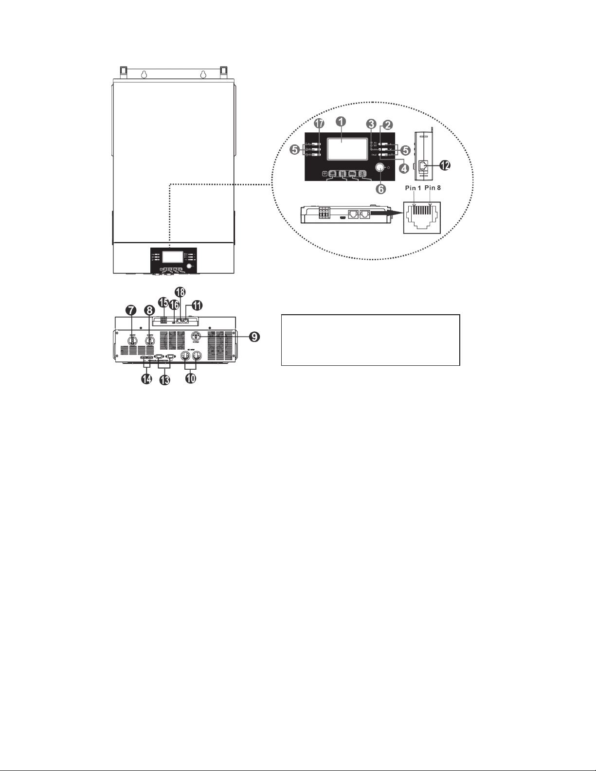
Product Overview
1. LCD display
2. Status indicator
3. Charging indicator
4. Fault indicator
5. Function buttons
6. Power on/off switch
7. AC input connectors
8. AC output connectors (Load connection)
9. PV connections
10. Battery connections
11. RS-232 communication port
12. Remote LCD panel communication port
13. Parallel communication port (only for use in parallel setups)
14. Current sharing port (only for parallel model)
15. Dry contact
16. USB communication port
17. LED indicators for USB function setting / Output source priority timer / Charger source priority setting
18. BMS communication port (RS-485)
NOTE: For parallel installation and
operation, refer to the commissioning
guide and connection diagrams.
5
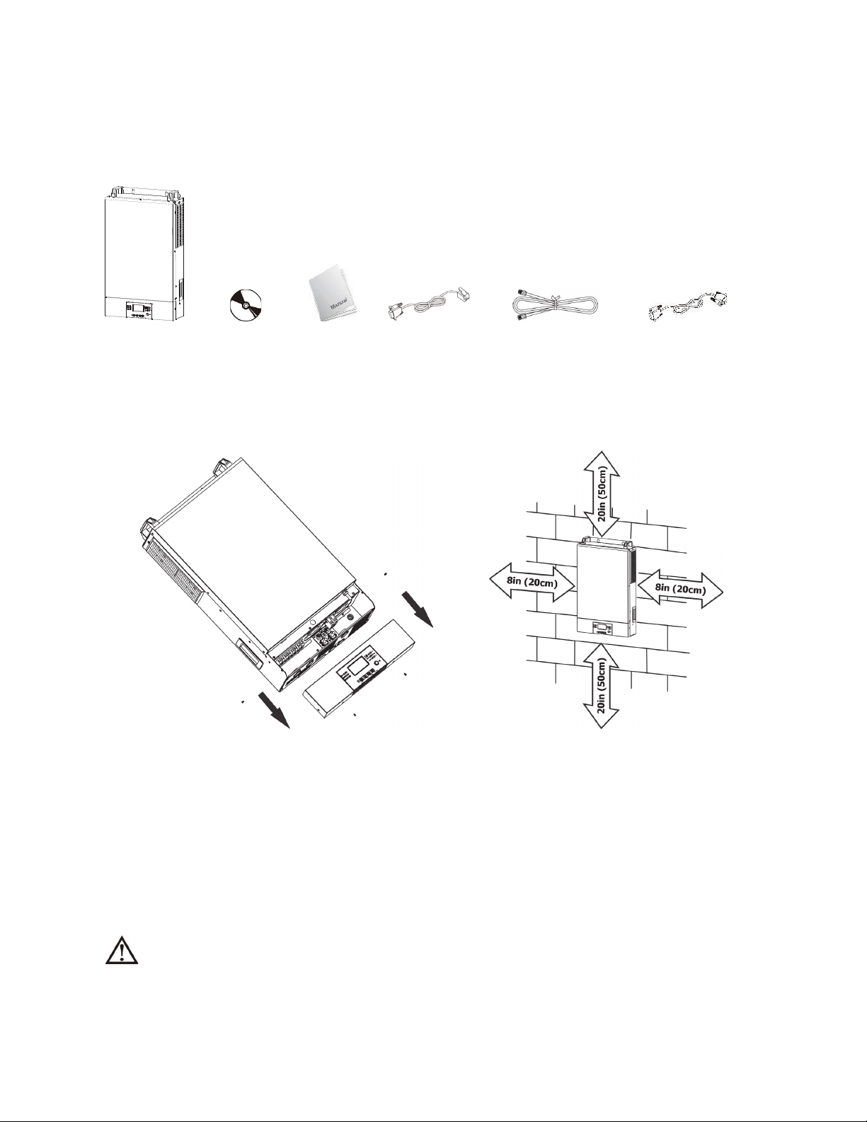
Inverter unit Software CD Manual RS-232 Cable Battery Comms Cable Parallel Cables
Preparation
To prepare for the wiring step of installation, remove the bottom cover as shown below.
Mounting the Unit
Consider the following points before selecting a location for installation:
zAvoid mounting the inverter on combustible construction materials. Masonry or fire-resistant surfaces for
mounting are recommended.
zMount on a solid surface or appropriate strut/frame.
zInstall this inverter at the operator’s eye level in order to allow the LCD display to be read at all times.
zThe ambient temperature should be between 14°F(-10°C) and 122°F(50°C) to ensure optimal operation.
zInstall the inverter vertically and follow local AHJ requirements for equipment clearances.
zEnsure enough clearance based on the diagram above for proper cooling/ventilation.
SUITABLE FOR MOUNTING ON CONCRETE OR OTHER NON-COMBUSTIBLE SURFACES ONLY.
INSTALLATION
Unpacking and Inspection
Before installation, please inspect the unit. Be sure nothing inside the package is damaged. Check to ensure the
following items are included with each inverter:

6
Battery Connection
CAUTION: For safe operation and regulation compliance, it is required to install a separate DC over-current
protector or disconnect device between battery and inverter. It may not be required to have a disconnect
device in some applications, however, you are required to have over-current protection installed. Please refer
to typical amperage in the below table for required fuse or breaker size.
WARNING! All wiring must be performed by electrically trained personnel
WARNING! It's critically important for system safety and efficient operation to
use appropriate cable sizes for battery connections. To reduce risk of injury,
please use the proper recommended cable and terminal sizes below.
Recommended battery cable and terminal size:
Model Typical
Amperage
Minimum
Battery
Capacity
Wire Size Ring Terminal Torque Value
Min size Dimensions
D (mm) L (mm)
6KW 137A 300AH 2AWG 2AWG/
38mm2
M10
13mm nut
39 ~ (2-3 Nm)
Please follow below steps to implement battery connection:
1. Assemble battery ring terminal based on
recommended battery cable and terminal size.
2. Insert the ring terminal of battery cable flatly into
battery connector of inverter and make sure the nuts
are tightened with a torque of 17-27 in-lbs/ 2-3 Nm.
Make sure polarity at both the battery and the inverter/
charger is correctly connected and ring terminals are
tightly screwed to the battery terminals.
Ring terminal:
Mounting the Inverter
Install the unit using all three screw holes. Use #8 (M4) or #10 (M5) screws.
WARNING: Shock Hazard
Installation must be performed carefully; arc and shock hazards are present.
CAUTION! Do not place anything between the flat part of the inverter terminal and the ring
terminal. Mixed materials, gaps, and loose connections can all lead to overheating.
CAUTION! Do not apply anti-oxidant substance on the terminals before terminals are connected.
CAUTION! Before connecting the DC circuit, ensure proper polarity of the system. Ensure the
positive (+) terminal of the inverter is properly connected to the battery, and disconnect/fusing or
breaker, as well as the polarity of the negative (-) connections.
AC Input/Output Connection
CAUTION! Before connecting to AC input power source, install a separate AC breaker (40A max) between
inverter and AC input power source. Ensure the input breaker and conductor ratings match. Installation of a
breaker on the AC input is required for OCP and means of disconnect. Check with your AHJ and ensure correct
system design for regulatory compliance.
CAUTION! There are two sets of terminal blocks, one for input and the other for output. While the terminals
are marked “IN” and “OUT”, double check to ensure wires throughout the system are connected and phased
correctly. Use fine stranded 90C rated wiring of the correct type based on code requirements.
WARNING! All wiring must be performed by qualified personnel. Follow the requirements of your local AHJ.
WARNING! For all AC wiring, proper sizing is required. Refer to the wire type and ampacity calculations required
by the specific design, site, and local regulatory requirements. To reduce risk of injury and damage to equipment,
please use the minimum recommended cable size as below.
Suggested minimum cable requirement for AC wiring:
Model Gauge Terminal Torque Value
6KW 10 AWG ~10-14 in-lbs (1.2-1.6 Nm)
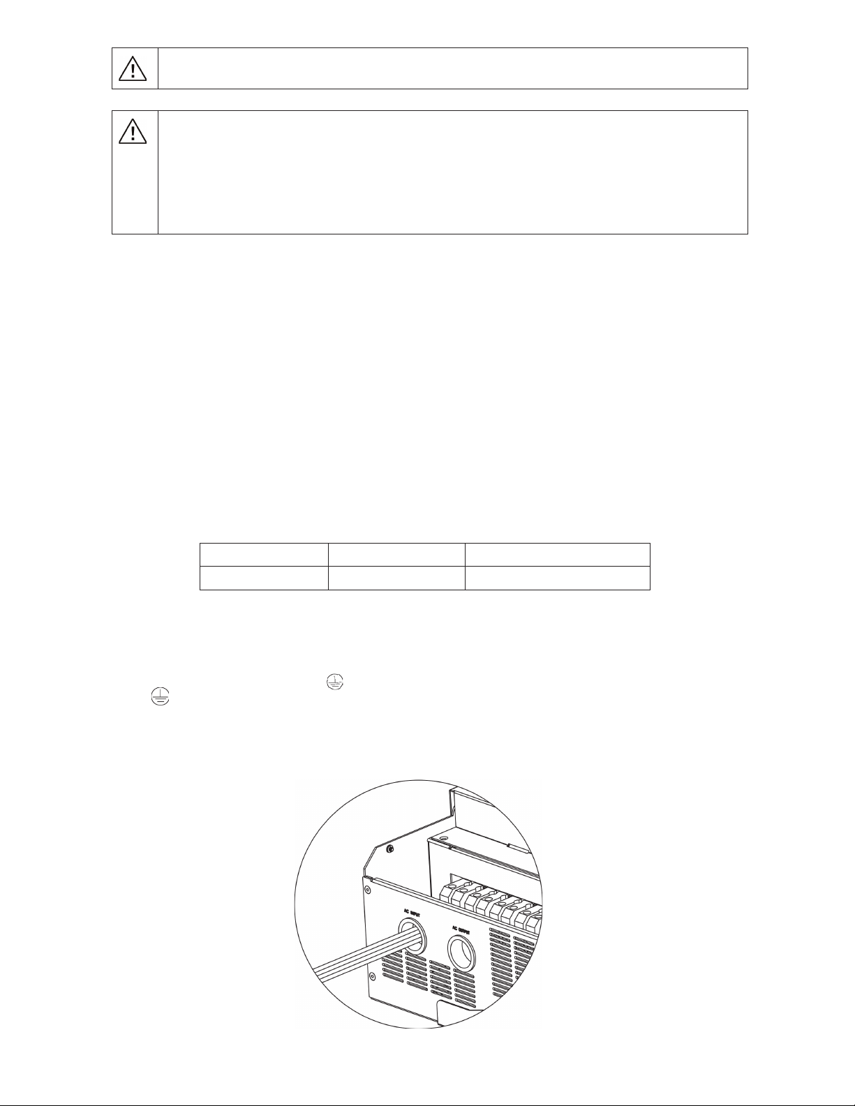
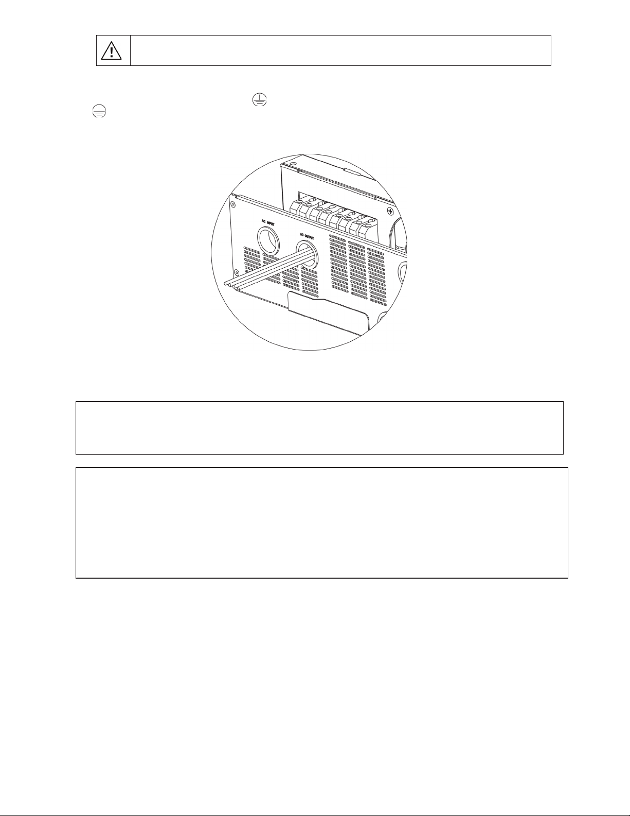
Please follow the below steps to implement AC input/output connection:
1. Before making AC input/output connection, disconnect all DC sources of energy.
2. Remove ~7/16” (10mm) of insulation from all eight wires (L1, N, L2, G).
3. Insert AC input wires according to labeling on the terminal blocks and tighten the terminal screws. Be sure to
connect the grounding conductor ( ) first.
→Ground (Green or Green with Yellow stripe)
L1 → Line (Black)
L2 → Line (Red)
N → Neutral (White or Gray)
1RWH Cord grips, conduit, or other
approved methods of securing wires must be
used.
1RWH Wire colors
may vary.
WARNING:
Ensure all AC power sources and loads are disconnected before wiring the unit.
4. Insert the AC output wires according to labeling on the terminal block and tighten terminal screws. Be sure
5. Make sure the wires are securely connected, and use required cord grips or conduit.
PV Connection
CAUTION: Before connecting to PV modules/strings, install separate DC circuit breakers or a means of
disconnect paired with properly sized fuses between inverter and PV modules/strings. DO NOT work with or
connect live PV conductors to the unit EVER. Ensure all exposed conductors are safely disconnected from the
power source.
NOTE: Use 600V/30A rated circuit breakers. DC rated breakers must be used. The over voltage category of the
PV input is II. Please Follow the steps below to complete PV connections.
WARNING! All wiring must be performed by qualified personnel.
WARNING: Making connections with live a PV source will damage the inverter!
WARNING! It's very important for system safety and efficient operation to use appropriate cables for PV
module connection. To reduce risk of injury, use the proper recommended cable size below.
CAUTION: Appliances with heavy start and run demands, such as air conditioners, require special
consideration. For many air conditioners for example, at least 2~3 minutes to restart might be required to
allow enough time to balance refrigerant gases. If a power outage occurs and recovers in a short time, it may
cause damage to the connected appliances. To prevent damage, please check with the manufacturer of the
appliance to see if it is equipped with a time-delay function or soft-start feature before installation. Overload of
the inverter/charger may trigger a fault leading to a sudden loss of AC output power, which may cause
damage to appliances with motors/compressors.
CAUTION: Important
Connect AC wire to correct terminals. If either Line 1 or 2 are reversed with Ground/Neutral it will cause a
short-circuit and damage the equipment and loads connected to the system.
to connect the grounding conductor ( ) first.
→ Ground (Green or Green with a Yellow stripe)
L1 → Line 1 (Black) 1RWH Cord grips or other approved
L2 → Line 2 (Red) methods of securing wires must be used.
N → Neutral (White or Gray)
1RWH Wire colors
may vary.

9
CAUTION: It is required to use a PV surge protection device. Damage to the inverter can occur from surges
such as lighting or short circuits.
Model Typical Amperage Cable Size Torque
6KW 27A 10AWG ~17-21 in-lbs (-2.0-2.4Nm)
PV Module Selection:
1. Open Circuit Voltage (Voc) of the PV modules/strings must not exceed the unit's maximum rating. Voc
must be calculated including the environmental impacts, such as temperature in accordance to the
module manufacturer's data sheet and reliable weather data for the installation location.
2. Voltage at Maximum Power (Vmp) of PV strings must be higher than the start-up voltage of the inverter.
WARNING: Exceeding the maximum input voltage will destroy the unit!
Solar Charging Mode
INVERTER MODEL 6KW
Max. PV Array Open Circuit Voltage 500 Vdc
PV Array MPPT Voltage Range 120-480Vdc
MPP Number 1
Follow the below steps to complete PV connection:
1. Remove 10 mm (3/8in) of insulation from positive and negative conductors.
2. Check for correct polarity of connections at the PV inputs at the disconnect,
with the disconnecting means off to ensure the exposed output in not live.
Connect the positive pole (+) of the PV source to the positive pole (+) of PV
input terminal. Connect the negative pole (-) of the PV source to the
negative pole (-) of the PV input terminal. Tighten the terminals.
Final Assembly
After connecting all wiring, please put the bottom cover back by screwing four screws as shown below.
7KLVFRYHULVFULWLFDOIRUVDIHXVHRIWKLVGHYLFHDV/(7+$/YROWDJHVRFFXUEHKLQGLW
11RWH Cord grips or Conduit must be used.
1
Communication Connection
Serial Connection
Please use the supplied communication cable to connect to inverter and PC. Insert the bundled CD into a
computer and follow the on-screen instructions to install the monitoring software. For the detailed
software operation instructions, please check the user manual of the software stored on the CD.
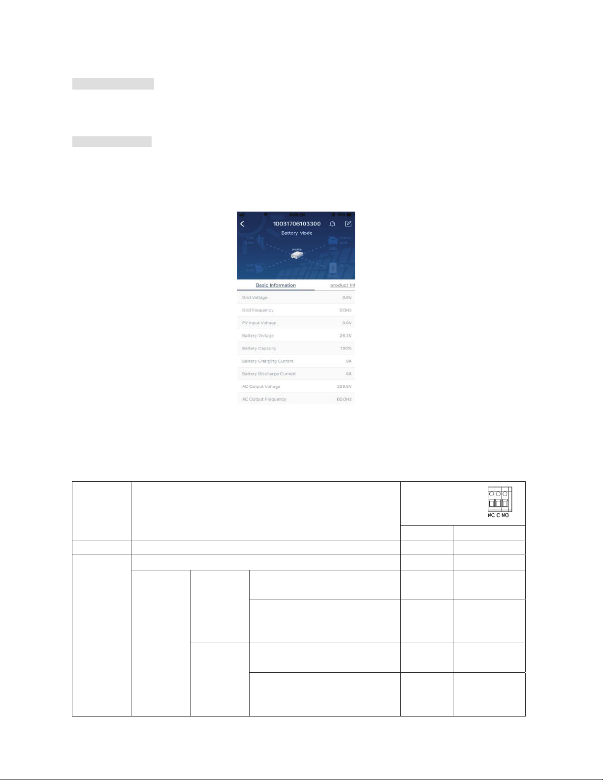
Wi-Fi Connection
Wi-Fi module can enable wireless communication between off-grid inverters and the cloud monitoring
platform. Users have complete remote monitoring and control capacity for inverters when combining the Wi-
Fi module with the SolarPower APP, available for both iOS and Android based device. All data loggers and
parameters are saved in the cloud. Refer to Appendix IV for detailed operation.
Dry Contact Signal
There is one dry contact (3A/250VAC) available on the rear panel. It could be used to deliver a signal to an
external device when battery voltage reaches a warning level.
Unit Status Condition Dry contact port:
NC & C NO & C
Power Off Unit is off and no output is powered. Close Open
Power On
Output is powered from Utility. Close Open
Output is
powered
from
Battery or
Solar.
Program 01
set as SUB
Battery voltage < Low DC warning
voltage Open Close
Battery voltage > Setting value in
Program 21 or battery charging
reaches floating stage
Close Open
Program 01
is set as
SBU
Battery voltage < Setting value in
Program 20 Open Close
Battery voltage > Setting value in
Program 21 or battery charging
reaches floating stage
Close Open
1
OPERATION
Power ON/OFF
After completing installation of the unit, the next step is powering on for setup. Start by pressing the
On/Off switch (located on display unit) to power on the system.
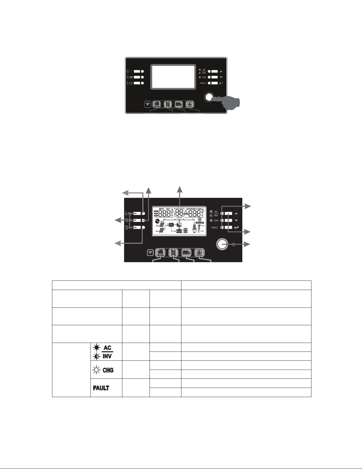
Operation and Display Panel
Refer to the diagram and table below for details on the operation and display panel. There are three
indicators, four function keys, and an LCD display.
LCD display
LED Indicators
LED Indicator Messages
Setting LED1 Green Solid On Reserved for future features
Setting LED2 Green Solid On Reserved for future features
Setting LED3 Green Solid On Reserved for future features
Status
Indicator
Green Solid On Output is powered by utility in Line mode.
Flashing Output is powered by battery or PV in battery mode.
Green Solid On Battery is fully charged
Flashing Battery is charging.
Red Solid On Fault mode
Flashing Warning mode
Status
indicators
Function keys
On/off switch
Function keys
Setting LED 3
Setting LED 1
Setting LED 2

1
Function Keys
Function Key Description
ESC Exit the setting/go back
Reserved Reserved
Reserved Reserved
Up Scroll to previous selection
Down Scroll to next selection
Enter To confirm/enter the selection in setting mode
LCD Display Icons
Icon Function
Input source information
Indicates AC input information is being displayed
Indicates PV1 input information is being displayed (PV2 not used)
Left digital display information
Indicates input voltage, input frequency, battery voltage, PV
voltage, charger current
Middle digital display information
Indicates the setting when cycling through options.
Indicates the warning and fault codes.
Warning: Flashing with warning code
Fault: display with fault code
Right digital display information
Displays the output voltage, output frequency, load percent, load VA, load
W, PV charger power, DC discharging current based on current unit being
displayed and cycled through.
Battery information
Displays battery state of charge (SOC) by ranges from 0-24%, 25-49%,
50-74%, and 75-100% per bar, and charging status.

1
Load information
Indicates output overload.
Indicates the load level by 0-24%, 25-49%, 50-74%, and 75-100%.
0%~24% 25%~49% 50%~74% 75%~100%
Mode operation information
Indicates connection to an AC input source.
Indicates connection of the PV array.
Indicates solar is being used to charge the battery bank.
Indicates the DC/AC inversion is working.
Mute operation
Alarm is disabled. Warning: Will not signal a fault when disabled!
LCD Setting
After pressing and holding ENTER button for 3 seconds, the unit will enter setting mode. Press “UP” or “DOWN”
buttons to select setting programs. Then, press the “ENTER” button to confirm the selection or the ESC
button to exit.
Program Description Selectable option
00 Exit setting menu
Escape
01 Output source priority selection
SUB (Default) Solar energy provides power to the
loads as first priority.
If solar energy is not sufficient to
power all connected loads, Utility
energy will supply power to the loads
at the same time.
SBU Solar energy provides power to the
loads as first priority.
If solar energy is not sufficient to
power all connected loads, battery
energy will supply power to the loads
at the same time.
Utility provides power to the loads
only when battery voltage drops to
either low-level warning voltage or
the setting point in program 20, or if
solar and battery is not sufficient.

1
02 AC input voltage range
Appliances
(Default setting)
If selected, acceptable AC input
voltage range will be set to
65-140VAC.
UPS If selected, acceptable AC input
voltage range will be set to
95-140VAC.
03 Output voltage
110Vac 120V (Default setting)
04 Output frequency
50Hz 60Hz (Default setting)
05 Solar supply priority
Available power will
charge battery first
(default setting)
Solar energy provides power to
charge battery as first priority.
Power supplies the
loads first
Solar energy provides power to the
loads as first priority.
06
Overload bypass:
When enabled, the unit will
transfer to line mode if
overload occurs in battery
mode.
Bypass disabled Bypass enable (default setting)
07 Auto restart when overload
occurs
Restart disable
(default setting)
Restart enabled
08 Auto restart when over
temperature occurs
Restart disable
(default setting)
Restart enabled
09
Solar energy feed to grid
configuration
WARNING: THIS SETTING
IS NOT &(57,),(')25
7+(81,7('67$7(6
$/:$<6*(763(&,),&
3(50,66,21)520
<28587,/,7<$1'$+-
7223(5$7(7+,602'(
Feed to grid disable
(default setting)
Solar energy back-feed to grid
disable.
Feed to grid enable Solar energy back-feed to grid
enable.

1
10
Charger source priority:
Configure battery charger
source priority
If this inverter/charger is working in Line, Standby or Fault
mode, charger source can be programmed as below:
Solar first Solar energy will charge battery as
first priority.
Utility/AC input will charge battery
only when solar energy is not
available.
Solar and Utility
(default)
Solar energy and utility/AC input will
charge battery at the same time.
Solar only Solar energy will be the only charger
source, even when utility/AC input
power is available.
If this inverter/charger is working in Battery mode, only
solar energy can charge the battery. Solar energy will
charge battery if it's available and sufficient.
11
Maximum charging current:
To configure total charging
current for solar and utility
chargers.
(Max charging current =
utility/AC input charging
current + solar charging
current)
60A (default setting) The setting range is from 10A to
120A. Each click is a 10A increment.
13 Maximum utility/AC input
charging current
30A (default setting) The setting range is from 10A to
120A. Each click is a 10A increment.
14 Battery type
AGM (default) Flooded
User-Defined If “User-Defined” is selected, battery
charge voltage and low DC cut-off
voltage can be set up in program 17,
18 and 19.
EG4 If this is selected, programs 11,
17, 18 and 19 will be automatically
set up. Please contact the battery
supplier for installation procedure.
$LVQHHGHGIRU
N:39FDSDFLW\

1
LIb-protocol Select “ LIb” if using Lithium battery
compatible to Lib protocol. If
selected, programs of 11, 17, 18 and
19 will be automatically set up. No
need for further setting.
3rd party Lithium
battery
If selected, programs of 11, 17, 18
and 19 will be automatically set up.
Please contact the battery supplier
for installation procedure.
17 Bulk charging voltage
(C.V voltage)
Default setting: 56.4V
If self-defined is selected in program 14, this program can
be set up. Setting range is from 48.0V to 64.0V. Each click is
an increment of 0.1V.
18 Float charge voltage
Default setting: 54.0V
If self-defined is selected in program 14, this program can
be set up. Setting range is from 48.0V to 64.0V. Each click is
an increment of 0.1V.
19 Low DC cut off battery voltage
setting
Default setting: 40.8V
If self-defined is selected in program 14, this program can be
set up. Setting range is from 40.8V to 48.0V. Each click is an
increment of 0.1V. Low DC cut-off voltage will be fixed to
setting value no matter what percentage of load is
connected.
20 Bypass loads to grid when
grid is present.
default setting: 46V
Setting range is from 44V to 51V
and each click is an increment of
1V.
In EG4 Mode you will see a
percentage instead
21 Set point for transfer back to
off-grid operation if system is
bypassed based on 20
Battery fully charged The setting range is from 48V to
58V, Each click is an increment of
1V.
In EG4 Mode you will see a
percentage instead
Default setting: 54V
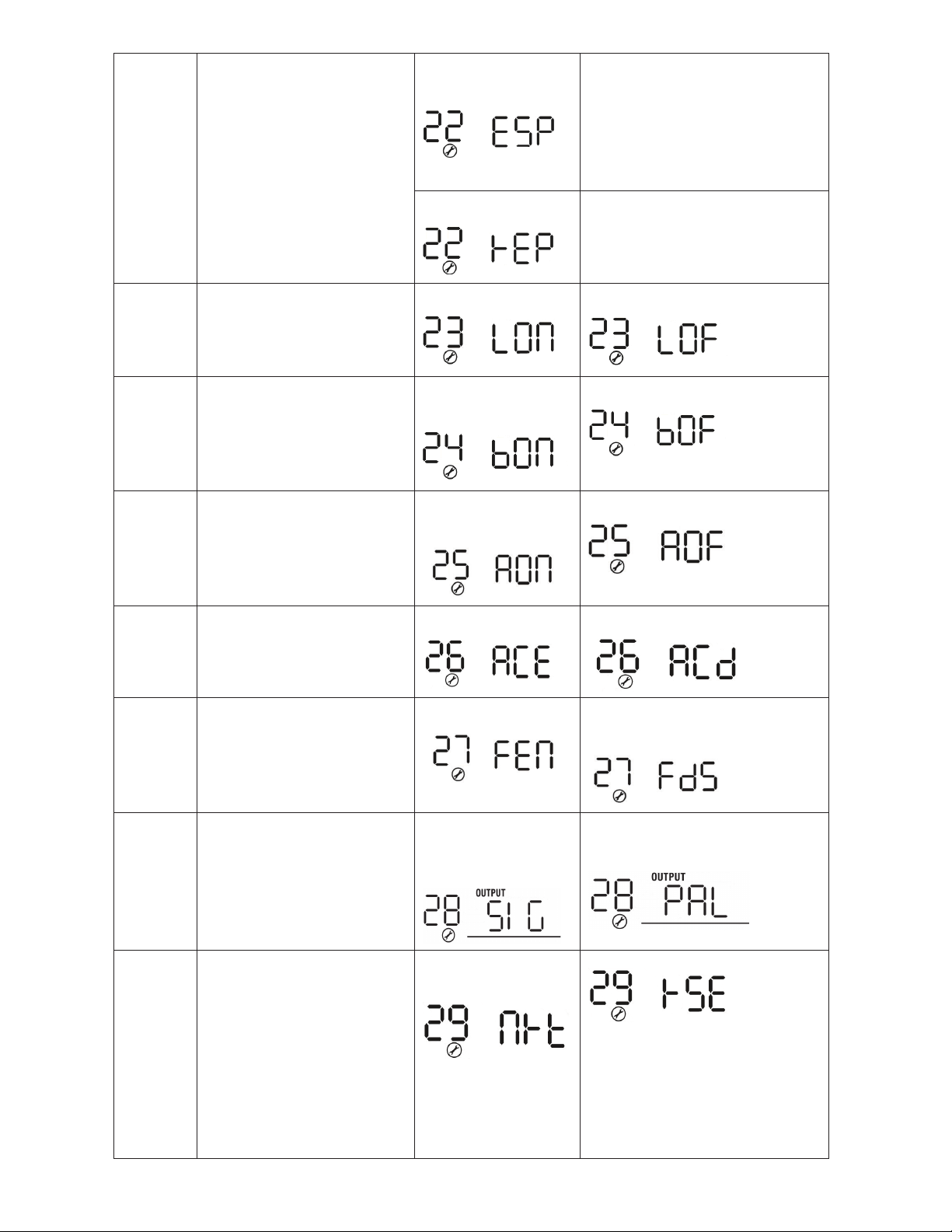
22 Auto return to default display
screen
Return to default
display screen (default)
If selected, no matter how users
switch display screen, it will
automatically return to default
display screen (Input voltage
/output voltage) after no button is
pressed for 1 minute.
Stay at latest screen If selected, the display screen will
stay at latest screen user selects
(good for keeping your favorite
view up)
23 Backlight control
Backlight on (default) Backlight off
24 Alarm control
Alarm on (default
setting)
Alarm off
25 Beeps while primary power
source is interrupted/faults
Alarm on (default
setting)
Alarm off
26 AC coupling (may require
firmware update not available
at release date of this model)
Enable Disable
27
Record Fault codes
(this is best to
enable)
Record enabled (default) Record disable
28
AC output mode
*This setting is only available
when the inverter is in standby
mode (Switch off).
Single: When selected,
the unit is used in
standalone operation.
Parallel: When selected, Parallel
stacking of up to 9 units is enabled
29 Reset PV energy storage kwh
history
Not reset (default
setting)
Reset
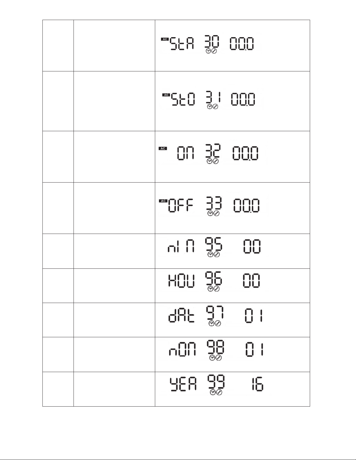
30 Scheduled Start charging
time for AC charger
00:00 (default setting)
The setting range of starting time for the AC charger is from
00:00 to 23:00, each click is 1 hour.
31 Scheduled Stop charging
time for AC charger
00:00 (default setting)
The setting range of stop charging time for AC charger is
from 00:00 to 23:00, each click is 1 hour.
32 Scheduled time for AC output
on
00:00 (default setting)
The setting range of scheduled time for AC output on is from
00:00 to 23:00, each click is 1 hour.
33 Scheduled time for AC output
off
00:00 (default setting)
The setting range of scheduled time for AC output off is from
00:00 to 23:00, each click is 1 hour.
95 Current time setting – Minute
For minute setting, the range is from 00 to 59.
96 Current time setting – Hour
For hour setting, the range is from 00 to 23.
97 Current time setting– Day
For day setting, the range is from 00 to 31.
98 Current time setting– Month
For month setting, the range is from 01 to 12.
99 Current time setting – Year
For year setting, the range is from 16 to 99.
This manual suits for next models
1
Table of contents
Other EG4 Inverter manuals


Popular Inverter manuals by other brands


Mitsubishi Electric
Mitsubishi Electric FR-F820-00046 instruction manual

Viessmann
Viessmann Vitosol-F XL manual

MMD Equipment
MMD Equipment IGR2000P user manual

Flexsolar
Flexsolar C120 Instruction manual & warranty information

FujiFilm
FujiFilm FRENIC-Mini instruction manual

Bryant
Bryant ASPAS1BBL025 owner's manual