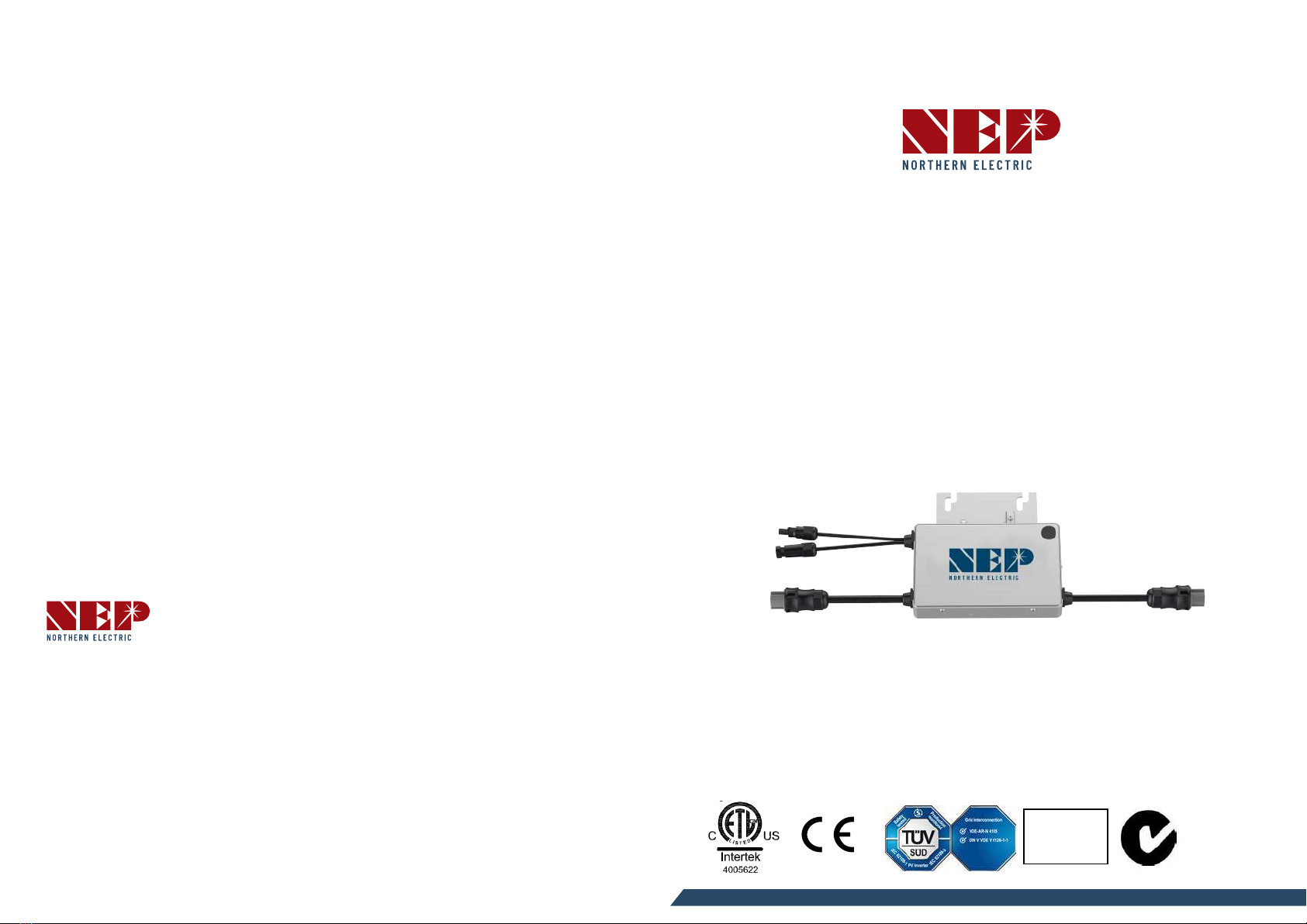
NEP BDM-250-240A User manual
USA
Address: 1781 Riverview Ave., Tracy, CA 95377
Australia
Address: 9 Meander Grove, Cameron Park, NSW2285
China
Address: No.1 Anhe Rd Tsingtao Export Processing Zone, Tsingtao, China 266113
TEL: +86 532 87963900
FAX: +86 532 81100917
SAA
122309
N
136
BDM-250-240A
BDM-250-AU
BDM-250-LV
BDM-250-208A
BDM-250-EU
Installan and Operan Manual

COMPANY PROFILE
1. INTRODUCTION
1.1 Prex
1.2 Grid-ed PV System
1.3 How to Use This Manual
1.4 Label
2. SAFETY INSTRUCTION
3. FCC COMPLIANCE
4. INSTALLATION
Parts Included
Other Parts and Tools Required
Lightning Surge Suppression
Installaon Procedure
Step 1 - Install the AC Branch Circuit Juncon Box
Step 2 - Aach the BDM-250 to the Racking
Step 3 - Connect the BDM-250 Wiring Harnesses
Step 4 – Ground the System
Step 5 – Complete the connecon map and
connect the PV Modules
5. COMMISSIONING
6. OPERATING INSTRUCTIONS
7. TROUBLRSHOOTING MAINTENANCE
8. SPECIFICATION
9. WARRANTY AND PRODUCTION INFORMATION
WARRANTY CARD
01
02
02
02
02
02
03
03
04
04
04
04
04
05
06
07
08
09
10
11
12
14
16
CONTENTS

COMPANY PROFILE
Northern Electric & Power Inc. (NEP) was founded in the United States and has
manufacturing and R&D facilies in China. The mission of the company is to
develop cung-edge clean energy technologies and provide state-of-the-art solar
inverter products to its customers. The rst round of investment to the company
was US$20 Million, with a planned total investment of US$50 Million. The
company is headquartered in the city of Tsingtao, a major industrial center and
trading port in the northeastern China. The company campus occupies more than
18 acres in the Tsingtao Export Processing Zone, and has more than 650,000
square feet building space. The campus is planned to be connected through a
micro smart grid demo community and powered by electricity from solar, wind
and micro turbines. Outside China, the company has operaon oces in Chicago,
U.S. and Vancouver, Canada.
The technology founders of the company are well-known experts in the elds of
power electronics, automac control, signal processing, and communicaons.
Each of the founders has mulple U.S. and world patents in their specialty areas.
They received Ph.D. degrees from top universies in North America, and each has
more than 10 years engineering and management experiences in leading U.S.
companies.
NEP has a complete product line of grid-ed solar inverters, including
250W~500W micro inverters, 1.5kW~5kW single phase solar inverters, and
10kW~500kW three-phase solar inverters. Field deployment results demonstrated
high system eciency and reliability of NEP solar inverters.
NEP is commied to develop Clean, Reliable, Affordable and Efficient (CARE)
products for worldwide customers.
0 1
1. INTRODUCTION
1.1 Prex
Dear customer, thank you for choosing the BDM-250 micro inverter from NEP.
We hope you will nd our products meet your need for renewable energy.
Meanme, we appreciate your feedback regarding our products.
1.2 Grid-ed PV System
Grid-ed PV system consists of PV panels, grid-ed inverter and juncon boxes.
The DC output from the PV panels is converted into AC energy and feedback to
the grid through the BDM-250. BDM-250 series PV micro inverter contains
isolaon transformer with basic insulaon between PV input and AC grid output.
The PV panel terminals on BDM-250 shall not be earthed via external wiring, for
BDM-250 connects PV panel to earth via an internal earth fault interrupng 1A
fuse.
1.3 Hw tUse This Manual
This manual provides detailed product informaon and installaon instrucons
for the BDM-250 micro solar inverter. Please read through this manual before
installaon and operaon.
WARNING: This indicates a situaon where failure to follow instrucons
may be a safety hazard or cause equipment malfuncon. Use extreme
cauon and follow instrucons carefully.
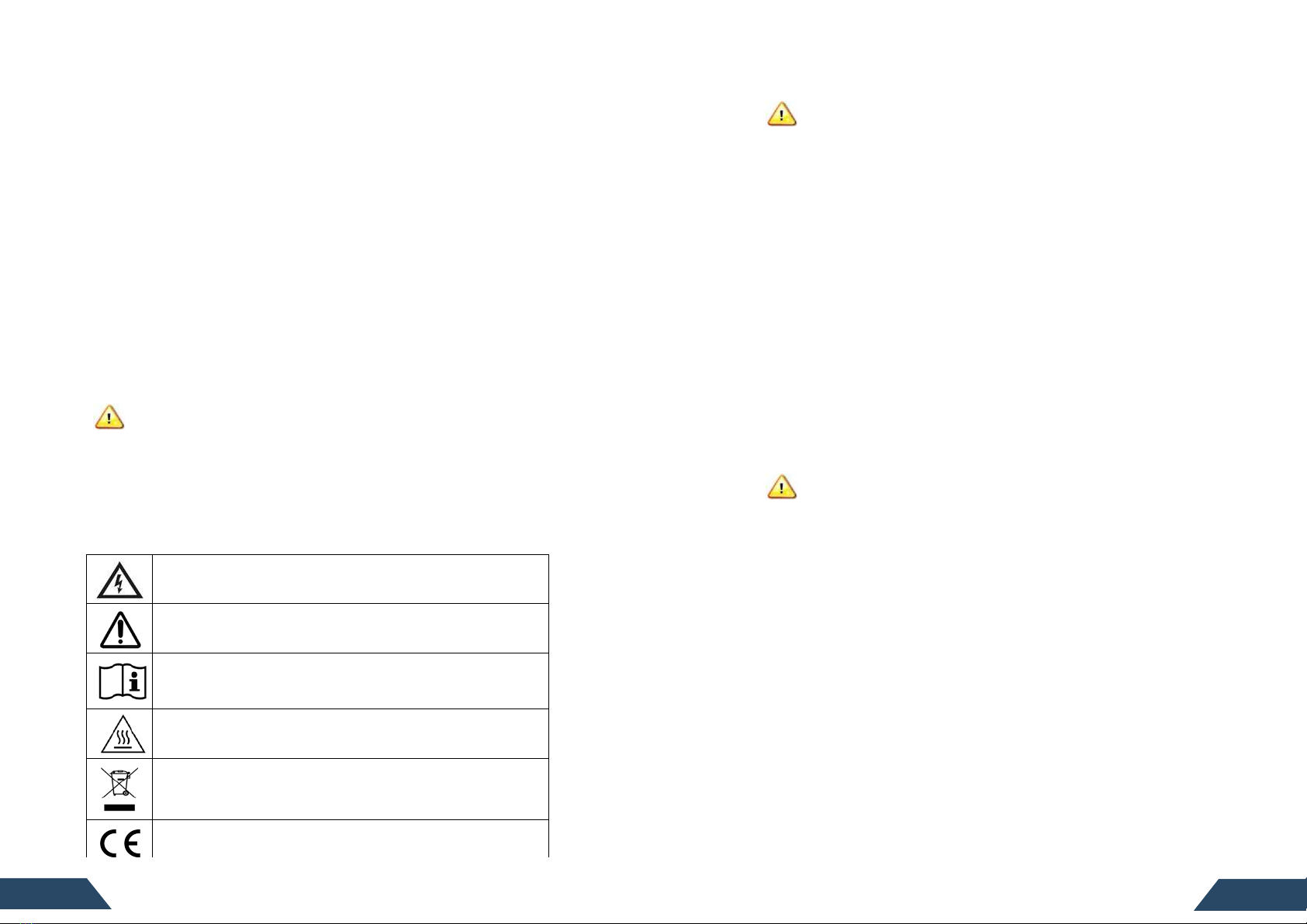
1.4 Label
The label is located on the side of the inverter. The informaon on the label
includes technical data as well as type, rmware version and serial number of the
device. Safety instrucons on the label are listed and explained below:
Danger!
The term “danger” describes an issue which, if ignored can cause
personal injury.
Aenon!
With the term “aenon” a circumstance is listed which may
cause property damage if disregarded.
Instrucons for use!
Under “Instrucons for Use“, it is pointed out that installaon and
operang instrucons are to be read and understood before
installaon or repair.
Cauon, hot surface!
Under “Cauon, hot surface”, it should be noted that surfaces of
equipment may be hot and create a burn hazard.
Special disposal instrucons!
With “Note Separate Disposal”, it is pointed out that this product
may not be disposed of with normal garbage. An improperly
conducted disposal can lead to damage to the environment.
CE mark
The product complies with essenal requirements of relevant
direcves of EU
2. SAFETY INSTRUCTION
WARNING:
PLEASE READ THIS MANUAL BEFORE INSTALLATION. ANY DAMAGE TO THE PRODUCT DUE TO NOT
FOLLOWING THIS MANUAL IS NOT COVERED BY THE WARRANTEE.
ALL THE INSTALLATION SHOULD BE DONE BY CERTIFIED ELECTRICIAN.
BESIDES THE CABLE CONNECTORS, NOTHING INSIDE THE INVERTER SHOULD BE MODIFIED.
ALL INSTALLATION SHOULD FOLLOW THE LOCAL ELECTRIC CODES. FURTHER PROTECTION ON THE
AC WIRING FROM THE INVERTERS SHOULD BE PROVIDED AND MAY BE REQUIRED BY LOCAL AND
NATIONAL WIRING REGULATIONS. THIS PROTECTION IS LIKELY TO INCLUDE RESIDUAL CURRENT
DEVICES, EARTH FAULT MONITORS AND CIRCUIT BREAKERS. THIS PRODUCT MAY CAUSE AC
CURRENT WITH A DC COMPONENT. IF A RESIDUAL CURRENT-OPERATED PROTECTIVE DEVICE
(RCD) OR A MONITORING DEVICE (RCM) IS USED FOR PROTECTION IN CASE OF DIRECT OR
INDIRECT CONTACT, ONLY AN RCD OR RCM OF TYPE B IS ALLOWED ON THE AC SIDE OF THIS
PRODUCT.
NEVER DISCONNECT PV MODULE FROM THE MICRO-INVERTER WITHOUT FIRST ISOLATING THE AC
MAINS. ALL PV CONNECTORS AND AC CONNECTORS ARE FORBIDDEN TO BE DISCONNECTED
UNDER LOAD BEFORE SWITCHING OFF THE CIRCUIT BREAKER ON THE AC BRANCH.
PLEASE CONTACT AUTHORIZED SERVICE AGENTS FOR ANY SERVICE WORK.
BDM-250 IS A GRID-TIED SOLAR INVERTER. IT MAY REQUIRE APPROVAL FROM LOCAL UTILITY
COMPANY TO CONNECT IT TO THE POWER GRID.
BDM-250 DOES NOT INCLUDE COMPONENTS THAT CAN BE SERVED BY CUSTOMERS.
WARNING:
WHEN THE PHOTOVOLTAIC ARRAY IS EXPOSED TO LIGHT, IT SUPPLIES A DC
VOLTAGE TO THE MICRO-INVERTER.
3. FCC COMPLIANCE
This equipment has been tested and found to comply with the limits for a Class B
digital device, pursuant to part 15 of the FCC Rules. These limits are designed to
provide reasonable protecon against harmful interference in a residenal
installaon. This equipment generates uses and can radiate radio frequency
energy and, if not installed and used in accordance with the instrucons, may
cause harmful interference to radio communicaons. However, there is no
guarantee that interference will not occur in a parcular installaon. If this
equipment does cause harmful interference to radio or television recepon,
which can be determined by turning the equipment oand on, the user is
encouraged to try to correct the interference by one or more of the following
measures:
●Reorient or relocate the receiving antenna.
●Increase the separaon between the equipment and the receiver.
●Connect the equipment into an outlet on a circuit dierent from that to
which the receiver is connected.
●Consult the dealer or an experienced radio/TV technician for help.
Changes or modicaons not expressly approved by the party responsible for
compliance may void the user’s authority to operate the equipment.
03
0 2
03
4. INSTALLATION
WARNING: BE AWARE THAT INSTALLATION OF THIS EQUIPMENT INCLUDES RISK OF
ELECTRIC SHOCK. NORMALLY GROUNDED CONDUCTORS MAY BE UNGROUNDED AND
ENERGIZED WHEN A GROUND FAULT IS INDICATED.
Parts Included
In addion to the micro inverters, PV modules, racking, and associated hardware,
you’ll need the BDM-250 installaon kit. This kit includes the following items:
●Protece end cap
●Mounng Bracket (adapter plate)
●AC interconnect cable and protece end CAP
Other Parts and Tls Required
In addion to your PV array and its associated hardware, you will need the
following parts:
●Juncon box
●Connuous grounding conductor,grounding washers
●Number 2 Phillips screwdriver
●Sockets, wrenches for mounng hardware
●Torque wrench
●Mounng hardware suitable for module racking
Lightning Surge Suppressin
Lightning does not actually need to strike the equipment or building where PV
system is installed to cause damage. Oen, a strike nearby will induce voltage
spikes in the electrical grid that can damage equipment. BDM-250 has integrated
surge protecon, greater than most string inverters. However, if the surge has
sucient energy, the protecon built into the BDM-250 can be exceeded, and
the equipment can be damaged.
Since the NEP Limited Warranty does not cover “acts of God” such as lightning
strikes, and since lightning strikes can occur anywhere, it is best pracce to install
surge protecon as part of any solar installaon. Installaon of surge protecon
devices should follow vendor instrucons.
Installan Prcedure
WARNING: DO NOT CONNECT BDM-250 TO THE UTILITY GRID OR ENERGIZE THE AC
CIRCUIT(S) UNTIL YOU HAVE COMPLETED ALL OF THE INSTALLATION PROCEDURES AS
DESCRIBED IN THE FOLLOWING SECTIONS.
Installing the BDM-250 Micro inverter System involves several key steps:
1. Measuring service and installing the AC branch circuit juncon box.
WARNING: ONLY USE ELECTRICAL SYSTEM COMPONENTS APPROVED FOR WET
LOCATIONS.
2. Aaching the BDM-250 Micro inverter to the racking.
3. Connecng the BDM-250 Micro inverter wiring harnesses.
4. Grounding the system.
5. Compleng the BDM-250 Micro inverter installaon map and connecng the
PV modules.
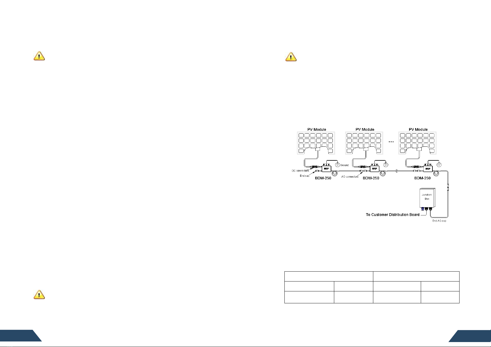
The nished system should be similar as in the diagram. Detailed installaon
steps are listed in the following secon.
Step 1 - Install the AC Branch Circuit Juncn Bx
1. Measure service entrance conductors to conrm AC service at the site.
Acceptable ranges are shown in the table below:
●BDM-250-240A & BDM-250-208A (North America)
240 Volt AC Single Phase 208 Volt AC Single Phase
L1(red) to L2(black) 211 to 264 Vac L1(red) toL2(black) 183 to 229 Vac
L1(red), L2(black) to
neutral(blue)
106 to 132 Vac
L1(red), L2(black)
to neutral(blue)
106 to 132 Vac
05
0 4
●BDM-250-AU (Australia and New Zealand), BDM-250-EU (Europe)
L1(red)to L2(black)
200 to 270 Vac
●BDM-250-LV (U.S. and Mexico)
L1/L2(red) to N(black)
127 Vac
2. Mount the adapter plate at a suitable locaon on the PV racking system (typically
at the end of a row of modules).
3. Install an appropriate juncon box with the adapter plate.
4. Connect the open wire end of the AC interconnect cable into the juncon box using
an appropriate gland or strain relief ng. The AC interconnect cable requires a
strain relief connector with an opening of 3/8 inches in diameter.
Step 2 - Aach the BDM-250 tthe Racking
1. Mark the approximate centers of each PV module on the racking system. Evaluate
the locaon of the micro inverter with respect to the PV module juncon box or any
other obstrucons.
WARNING: ALLOW A MINIMUM OF .75 INCHES BETWEEN THE TOP OF THE ROOF AND THE
BOTTOM OF BDM-250. WE ALSO RECOMMEND THAT YOU ALLOW .50 INCHES BETWEEN THE
BACK OF THE PV MODULE AND THE TOP OF BDM-250. DO NOT MOUNT BDM-250 IN A
LOCATION THAT ALLOWS LONG-TERM EXPOSURE TO DIRECT SUNLIGHT.
2. If using grounding washers (e.g., WEEB) to ground the micro inverter chassis to the
PV module racking, choose a grounding washer that is approved for the racking
manufacturer. Install a minimum of one grounding washer per micro inverter.
Torque the micro inverter fasteners to the values listed below.
1/4” mounng hardware – 45 inlbs minimum
5/16” mounng hardware – 80 inlbs minimum
3. Mount one micro inverter at each of these locaons using hardware recommended
by your module racking vendor. Mounng slots on the micro inverter are 0.33
inches in diameter. Maximum bolt size is 5/16 inch. The two slots on the micro
inverter are 4 inches apart.
Step 3 - Cnnect the BDM-250 Wiring Harnesses
Each BDM-250 comes with one 3-pin bulkhead receptacle (or short pigtail) and
one 70-inch AC wire harness with mul-pin connectors. (The DC input wires are
approximately six inches long and are terminated with single pole connectors.)
The AC connectors are oppositely sexed, so that mulple inverters can be
connected to form one connuous AC branch circuit.
1. Orient the rst BDM-250 in each branch with its male connector facing the
juncon box. The juncon box AC interconnect cable has a female connector.
The BDM-250 can be mounted with either side facing up to accommodate
cable roung. Connect the rst BDM-250 to the AC interconnect cable.
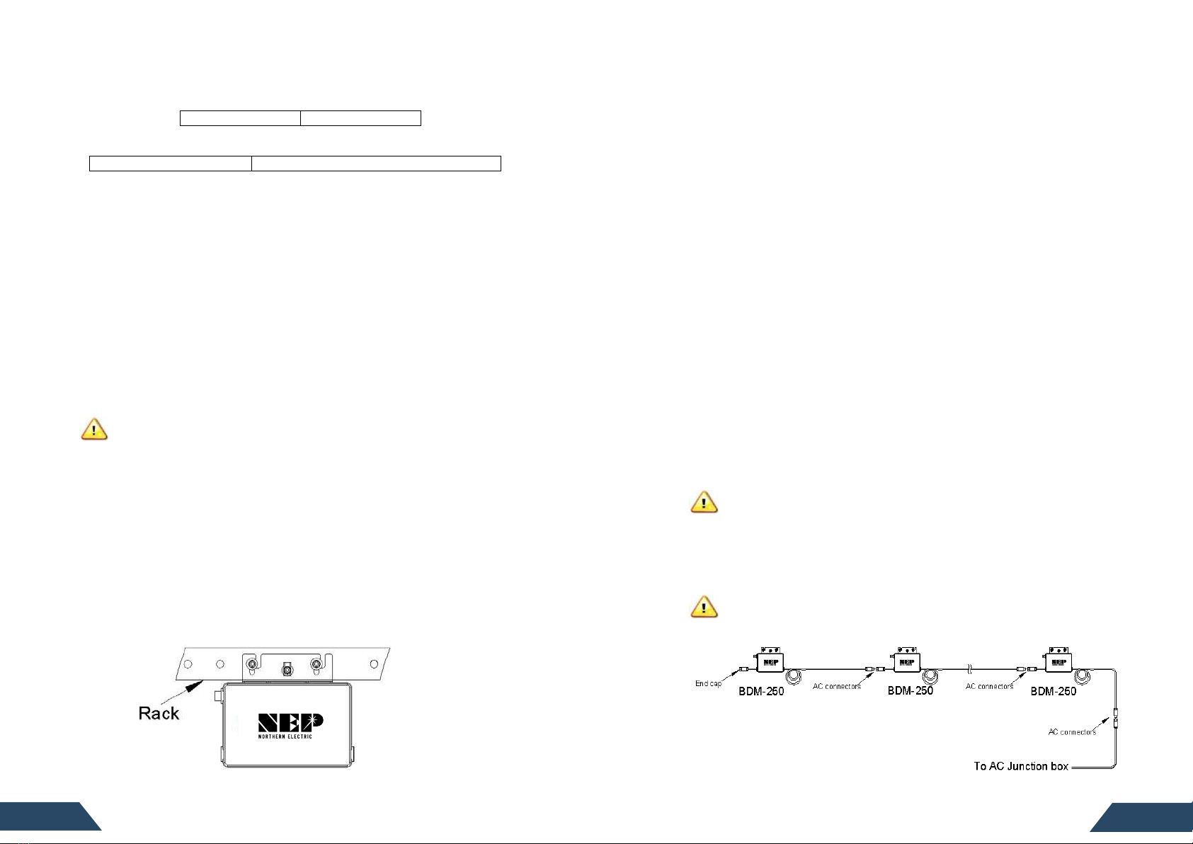
2. Plug the AC connector of the rst BDM-250 into the connector of the next
BDM-250, and so forth, to form a connuous AC branch circuit. Please check the
BDM-250 rang label for the maximum allowable number of BDM-250 on one
AC branch circuit. For the chain of the BDM-250 micro inverters thus formed,
one end of the AC cable should be protected by a CAP (refer to the BDM-250
accessories). For the other end of the AC cable, it should be connected to an AC
juncon box through a tail cable (refer to the BDM-250 accessories). For
BDM-250-240A and BDM-250-208A, the L1 wire (red), L2 wire (black) and
neutral wire (blue) in the AC cable should be connected to the corresponding
phases of the main grid through the AC juncon box. For BDM-250-AU and
BDM-250-EU, the L1 wire (red) and L2 wire (black) should be connected to the L
and N phases of the main grid respecely at the AC juncon box. For
BDM-250-AU and BDM-250-EU, the neutral wire (blue) is unused and should be
terminated in the AC juncon box on an unused connector. It should NOT be
connected to L1 (red), or L2 (black), or earth, or any other wires.
WARNING: DO NOT EXCEED THE MAXIMUM NUMBER OF BDM-250 IN AN AC BRANCH
CIRCUIT, AS DISPLAYED ON THE UNIT-RATING LABEL. EACH BDM-250 AC BRANCH CIRCUIT
MUST BE SOURCED FROM A DEDICATED BRANCH CIRCUIT PROTECTED BY A 15A MAXIMUM
BREAKER.
3. Install a protece end cap on the open AC connector of the last BDM-250
in the AC branch circuit.
WARNING: MAKE SURE PROTECTIVE END CAPS HAVE BEEN INSTALLED ON ALL UNUSED
AC CONNECTORS. UNUSED AC BDM-250 WIRE HARNESS CONNECTORS ARE LIVE WHEN
THE SYSTEM IS ENERGIZED BY THE UTILITY SYSTEM.
07
0 6
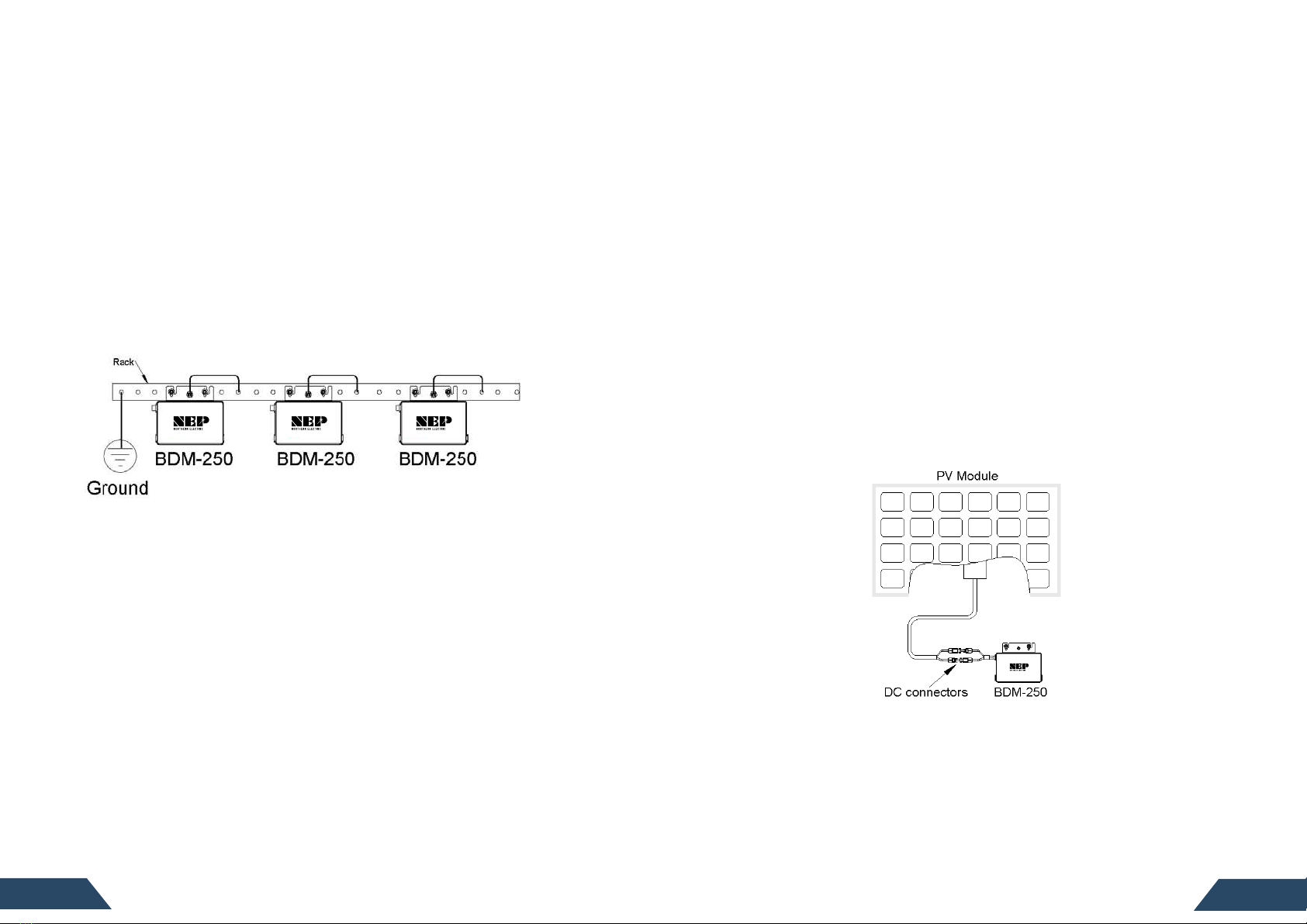
Step 4 – Grund the System
Each BDM-250 comes with a ground clip that can accommodate a 6-8 AWG
conductor. If you are not using grounding washers to ground the BDM-250
chassis as described in step2, route a connuous GEC through each of the
BDM-250 to the NEC approved AC grounding electrode. The racking and module
could be grounded to this conductor using a crimp connecon. An alternae
method would be to connect the BDM-250 to the grounded racking using a
grounding washer approved for the racking.
NOTE: The neutral wire (blue) in the AC cable is NOT bonded to earth and
earth/ground connecon is not provided via the AC cable through the
micro-inverter. The earth/ground connector on the enclosure of micro-inverter
shall be reliably connected to the earth; otherwise there will be a risk of person
shock hazard or re hazard. The ground conductor size is recommended with at
least 4mm2and should be larger than live conductor cross secon area. Refer
to local regulaon for minimum size requirement for ground conductor size.
Step 5 – Cmplete the cnnecn map and cnnect the PV Mdules
BDM-250 connecon Map is a diagrammac representaon of the physical
locaon of each BDM-250 in your PV installaon. The virtual array in NEP micro
inverter gateway BDG-256 is created from the map you create.
Cmplete the cnnecn map
Each BDM-250 has a removable serial number located on the individual label.
Enter the unique address contained in part of the serial number into a
BDG-256, and correspond it to a number in the connecon map.
Cnnect the PV Mdules
Completely install all BDM-250 and all system inter-wiring connecons prior to
installing the PV modules.
1. Mount the PV modules above their corresponding BDM-250. Each BDM-250
comes with two oppositely sexed DC connectors.
2. First connect the posie DC wire from the PV module to the posiely marked
DC connector (male pin) of the BDM-250. Then connect the negae DC wire
from the PV module to the negaely marked DC connector (female socket) of
the BDM-250. Repeat for all remaining PV modules using one BDM-250 for each
module.
09
0 8
5. COMMISSIONING
WARNING: CONNECT BDM-250 TO THE ELECTRICAL UTILITY GRID ONLY AFTER RECEIVING
PRIOR APPROVAL FROM THE UTILITY COMPANY.
WARNING: BE AWARE THAT ONLY QUALIFIED PERSONNEL CAN CONNECT BDM-250 TO THE
ELECTRICAL UTILITY GRID.
WARNING: ENSURE THAT ALL AC AND DC WIRING IS CORRECT. ENSURE THAT NONE OF THE
AC AND DC WIRES IS PINCHED OR DAMAGED. ENSURE THAT ALL JUNCTION BOXES ARE
PROPERLY CLOSED.
Following these steps to commission the BDM-250 PV system:
1. Turn on the AC disconnects or circuit breakers on each BDM-250 AC branch circuit.
2. Turn on the main uty-grid AC circuit breaker. Your system will start producing
power aer a few minutes wait me.
3. The BDM-250 will start to send performance data over the power lines using
power line communicaon (PLC) to the BDG-256. The me required for each
BDM-250 in the system to communicate to the BDG-256 will vary with the number
of BDM-250 in the system.
10
6. OPERATING INSTRUCTIONS
The BDM-250 is powered on when sucient DC voltage from the module is applied.
The status LED will start ashing aer suicient DC power is applied as an indicaon
that the BDM-250 is live.
Status: standby
The LED light is on by 2 second, and oby 2 seconds.
Status: prducing pwer
The LED light is on by 1 second, and oby 1 second.
Status: prducing pwer and cmmunicang with BDG-256
The LED light is on by 0.5 second, and oby 0.5 second.
In case of fault, BDM-250 has mulple protece funcons and stops output power.
The fault message may be sent to a connected BDG-256 gateway through power
line communicaon. The error message is displayed on the screen of BDG-256
gateway by a 16-bit error code.
Errr cde Errr
Bit-0 DC over voltage
Bit-1 DC under voltage
Bit-2 hardware error
Bit-3 Inverter over voltage
Bit-4 Frequency over
Bit-5 Frequency under
Bit-6 AC voltage RMS over
Bit-7 AC voltage RMS under
Bit-8 Peak AC voltage over
Bit-9 AC current RMS over
Bit-10 Peak AC current over
Bit-11 Temperature over
Bit-12 ADC error
Bit-13 GFDI fault indicator
Bit-14 Relay fault (BDM-250-AU/BDM-250-EU only)
Bit-15 PLC Communicaon Error
11
10

12
7. TROUBLESHOOTING AND MAINTENANCE
WARNING: DO NOT ATTEMPT TO REPAIR THE BDM-250; IT CONTAINS NO
USER-SERVICEABLE PARTS. IF TROUBLESHOOTING METHODS FAIL, PLEASE RETURN THE
BDM-250 TO YOUR DISTRIBUTOR FOR MAINTENANCE.
WARNING: NEVER DISCONNECT THE DC WIRE CONNECTORS UNDER LOAD. ENSURE THAT
NO CURRENT IS FLOWING IN THE DC WIRES PRIOR TO DISCONNECTING. AN OPAQUE
COVERING MAY BE USED TO COVER THE MODULE PRIOR TO DISCONNECTING
WARNING: ALWAYS DISCONNECT AC POWER BEFORE DISCONNECTING PV MODULE WIRES
FROM BDM-250. THE AC CONNECTOR OF THE FIRST BDM-250 IN A BRANCH CIRCUIT IS
SUITABLE AS A DISCONNECTING MEANS ONCE THE AC BRANCH CIRCUIT BREAKER IN THE LOAD
CENTER HAS BEEN OPENED.
WARNING: BDM-250 IS POWERED BY DC POWER FROM PV MODULES. MAKE SURE YOU
DISCONNECT THE DC CONNECTIONS AND RECONNECT DC POWER TO WATCH FOR THE TWO
SECONDS LED ON AND TWO SECONDS LED OFF AFTER DC IS APPLIED.
LED indican f errr
●Errr reprt: ACr DC fault
The LED light is on by 4 second, and oby 4 seconds.
●Errr reprt: GFDI fault
The LED light stays on.
Trubleshng an inperable BDM-250
To troubleshoot an inoperable BDM-250, follow the steps in the order shown:
1. Check the connecon to the ulity grid. Verify that the uty voltage and
frequency are within allowable ranges shown in the label of BDM-250.
2. Verify uty power is present at the inverter in queson by removing AC, then DC
power. Never disconnect the DC wires while the BDM-250 is producing power.
Re-connect the DC module connectors, and then watch for the LED blinks.
3. Check the AC branch circuit interconnecon harness between all the BDM-250.
Verify that each inverter is energized by the ulity grid as described in the
previous step.
4. Make sure that any AC disconnects are funconing properly and are closed.
5. Verify the PV module DC voltage is within the allowable range shown in the label
of BDM-250.
6. Check the DC connecons between the BDM-250 and the PV module.
7. If the problem persists, please call customer support at NEP.
WARNING: DO NOT ATTEMPT TO REPAIR THE BDM-250; IT CONTAINS NO
USER-SERVICEABLE PARTS. IF TROUBLESHOOTING METHODS FAIL, PLEASE RETURN THE
BDM-250 TO YOUR DISTRIBUTOR FOR MAINTENANCE.
Discnnecng a BDM-250 frm the PV Mdule
To ensure the BDM-250 is not disconnected from the PV modules under load, adhere
to the following disconnecon steps in the order shown:
1. Disconnect the AC by opening the branch circuit breaker.
2. Disconnect the rst AC connector in the branch circuit.
3. Cover the module with an opaque cover.
4. Using a DC current probe, verify there is no current owing in the DC wires between
the PV module and the BDM-250.
5. Care should be taken when measuring DC currents, most clamp-on meters must be
zeroed rst and tend to driwith me.
6. Disconnect the PV module DC wire connectors from the BDM-250.
7. Remove the BDM-250 from the PV array racking.
Installing a replacement BDM-250
1. Aach the replacement BDM-250 to the PV module racking using hardware
recommended by your module racking vendor. If you are using grounding washers
(e.g., WEEB) to ground the chassis of the BDM-250, the old grounding washer should
be discarded, and a new grounding washer must be used when installing the
replacement BDM-250. Torque the BDM-250 fasteners to the values listed below:
1/4” mounng hardware – 45 in-lbs minimum
5/16” mounng hardware – 80 in-lbs minimum.
2. If you are using agrounding electrode conductor to ground the BDM-250 chassis,
aach the grounding electrode conductor to the BDM-250 ground clamp.
3. Connect the AC cable of the replacement BDM-250 and the neighboring BDM-250
to complete the branch circuit connecons.
4. Complete the connecon map and connect the PV Modules.
1) Complete the connecon map
2) Each BDM-250 has a removable serial number located on the individual label.
Enter the unique address contained in part of this serial number into a BDG-256,
and correspond it to a number in the connecon map.
3) Connect the PV Modules
4) Completely install all BDM-250 and all system inter-wiring connecons prior to
installing the PV modules.
a) Mount the PV modules above their corresponding BDM-250. Each
BDM-250 comes with two oppositely sexed DC connectors.
b) First connect the posie DC wire from the PV module to the posiely
marked DC connector (male pin) of the BDM-250. Then connect the negae
DC wire from the PV module to the negaely marked DC connector (female
socket) of the BDM-250. Repeat for all remaining PV modules using one
BDM-250 for each module.
13
12

8. SPECIFICATION
MODEL BDM-250-240A BDM-250-208A
INPUT(DC)
Max Recommended PV Power (Wp) 285
Max DC Open Circuit Voltage (Vdc) 60
Max DC Input Current (Adc) 12
MPPT Tracking Accuracy >99.5%
MPPT Tracking Range (Vdc) 22-55
OUTPUT(AC)
Rated AC Output Power (Wp) 220
Nominal Power Grid Voltage (Vdc) 240 / 220 208/220
Allowable Power Grid Voltage (Vdc) 211-264/198-253 186-228/198-253
Allowable Power Grid Frequency (Hz) 59.3-60.5/45.5-52.5
THD <3% (at rated power)
Power Factor (cos phi, xed) >0.99%
SYSTEM
EFFICIENCY
Peak Eciency 96.3% 95.70%
CEC Eciency 95%
Night Time Tare Loss (Wp) 0.17
PROTECTION
FUNCTIONS
Over/Under Voltage Protecon Yes
Over/Under Frequency Protecon Yes
An-Islanding Protecon Yes
Over Current Protecon Yes
Reverse DC Polarity Protecon Yes
GFDI Integrated
Overload Protecon Yes
Protecon Degree NEMA-6
Environment Temperature -40℃——+65℃
OTHER
PARAMETERS
Environment Humidity 100%, condensaon
Display LED LIGHT
Communicaons Power Line
Dimension (D-W-H mm) 230*138*35
Weight (Kg) 2
MODEL
BDM-250-EU
BDM-250-AU
INPUT(DC)
Max Recommended PV Power (Wp)
285
Vmax PV (absolute maximum) (Vdc)
60
PV Input Operang Voltage Range (Vdc)
22-55
Maximum Operang PV Input Current (Adc)
12
MPPT Tracking Accuracy
>99.5%
Isc PV (absolute maximum) (Adc)
14
Maximum Inverter Backfeed Current to the Array (Adc)
0
OUTPUT(AC)
Rated AC Output Power (W)
220
Nominal Power Grid Voltage (Vac)
230
Current (maximum connuous) (Aac)
1.0
Current (inrush) (Peak and Duraon)
12A, 15us
Nominal Frequency (Hz)
50
Power Factor (cos phi, xed)
>0.99
Maximum Output Fault Current (Aac)
2.2A peak
Maximum Output Overcurrent Protecon (Aac)
6.3
Maximum Number of Units Per Branch
15
SYSTEM
EFFICIENCY
Peak Eciency
96.30%
CEC Eciency
95.0%
Night Time Tare Loss (Wp)
0.17
PROTECTION
FUNCTIONS
Over/Under Voltage Protection
Yes
Over/Under Frequency Protecon
Yes
An-Islanding Protecon
Yes
Over Current Protecon
Yes
Reverse DC Polarity Protecon
Yes
Overload Protecon
Yes
GFDI
Integrated
Protecve Class
I
IP Rang per Part 1
IP67
OTHER
PARAMETERS
Environment Temperature
-40℃~ +65℃
Environment Category
Indoor and outdoor
Wet Locaon
SUITABLE
Polluon Degree
PD 3
Environment Humidity
100%, condensaon
Maximum Altude
2000 M
Overvoltage Category
II(PV), III (AC MAINS)
Display
LED LIGHT
Communicaons
POWERLINE
Dimension (D-W-H mm)
230*138*35
Weight(Kg)
2
Product Safety Compliance
IEC/EN 62109-1
Grid Code Compliance* (Refer to the label for the
detailed grid code compliance)
VDE-AR-N 4105*
VDE V 0126-1-1/A1
G83/2
AS 4777.2 & AS
Note: For grid code VDE-AR-N 4105, maximum 3.68kVA PV plant is limited. The
grid protecon report and seng are readable from the gateway.
For grid code G83/2, maximum 16A per phase is limited. The grid protecon
report and seng are readable from the gateway.
15
14

9. WARRANTY AND PRODUCTION INFORMATION
What des this warranty cver and hw lng des it last?
This Limited Warranty is provided by Northern Electric & Power Co. Ltd (NEP) and
covers defects in workmanship and materials in your BDM-250 Grid-Tied Inverter. This
Warranty Period lasts for 10 years from the date of purchase at the point of sale to
you, the original end user customer, unless otherwise agreed in wring. You will be
required to demonstrate proof of purchase to make warranty claims.
This Limited Warranty is transferable to subsequent owners but only for the
unexpired poron of the Warranty Period. Subsequent owners also require original
proof of purchase as described in "What proof of purchase is required?"
What will NEP d?
During the Warranty Period, NEP will, at its opon, repair the product (if economically
feasible) or replace the defece product free of charge, provided that you nofy NEP
of the product defect within the Warranty Period, and provided that NEP through
inspecon establishes the existence of such a defect and that it is covered by this
Limited Warranty.
NEP will, at its opon, use new and/or recondioned parts in performing warranty repai
r
and building replacement products. NEP reserves the right to use parts or products of
original or improved design in the repair or replacement. NEP repairs or replaces a
product, its warranty connues for the remaining poron of the original Warranty
Period or 90 days from the date of the return shipment to the customer, whichever is
greater. All replaced products and all parts removed from repaired products become the
property of NEP.
Hw dyu get service?
If your product requires troubleshoong or warranty service, contact your merchant. If
you are unable to contact your merchant, or the merchant is unable to provide service,
contact NEP directly at:
Nrthern Electric & Pwer C. Ltd
Address:NO.1 Anhe Rd Tsingtao Export Processing Zone, Tsingtao, China 266113
Phne:+86 532 87963900
Fax:+86 532 81100917
What des this warranty nt cver?
Claims are limited to repair and replacement or if in NEP's discreon that is not
possible, reimbursement up to the purchase price paid for the product. NEP will be
liable to you only for direct damages suered by you and only up to a maximum
amount equal to the purchase price of the product.
This Limited Warranty does not warrant uninterrupted or error-free operaon of the
product or cover normal wear and tear of the product or costs related to the removal,
installaon, or troubleshoong of the customer's electrical systems. This warranty
MODEL BDM-250-LV
INPUT(DC)
Max Recommended PV Power (Wp)
285
Vmax PV (absolute maximum) (Vdc)
60
PV Input Operang Voltage Range (Vdc)
22-55
Maximum Operang PV Input Current (Adc)
12
MPPT Tracking Accuracy
>99.5%
Isc PV (absolute maximum) (Adc)
14
Maximum Inverter Backfeed Current to the Array (Adc)
0
OUTPUT(AC)
Rated AC Output Power (W)
220
Nominal Power Grid Voltage (Vac)
127
Current (maximum connuous) (Aac)
1.73
Current (inrush) (Peak and Duraon)
12A, 15us
Nominal Frequency (Hz)
60
Power Factor (cos phi, xed)
>0.99
Maximum Output Fault Current (Aac)
4.2A peak
Maximum Output Overcurrent Protecon (Aac)
10
Maximum Number of Units Per Branch
8
SYSTEM
EFFICIENCY
Peak Eciency
96.30%
CEC Eciency
95.0%
Night Time Tare Loss (Wp)
0.17
PROTECTION
FUNCTIONS
Over/Under Voltage Protecon
Yes
Over/Under Frequency Protecon
Yes
An-Islanding Protecon
Yes
Over Current Protecon
Yes
Reverse DC Polarity Protecon
Yes
Overload Protecon
Yes
GFDI
Integrated
Protecve Class
I
IP Rang per Part 1
IP67
OTHER
PARAMETERS
Environment Temperature
-40℃~ +65℃
Environment Category
Indoor and outdoor
Wet Locaon
SUITABLE
Polluon Degree
PD 3
Environment Humidity
100%, condensaon
Maximum Altude
2000 M
Overvoltage Category
II(PV), III (AC MAINS)
Display
LED LIGHT
Communicaons
POWERLINE
Dimension (D-W-H mm)
230*138*35
Weight(Kg)
2
Product Safety Compliance UL 1741
CSA C22.2 No. 107.1
Grid Code Compliance* (Refer to the label for the
detailed grid code compliance)
IEEE 1547
17
16
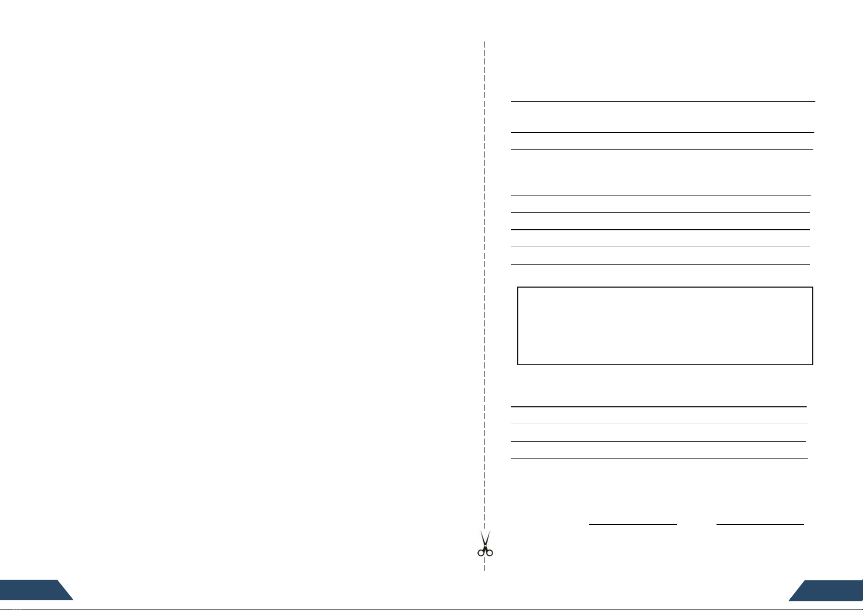
Warranty Card
Custmer Infrman
Name:
Address:
City: State: Zip Code:
Tel: Fax: E-mail:
System Infrman
Fault Product(s) Serial Numbers:
System Commissioning Date: Product Models:
No. of Products Used: Bill of Lading Date:
Fault Product(s) Quanes: Fault Time/Date:
Fault Message(s) or Code(s):
Brief Fault Descripon and Photos:
Installan Infrman
Modules Used:
Modules Quanty: Inverters quanty per string:
Installaon Company Name:
Installer Name:
For the informaon on our warranty terms and condions,
please see our website: www.northernep.com/en
All elds must be completed in order to process claim.
Custmer Signature: Date:
*All rights reserved by NEP. This informaon is subject to changes without noce.
does not apply to and NEP will not be responsible for any defect in or damage to:
a) the product if it has been misused, neglected, improperly installed, physically
damaged or altered, either internally or externally, or damaged from improper
use or use in an unsuitable environment; b) the product if it has been subjected
to re, water, generalized corrosion, biological infestaons, or input voltage that
creates operang condions beyond the maximum or minimum limits listed in
the NEP product specicaons including high input voltage fromgenerators and
lightning strikes; c) the product if repairs have been done to it other than by NEP
or its authorized service centers (hereaer "ASCs"); d) the product if it is used as
a component part of a product expressly warranted by another manufacturer; e)
the product if its original idencaon (trade-mark, serial number) markings
have been defaced, altered, or removed; f) the product if it is located outside of
the country where it was purchased; and g) any consequenal losses that are
aributable to the product losing power whether by product malfuncon,
installaon error or misuse.
Disclaimer Prduct
THIS LIMITED WARRANTY IS THE SOLE AND EXCLUSIVE WARRANTY PROVIDED BY NEPIN
CONNECTION WITH YOUR NEP PRODUCT AND IS, WHERE PERMITTED BY LAW, IN LIEU OF ALL
OTHER WARRANTIES, CONDITIONS, GUARANTEES, REPRESENTATIONS, OBLIGATIONS AND
LIABILITIES, EXPRESS OR IMPLIED, STATUTORY OR OTHERWISE IN CONNECTION WITH THE
PRODUCT, HOWEVER ARISING (WHETHER BY CONTRACT, TORT, NEGLIGENCE, PRINCIPLES OF
MANUFACTURER'S LIABILITY, OPERATION OF LAW, CONDUCT, STATEMENT OR OTHERWISE),
INCLUDING WITHOUT RESTRICTION ANY IMPLIED WARRANTY OR CONDITION OF QUALITY,
MERCHANTABILITY OR FITNESS FOR A PARTICULAR PURPOSE. ANY IMPLIED WARRANTY OF
MERCHANTABILITY OR FITNESS FOR A PARTICULAR PURPOSE TO THE EXTENT REQUIRED
UNDER APPLICABLE LAW TO APPLY TO THE PRODUCT SHALL BE LIMITED IN DURATION TO THE
PERIOD STIPULATED UNDER THIS LIMITED WARRANTY.
IN NO EVENT WILL NEP BE LIABLE FOR: (a) ANY SPECIAL, INDIRECT, INCIDENTAL OR
CONSEQUENTIAL DAMAGES, INCLUDING LOST PROFITS, LOST REVENUES, FAILURE TO REALIZE
EXPECTED SAVINGS, OR OTHER COMMERCIAL OR ECONOMIC LOSSES OF ANY KIND, EVEN IF
NEP HAS BEEN ADVISED, OR HAD REASON TO KNOW, OF THE POSSIBILITY OF SUCH DAMAGE,
(b) ANY LIABILITY ARISING IN TORT, WHETHER OR NOT ARISING OUT OF NEP'S NEGLIGENCE,
AND ALL LOSSES OR DAMAGES TO ANY PROPERTY OR FOR ANY PERSONAL INJURY OR
ECONOMIC LOSS OR DAMAGE CAUSED BY THE CONNECTION OF A PRODUCT TO ANY OTHER
DEVICE OR SYSTEM, AND (c) ANY DAMAGE OR INJURY ARISING FROM OR AS A RESULT OF
MISUSE OR ABUSE, OR THE INCORRECT INSTALLATION, INTEGRATION OR OPERATION OF THE
PRODUCT.
IF YOU ARE A CONSUMER (RATHER THAN A PURCHASER OF THE PRODUCT IN THE COURSE OF A
BUSINESS) AND PURCHASED THE PRODUCT IN A MEMBER STATE OF THE EUROPEAN UNION, THIS
LIMITED WARRANTY SHALL BE SUBJECT TO YOUR STATUTORY RIGHTS AS A CONSUMER UNDER
THE EUROPEAN UNION PRODUCT WARRANTY DIRECTIVE 1999/44/EC AND AS SUCH DIRECTIVE
HAS BEEN IMPLEMENTED IN THE EUROPEAN UNION MEMBER STATE WHERE YOU PURCHASED
THE PRODUCT. FURTHER, WHILE THIS LIMITED WARRANTY GIVES YOU SPECIFIC LEGAL RIGHTS,
YOU MAY HAVE OTHER RIGHTS WHICH MAY VARY FROM EU MEMBER STATE TO EU MEMBER
STATE OR, IF YOU DID NOT PURCHASE THE PRODUCT IN AN EU MEMBER STATE, IN THE COUNTRY
YOU PURCHASED THE PRODUCT WHICH MAY VARY FROM COUNTRY TO COUNTRY AND
JURISDICTION TO JURISDICTION.
19
18

USA
Add:1781 Riverview Ave., Tracy, CA 95377
Australia
Address: 9 Meander Grove, Cameron Park, NSW2285
China
Add: No.1 Anhe Rd Tsingtao Export Processing Zone, Tsingtao, China 266113
TEL: +86 532 87963900
FAX: +86 532 81100917
This manual suits for next models
4
Table of contents
Other NEP Inverter manuals


Popular Inverter manuals by other brands


Heat Controller
Heat Controller VMH 09 SD Installation, operation & maintenance manual

Sourcetronic
Sourcetronic ST130 Series user manual

Projoy Electric
Projoy Electric PEFS-PL Series user manual

Allmand
Allmand Maxi-Power MP25 T4F Operator's manual

EZIHEAT
EZIHEAT MSC90 user manual

Redback
Redback ST10000 owner's guide

Hitachi
Hitachi L300P Series instruction manual

Inverter
Inverter WVC Series user manual

OWT Industries
OWT Industries Black Max BM10700 manual

THOR
THOR PW Series instruction manual

Generac Power Systems
Generac Power Systems PRIMEPACT 50 04164-3 owner's manual

Wagan
Wagan PURE SINE WAVE INVERTER 9754 user manual