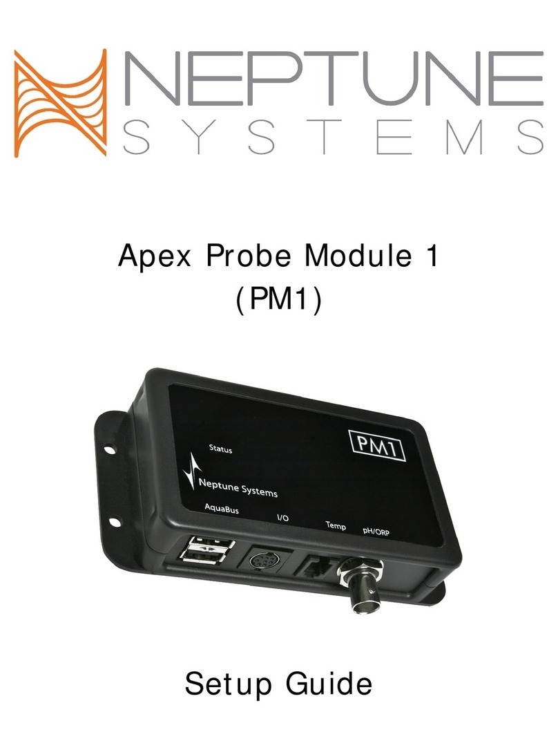
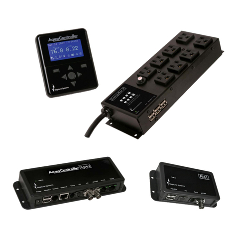
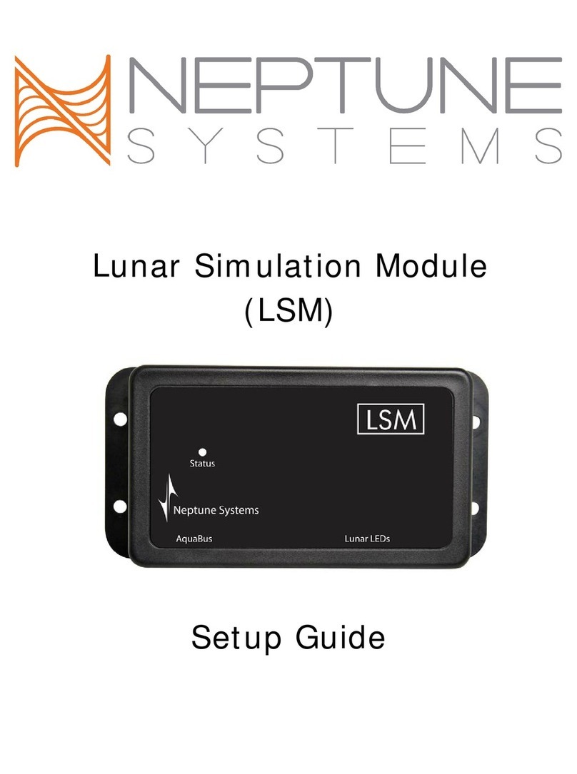
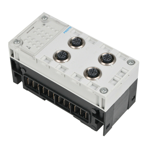
Neptune Systems AI Wireless Module User manual

AI Wireless Module
(AWM)
Setup Guide

Table of Contents
AI WIRELESS MODULE – INTRODUCTION....................................................................... 3
FEATURES ...................................................................................................................... 3
PHYSICAL INSTALLATION .............................................................................................. 3
Initial Connections..............................................................................................................4
Startup.............................................................................................................................4
VERIFY THE INSTALLATION ........................................................................................... 4
PAIRING THE AWM WITH YOUR LIGHTS ........................................................................ 5
PROGRAMMING LIGHTS ................................................................................................. 5
Advanced Program ExampleS ..............................................................................................7
NEPTUNE SYSTEMS LIMITED WARRANTY..................................................................... 10
*Hydra, Hydra FiftyTwo, Vega, Vega Blue and AquaIllumination (AI) are registered trademarks of C2
Development Inc.

AI Wireless Module (AWM) - Setup Guide Page 3
AI WIRELESS MODULE – INTRODUCTION
Congratulations on your purchase of the AquaController Apex expansion accessory. The AquaController Apex AI
Wireless Module (AWM) provides the ability to control AI Vega® and Hydra® series LED fixtures from your
AquaController system. This enables complete integration with all the control and functionality offered by the
Apex system – modify your lighting plan based on time of day or day of week. Change colors through the day
from dim in the morning to bright white during the middle of the day.
The AquaController Apex System delivers an expandable, professional quality aquarium controller at hobbyist
prices. The AquaController Apex is the most flexible, expandable system on the market today.
This manual outlines the set up and configuration of AI Wireless LED lights using the AWM via programming the
Apex AquaController using its built-in web interface. This process will be made significantly simpler in the very
near future as our new cloud-based service, Apex Fusion, is made available.
FEATURES
•Wirelessly controls up to 12 AI Vega and Hydra LED fixtures – add additional AWM modules to control
more.
•19 different wireless frequencies that insure you get reliable communications.
•Lighting modes can be changed based on conditions and events throughout the day using powerful
Apex programming commands.
•Supports ‘weather’ profiles – clouds and lightning can be incorporated in your lighting strategy
•The AWM attaches to and is powered by the Apex system via AquaBus.
•Automatic Plug N Play for easy setup and configuration.
•Lights can be dynamically added/removed from the system.
•Upgradable AWM firmware through AquaBus via the Apex Base Module.
•Multi-color LED Status and Wireless Status indicators.
•2 AquaBus ports for flexible system connections.
•Comes with a 3' AquaBus cable.
•Compatible with all Apex systems – Apex, Lite and Jr.
PHYSICAL INSTALLATION
WARNING: Your Apex Base Module must be running firmware version 4.30 or higher to support the AI
Wireless Module (AWM). The current firmware version can be checked from the Apex Display on the Self
Test screen. If needed, please upgrade the Apex Base Module firmware before proceeding with the installation.
See the Apex Setup and Programming Guide for firmware upgrade instructions.
The AquaController AWM should be securely mounted in a location free from moisture. Use wood screws
through the mounting tabs of the expansion module case or if mounting on drywall, use drywall anchors
(mounting hardware not included).
•Mount the AWM away from other wireless devices to ensure reliable wireless communication.
•Mount all modules above the water line of the aquarium.
•Be sure to utilize drip loops on all power cords, AquaBus cables and probe cables.

AI Wireless Module (AWM) - Setup Guide Page 4
WARNING: Water damage will void your warranty! Mount all modules in locations safe from moisture
exposure.
INITIAL CONNECTIONS
Plug one end of the included AquaBus cable into one of the AquaBus ports on the AWM and the other end into
an available AquaBus port on your existing Apex system. It makes no difference which AquaBus port or module
is used and you do not need to power down the system when connecting AquaBus accessories as the system is
plug-and-play.
WARNING: NEVER plug standard USB devices into any AquaBus connector or AquaBus accessories into
computer USB ports. Damage to the AquaBus accessory and/or USB device may result.
STARTUP
As soon as the AWM is connected to an active AquaBus, the module will power up and begin to
initialize. When first connected to an AquaController Base Module (through the AquaBus), the
AWM will automatically be assigned an AquaBus address and be added to the AquaController
configuration. The LED Status indicator on the module will flash yellow while it is being
initialized. Once initialized, the LED Status indicator will be solid green. The LED Status
indicator will flash yellow when if communication with the AquaController Base Module is lost.
VERIFY THE INSTALLATION
Verify the AWM was initialized and added to the AquaController Apex configuration:
Apex Display: Setup – Module Setup – Modify Name – from this screen, you can see all AquaBus
modules installed on the system.
Web Interface: Configuration – Module Setup – Verify the AWM is listed in the Apex Module List (see
below – note your address may be different than the 003 in the screenshot).
In the unlikely event that your AWM firmware needs to be updated, it will show (OLD) in the ‘SW Rev’ column.
Updating the firmware is easily done using the Module Setup web page.
1. Select your AWM module
2. Select the ‘Update Firmware’ radio button
3. Click ‘Submit Module Change’

AI Wireless Module (AWM) - Setup Guide Page 5
There is nothing to download – any firmware update will be contained in your controller’s software.
PAIRING THE AWM WITH YOUR LIGHTS
Once you have added the AWM to your Aquabus and have a solid green light you need to pair it with your LED
fixture(s). A single AWM can control up to 12 fixtures.
1) From the Module Setup web page, select the AWM module. Notice the button ‘Attach’.
2) Power up your fixture. Once the light starts you’ll get a solid red light
3) Press and hold the red reset button to the right of the power connector until the status light on the
fixture blinks RED/GREEN – about 7 seconds.
4) Click the ‘Attach’ button on the Module Setup page
5) If pairing was successful, the status light on the LED fixture should turn solid green and the Wireless
Status light on the AWM module should also go to solid green. Light will alternate green/yellow when
receiving commands from the AWM.
At this point your controller will create an outlet for your fixture called ‘Hydra_X_1’ where ‘X’ represents the
Aquabus number assigned to your AWM. If this was the second or third fixture the ‘1’would be ‘2’ or ‘3’
respectively (up to 12).
Status light on the Hydra fixture. Reset button
•Red – no communications to the AWM
•Green/Yellow – normal communications with the AWM
•Red/Green flashing – ready to pair with the AWM
PROGRAMMING LIGHTS
Once you’ve established communications with the LED fixture, it’s time to program your lights. Now would be a
good time to add the new light outlet to your Dashboard (for instructions on how to do this, see the
Comprehensive Reference Manual or visit the Neptune Community Forum at http://forum.neptunesystems.com
and look in the Dashboard forum).

AI Wireless Module (AWM) - Setup Guide Page 6
First, test your fixture by turning your Hydra light outlet to ON using the Dashboard. Your fixture should turn
on with 100% intensity, all colors – maximum brightness. If so, communications is working and you can set
the outlet to OFF for now until it’s programmed.
Your light fixture has multiple colored LED’s. Each color channel can be independently controlled in terms of its
intensity (0 – 100%). In addition, the overall intensity or brightness of the fixture can be controlled, again 0 –
100%. This is established using profiles. You can have up to 32 different profiles defined with the Apex
controller. Using profiles, you can define a color assortment for midday and a different color profile for
mornings or evenings.
Defining your profiles will be the first step in programming and you do this from the Configuration – Profiles
Setup web page. Follow these steps:
1. Select an unused profile (default names are PF1 – PF32).
2. Change the default name to a unique profile name. Note that profile names are case sensitive!
3. Select ‘Vega/Hydra’ for the Control Type. You will see all the possible colors along with
begin/end overall intensity and Ramp Time. We’ll use these in just a minute.
4. The following chart shows what colors/#LEDs are available with which fixture – colors that your
fixture doesn’t support can just be left at 0
Color
Hydra
Hydra
FiftyTwo
Vega
Vega Blue
Cool White
X4
X16
X4
X4
Warm White
O
O
Neutral White
O
O
Green
X2
X4
X1
O
Violet
X2
X4
O
O
Red
X2
X4
X1
O
Blue
X4
X4
Deep Blue
X4
X8
X4
X4
Royal Blue
X4
X12
X6
X8
UV
X2
X4
O
O
X = Standard color and number of LED’s in that color
O = Optional with ‘Power Pucks’
5. Begin entering your selected color intensities skipping those colors your fixture does not support.
Here’s some intensities you might want to start with – note that unless you’re replacing existing LED’s
it’s best to work up to these levels, especially UV. Watch your corals carefully for any signs of bleaching
or browning and adjust your intensities down/up accordingly:
•Cool White 45%
•Green 49%
•Violet 58%
•Red 49%
•Deep Blue 55%
•Royal Blue 55%
•UV 59%

AI Wireless Module (AWM) - Setup Guide Page 7
6. ‘Start Overall Intensity’ and ‘End Overall Intensity’ are used to ramp your fixture up or down at
the beginning of the day to simulate sunrise or at the end to simulate sunset. Again, watch
your corals for signs of bleaching or browning and adjust intensities accordingly.
7. ‘Ramp Time’ is the duration of the ramp in minutes. For example, begin/end intensities of 30
and 100 with a ramp time of 60 will take your fixture from 30% to 100% over a 60 minute
period.
8. ‘Update’ to save.
Once you’ve created all your profiles, you can begin to reference them in an outlet program. Remember, profile
(and outlet) names are case-sensitive.
Basic Lighting Program:
Enter this against your ‘Hydra’ outlet created when you paired your AWM module with your light. You can
rename the outlet as you wish. Select ‘Advanced’ for the Control Type.
Fallback OFF
Set OFF
If Time 08:00 to 10:00 Then RampUp
If Time 10:00 to 16:00 Then Day
If Time 16:00 to 18:00 Then RampDn
The above program assumes you’ve created three profiles named ‘RampUp’, ‘Day’ and ‘RampDn’. Both of the
ramp profiles have a Ramp Time of 120 minutes. RampUp starts at 20% and ends at 100%, RampDn just the
opposite. The profile Day has a start and end intensity of 100 and a Ramp Time of 1 since there really isn’t any
ramp.
ADVANCED PROGRAM EXAMPLES
The following examples show you how you can apply more controller features to your lighting strategy.
Weekend Override:
In this example, we want to use the basic profiles above but we want the lights to come on 1 hour earlier on
the weekend. To do this, we’re going to use the Day of Week (DoW) command. In addition we want to turn
OFF our lights if the tank gets too hot, we want to turn them ON if the tank gets too cold (get heat any way we
can) and finally, to avoid them turning ON/OFF quickly in a power failure, put a minimum amount of time to
keep them off so they don’t get damaged:
Fallback ON
Set OFF
If Time 07:00 to 09:00 Then RampUp
If DoW -MTWTF- Then OFF
If Time 08:00 to 09:00 Then RampUP
If Time 09:00 to 16:00 Then Day
If Time 16:00 to 18:00 Then RampDn
If Temp > 82.0 Then OFF
If Temp < 76.0 Then ON
Min Time 010:00 Then OFF

AI Wireless Module (AWM) - Setup Guide Page 8
Moonlights:
In this example, we create a profile called ‘moonlight’ with a 1% intensity on the Deep Blue channel and 6% on
the UV channel, turning our Hydra into a moonlight:
1. Create a profile, name it ‘moonlight’.
2. Set all the color channels to 0 except Deep Blue at 1% and UV at 6% You could also use Royal Blue if
you like that color better – both of these blue channels have 4 LED’s on the Hydra (see the chart above
for the Vega).If that’s still too bright for your taste then try using the Violet channel instead – it has
only 2 LED’s
3. Set the begin and end intensities to 1 and the ramp time to 0.
Fallback OFF
If Time 08:00 to 10:00 Then RampUp
If Time 10:00 to 16:00 Then Day
If Time 16:00 to 18:00 Then RampDn
If Time 18:00 to 08:00 Then moonlight
*If you wanted a smoother progression you could modify RampDn to go down to 10%, then modify the
moonlight profile to begin at 10%, end at 1% and have a ramp time of 60 (minutes). Ending the ramp before
the ‘If time’ expires is valid – the fixture will just remain at whatever the ending ramp intensity is until another
program statement modifies it.
Weather:
There’s another type of profile that you can use with AI Hydra and Vega fixtures – the ‘Weather’ type profile.
This profile lets you define cloudy periods as well as periods with lightning. Then using additional ‘If Time’
statements you can mix these weather events into your daily light strategy. Here’s how:
Begin by creating a new profile using the ‘weather’ control type. Name
this profile as you wish. The following fields are used:
Light Maximum Intensity (%):the lighting intensity during periods
other than cloudy – this could be sunny or simply overcast.
Cloudy light Intensity (%):the intensity of the lights during a cloudy
period – this could be stormy if you use the light intensity to represent
overcast.
Cloud Duration (MMM):the number of minutes for each cloudy
period.
Cloudy Time (%):the percent of time that it will be cloudy. This is
applied against the length of time you chose to run this profile. If you run this profile for 60 minutes with 75%
cloudy time then cloudy time will be 45 minutes. With a 15 minute cloud duration in the example that would
mean 3 cloudy periods over the 60 minutes.

AI Wireless Module (AWM) - Setup Guide Page 9
Probability of Lightning (%) :a metric which sets the frequency of a lightning strike during cloud cover. 0%
means no lightning will occur and a 100% value means that lightning will occur almost continuously.
Lightning Intensity (%):the lightning white light intensity during a lightning strike. It can be set between 0
and 100%.
Once you’ve defined your weather profile, you can incorporate it a variety of ways. The simplest is to just set
some times during the day you want weather. For example to run the weather profile from 11 – 12pm and
from 5pm – 5:30pm:
Fallback OFF
Set OFF
If Time 08:00 to 10:00 Then RampUp
If Time 10:00 to 16:00 Then Day
If Time 16:00 to 18:00 Then RampDn
If Time 11:00 to 12:00 Then weather
If Time 17:00 to 17:30 Then weather
Coral Acclimation
Your Aquacontroller can help you with the very important process of acclimating your corals to your new
lighting system. Frequently corals will brown or bleach if there’s a dramatic change in lighting. Corals can
respond to brighter light but it takes them time to adjust. Nothing good ever happens quickly in a reef.
Using a Weather profile to help acclimate:
Create a weather type profile, giving it a name ‘acclimate’. Ignore the lightning parameters – we want to use
just the cloud cover:
•Light Maximum – 60
•Cloudy Intensity – 30
•Cloud duration – 240
•Cloudy time – 60
Use the acclimate profile as your daytime profile. You can continue to use your sunrise rampup and sunset
rampdown profiles. Each week reduce the Cloudy Time percentage by 15% - 20%. If your corals respond well,
after 3 weeks you can stop using the acclimate profile and use a normal daytime profile.

AI Wireless Module (AWM) - Setup Guide Page 10
NEPTUNE SYSTEMS LIMITED WARRANTY
Neptune Systems warrants this product to be free from defects in material and
workmanship for a period of 1 year from the date of purchase. If repair or adjustment is
necessary and has not been the result of abuse, Neptune Systems warrants this product to
be free from defects in material and workmanship for a period of 1 year from the date of
purchase. If repair or adjustment is necessary and has not been the result of abuse,
misuse, or accidental damage, within the 1-year period, please return the product with
proof of purchase, and correction of the defect will be made without charge.
For your protection, items being returned must be carefully packed to prevent damage in
shipment and insured against possible damage or loss. Neptune Systems will not be
responsible for damage resulting from careless or insufficient packaging. Before returning
please obtain a return authorization (RMA) number from Neptune Systems. Returned
merchandise will not be accepted without a RMA number. To obtain assistance with your
Neptune Systems product, contact Neptune Systems technical support by phone or via the
Technical Support Contact Web Page at https://www.neptunesystems.com.
Except for the warranty set forth above, Neptune Systems is not responsible for any
damages including, but not limited to, consequential damage occurring out of or relating to
the delivery, use or performance of Neptune Systems’ products. Buyer’s remedies for
breach of warranty shall be limited to repair, or replacement and full or partial adjustment
to purchase price.
Neptune Systems
15750 Vineyard Blvd, Suite 150
Morgan Hill, CA 95037
USA
www.neptunesystems.com
support@neptunesystems.com
Phone +1 408-779-4090 Fax +1 408-762-2042
©2017 Neptune Systems - All Rights Reserved
AI Wireless Module (AWM) Setup Guide v3

AI Wireless Module (AWM) - Setup Guide Page 11
The symbols to the right mean that according to local laws and
regulations your product should be disposed of separately from
household waste. When this product reaches its end of life,
take it to a collection point designated by local authorities.
Some collection points accept products for free. The separate
collection and recycling of your product at the time of disposal
will help conserve natural resources and ensure that it is
recycled in a manner that protects human health and the
environment.
This manual suits for next models
1
Table of contents
Other Neptune Systems Control Unit manuals
