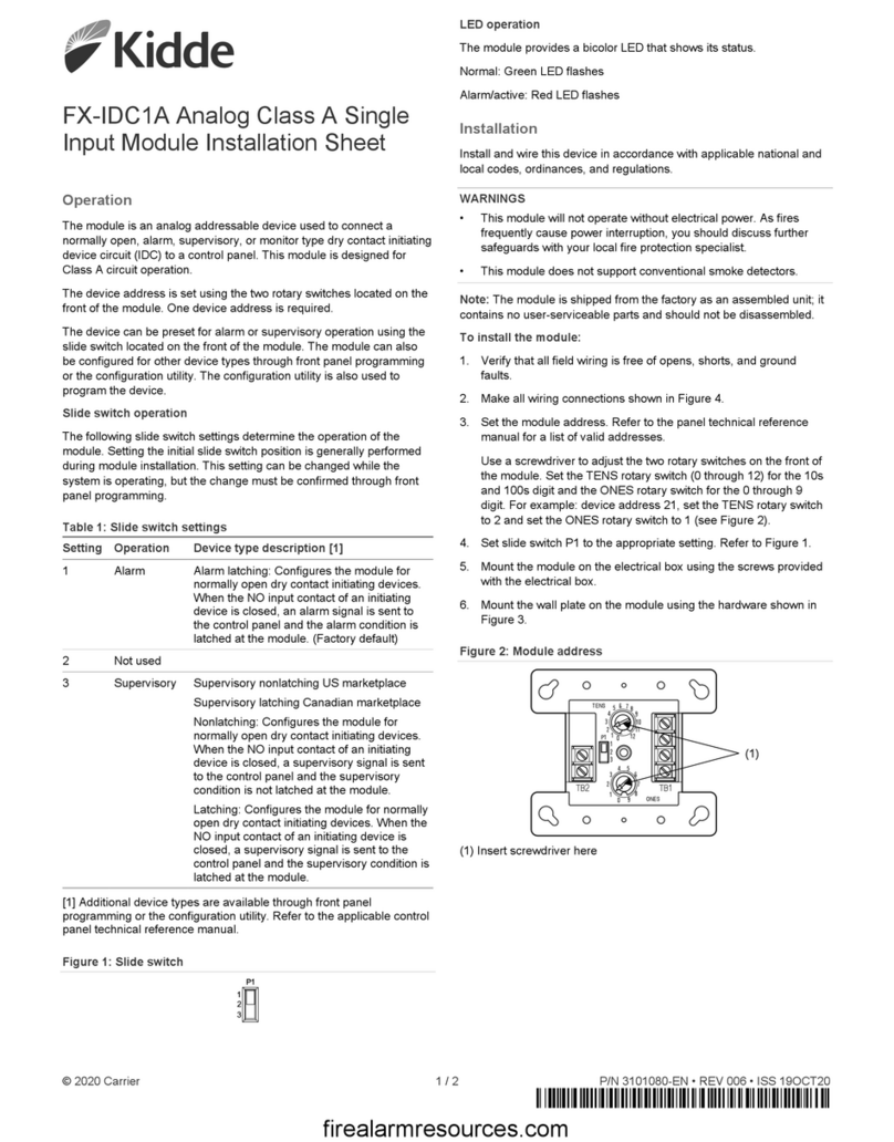
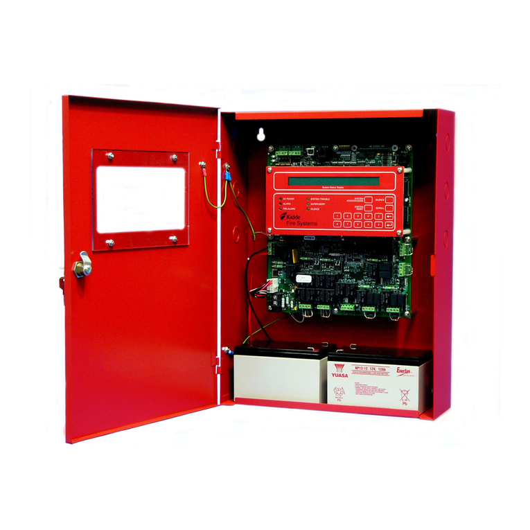
KIDDE AEGIS Operating Instructions
Normal Standby Operation
Green AC ON LED lit steadily
All other LED’s OFF
Alarm Condition
These actions occur when any cross-zone or single zone
alarm condition is reported:
1) Appropriate red alarm LED and SYSTEM ALM LED flashes
2) Buzzer on continuously
3) Signal circuit devices on as programmed
4) Programmed release time delay is activated
5) The programmable relays actuate as configured.
What To Do When an Alarm Occurs
Press the “ACKNOWLEDGE” button to change an alarm LED
from flashing to steady and silence the internal buzzer. It will
be necessary to press the “ACKNOWLEDGE” button more
than once if multiple alarm events have occured.
What To Do If a Supervisory Message Occurs
Press the “ACKNOWLEDGE” button to change a supervisory
LED from flashing. To steady and silence the internal buzzer. It will
be necessary to press the “ACKNOWLEDGE” button more than
once if multiple supervisory events have occurred.
Once the condition is cleared the system must be reset. Follow
reset procedure as described in Alarm Condition instructions.
Trouble Condition
These actions occur when any trouble condition is reported:
1) An appropriate trouble LED flashes.
2) SYSTEM TBL LED flashes.
3) Buzzer pulses.
4) Programmed relay outputs activate.
How to Silence Audible Notification Appliances
Press the “SIGNAL SILENCE” button to de-activate any silenceable
outputs such as notification appliances.
The yellow SIGNAL SILENCED LED will go on steady.
A subsequent press of the “SIGNAL SILENCE” button will re-activate
any outputs that were silenced if no new alarm events have been
reported since the outputs were silenced.
The SIGNAL SILENCED LED will go off.
This toggling capability will remain in effect until the control unit is
reset.
Alarm Reset
Press “SYSTEM RESET”, Panel will return to normal standby operation.
NOTE: If alarms, troubles, or supervisory conditions still remain
on the inputs, the panel will return to that condition.
Supervisory Condition
These actions occur when any supervisory condition is reported:
1) Appropriate SUP# LED flashes.
2) SYSTEM SUP LED flashes.
3) Buzzer pulses.
4) Programmed relay outputs activate.
What To Do When a Trouble Message Occurs
Press the “ACKNOWLEDGE” button to change the trouble LED’s
from flashing to steady and silence the internal buzzer. It will be
necessary to press the “ACKNOWLEDGE” button more than once
if multiple trouble events have occured.
Trouble indicators clear when condition is resolved.
Switch Functions
Local Service Company
NAME:______________________________
ADDRESS:___________________________
__________________________
TEL NO:_____________________________
Maintenance & Testing
Warning!
Be sure that all suppression systems are disconnected according
to the manufacturer’s instructions before you perform
any maintenance or testing for this control unit.
Standby-Battery Replacement
System Maintenance & Testing
Refer to Installation, Operation, & Maintenance Manual,
P/N 06-236716-001, for recommended testing and
maintenance procedures.
Part No. 06-236719-002 Rev AA
Refer to Installation, Operation, & Maintenance Manual,
P/N 06-236716-001, to test the standby batteries. Replace
batteries every three years, or more frequently as recommended
by the manufacturer.
Operation of Abort
Discharge is aborted only when an Alarm is from a detector and
Abort is activated during programmed release time delay. Abort
sequence is dependent on programming.
1) Press “ABORT” switch if installed.
2) ABORT LED will go on.
3) Release countdown will abort as programmed.
4) Release “ABORT” switch. LED will go off.
5) Countdown will continue as programmed.
NOTE: A “MANUAL RELEASE” will override an “ABORT” switch.
1) Press “OUTPUT DISABLE” button to disable outputs, SYSTEM
SUP LED flashes.
2) Subsequent button press enables outputs, SYSTEM SUP LED
goes off.
Lamp Test
1) Press the “ACKNOWLEDGE” button continuously for a minimum
of 5 seconds.
2) All LED’s and the 7 segment displays will turn on.
3) Release “ACKNOWLEDGE” button to end test.
FRAME AND POST ADJACENT TO PANEL
