Neptune Challenge AR Rower User manual
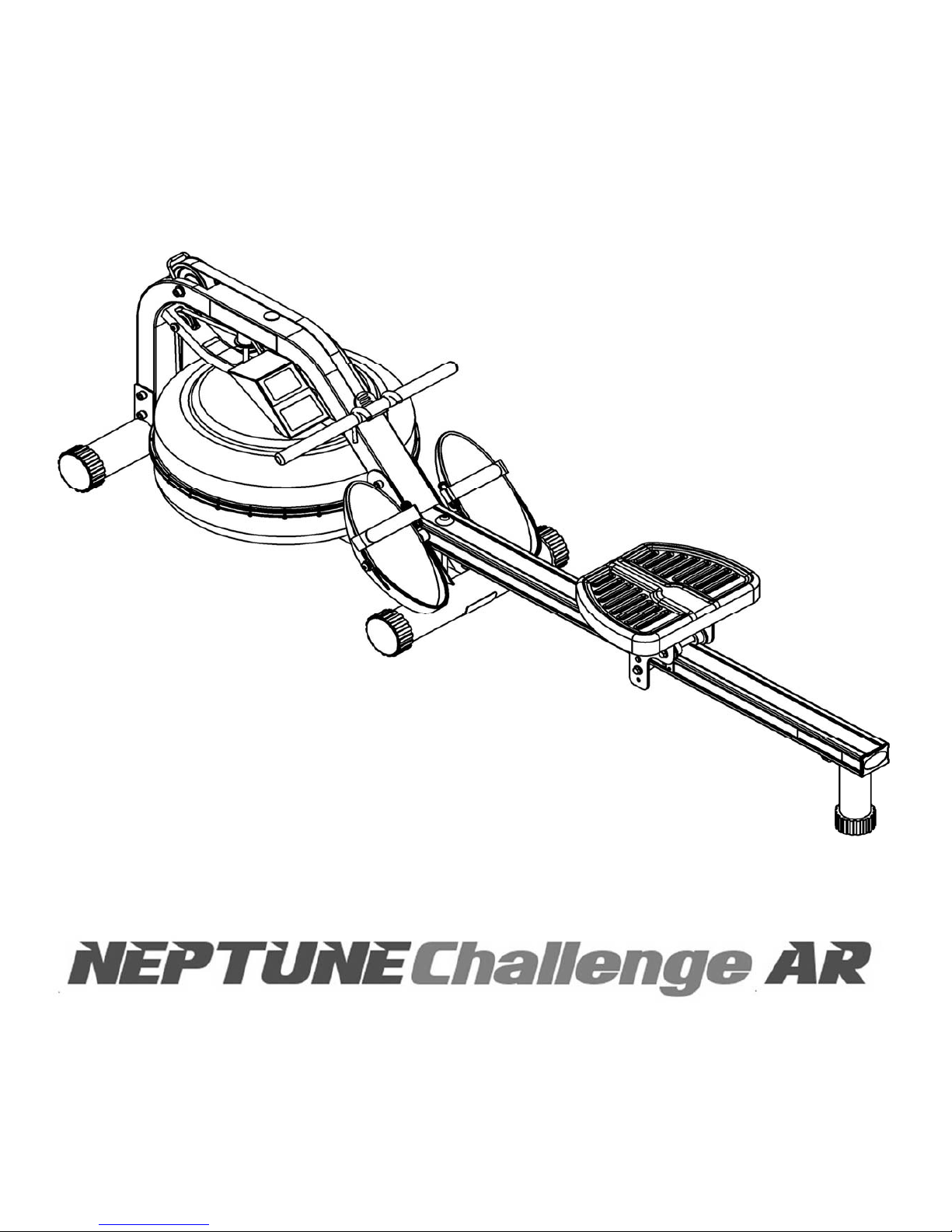
Owners Manual

2
Contents
Neptune Challenge AR Rower Box Contents
Assembly Instructions
Fine Tuning Neptune Challenge AR
Adjustable Resistance (AR) Tank
Note on Filling the AR Tank
Tank Filling and Water Treatment
Removing/Changing Tank Water
The Neptune Challenge AR Rower Computer
How to Row?
How Often?
Detaching the Rower Belt
Retching the Rower Belt
Removing the Bungee Shock Cord
Replacing the Bungee Shock Cord
Troubleshooting
4
6
8
9
10
11
12
13
14
14
15
15
16
17
18

3
Training with the Neptune Challenge AR Rower
1. As with any piece of fitness equipment, consult a physician before be-
ginning your Neptune Challenge AR Rower exercise program.
2. Follow instructions provided in this manual for correct foot position
and basic rowing techniques.
1. The Neptune ChallengeAR Rower can stand vertically for storage.
Make sure a secure location is chosen, such as the corner of a room or
against a wall.
2. Keep hands and fingers away from moving parts, as indicated by the
warning sticker on the mainframe of your machine.
CAUTION

4
2
3
9 19
20
21
18
17
22
23
24 25 26
27 28
29
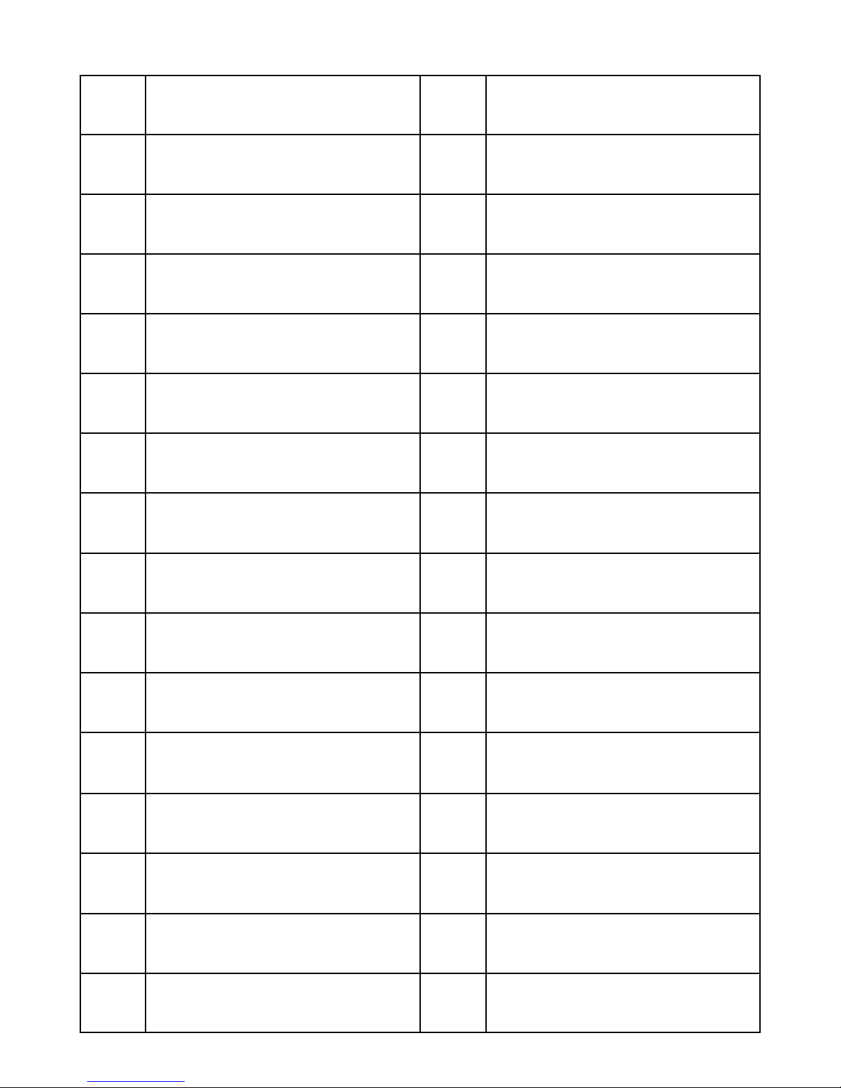
Neptune Challenge AR Rower Box Contents
5
Item Description Item Description
1 Main Frame 16 Footstrap (2)
2 Rower Seat 17 Rear Leg (1)
3 Seat Rail (boxed separately) 18 75x50 Rubber End Cap (1)
4 M10x180mm Bolt (1) 19 M10x25 Rear Leg Bolt (1)
5 M10 Plastic Dome Washer (1) 20 Rear Rubber Bumpstop (1)
6 M10 Nylock Nut (2) 21 M6x10mm Bumpstop Screws (2)
7 M10 Washer (1) 22 Seat Rail Internal Support Brack-
et (1)
8 M10x95mm Bolt (1) 23 Siphon
9 11x21x2T Washer (3) 24 Multi-Tool (1)
10 Footplate (2) 25 6mm Allen Key (2)
11 12mmx388mm Footplate Shaft
(1) 26 8mm Allen Key (1)
12 Nylon Footplate Spacer (2) 27 2x AA Batteries
13 17mmx1.5Tx110 Internal Spacer
(1) 28 4x Water Treatment Tablet
14 M8x15mm Bolt (2) 29 Owners Manual
15 M8 Washer (2)
Table of contents
Popular Fitness Equipment manuals by other brands


G-FITNESS
G-FITNESS AIR ROWER user manual

CAPITAL SPORTS
CAPITAL SPORTS Dominate Edition 10028796 manual

Martin System
Martin System TT4FK user guide

CIRCLE FITNESS
CIRCLE FITNESS E7 owner's manual

G-FITNESS
G-FITNESS TZ-6017 user manual

Accelerated Care Plus
Accelerated Care Plus OMNISTIM FX2 CYCLE/WALK user manual


