Neptune NXP-M User manual

Neptune stepper motor-driven diaphragm pump
NXP-M and NXP-P
Operating instructions
Read the operating manual!
The user is responsible for installation and operation related mistakes!

Table of Contents 3
Subject to technical changes.
Neptune stepper motor-driven diaphragm pump NXP-M and NXP-P Operating instructions
Table of Contents
1 Notes for the Reader ..........................................................4
1.1 General non-discrimination......................................................4
1.2 Explanation of the signal words ................................................4
1.3 Explanation of the warning signs ..............................................4
1.4 Identification of warnings.........................................................4
1.5 Instruction for action identification ...........................................4
2 Safety .................................................................................5
2.1 General warnings.....................................................................5
2.2 Hazards due to non-compliance with the safety instructions .....6
2.3 Working in a safety-conscious manner .....................................6
2.4 Personal protective equipment.................................................6
2.5 Personnel qualification.............................................................6
3 Intended use ...................................................................... 8
3.1 Notes on product warranty .......................................................8
3.2 Intended purpose.....................................................................8
3.3 Device revision ........................................................................8
3.4 Principles ................................................................................8
3.5 Prohibited dosing media...........................................................8
3.6 Foreseeable misuse.................................................................8
4 Product description .........................................................10
4.1 Properties..............................................................................10
4.2 Scope of delivery ...................................................................10
4.3 Structure of the dosing pump .................................................10
4.4 Function description ..............................................................11
4.5 Rating plate ...........................................................................11
4.6 Conveying characteristics ......................................................12
5 Technical data..................................................................13
5.1 Delivery capacity data............................................................13
5.2 Operating conditions and limits ..............................................13
5.3 Electrical specifications .........................................................14
5.4 Other data .............................................................................14
6 Dimensions ......................................................................15
6.1 NXP-M/P 68 through 285 .......................................................15
6.2 NXP-M/P 375, 540, and 810...................................................16
7 Installing the Dosing Pump.............................................. 17
7.1 Set up information .................................................................17
7.2 Installation examples .............................................................17
8 Hydraulic installations..................................................... 18
8.1 Design of the system..............................................................18
8.2 System piping........................................................................19
8.3 Aligning the dosing head ........................................................19
8.4 Hydraulic connections............................................................19
8.5 Connecting a leakage drain....................................................21
8.6 Connecting the dosing head venting facility ............................21
8.7 Hydraulic accessories ............................................................21
9 Electrical installation.......................................................24
9.1 Principles ..............................................................................24
9.2 Description of connection sockets ..........................................25
10 Control..............................................................................27
10.1 Operating elements of the control NXP-M .............................27
10.2 Operating elements of the control NXP-P ..............................27
10.3 Password protection ............................................................28
11 Operation..........................................................................30
11.1 Commissioning the dosing pump..........................................30
11.2 NXP-P: Operating modes......................................................31
11.3 External On / Off via Release input ........................................32
11.4 Decommissioning the dosing pump......................................33
11.5 Shutting down in an emergency ...........................................33
11.6 Storage ...............................................................................33
11.7 Transportation......................................................................33
11.8 Disposal of old equipment....................................................33
12 Maintenance ....................................................................34
12.1 Maintenance intervals..........................................................34
12.2 Tighten up dosing head bolts................................................34
12.3 Change the diaphragm.........................................................35
12.4 Clean suction and discharge valves ......................................35
13 Troubleshooting ...............................................................36
13.1 Type of fault .........................................................................36
14 Spare parts.......................................................................39
14.1 Diaphragm spare parts kits ..................................................39
14.2 Dosing head spare parts kits including valves.......................39
15 Delivery characteristic curves.........................................40
16 Index.................................................................................41

Notes for the Reader
Instruction for action identification
4
Stepper motor-driven diaphragm dosing pump NXP-M and NXP-P Operating instructions
1 Notes for the Reader
These Operating instructions contain information and behaviour rules for
safe and designated operation of the dosing pump NXP-M and NXP-P.
Observe the following principles:
nRead the entire operating manual prior to starting-up the device.
nEnsure that everyone who works with or on the dosing pump has read
the operating instructions and follows them.
nKeep the operating instructions for the entire service life of the dosing
pump.
nPass on the operating instructions to any subsequent owner of the
dosing pump.
1.1 General non-discrimination
In this operating manual, only the male gender is used where grammar
allows gender allocation. The purpose of this is to make the text easy to
read. Men and women are always referred to equally. We would like to
ask female readers for understanding of this text simplification.
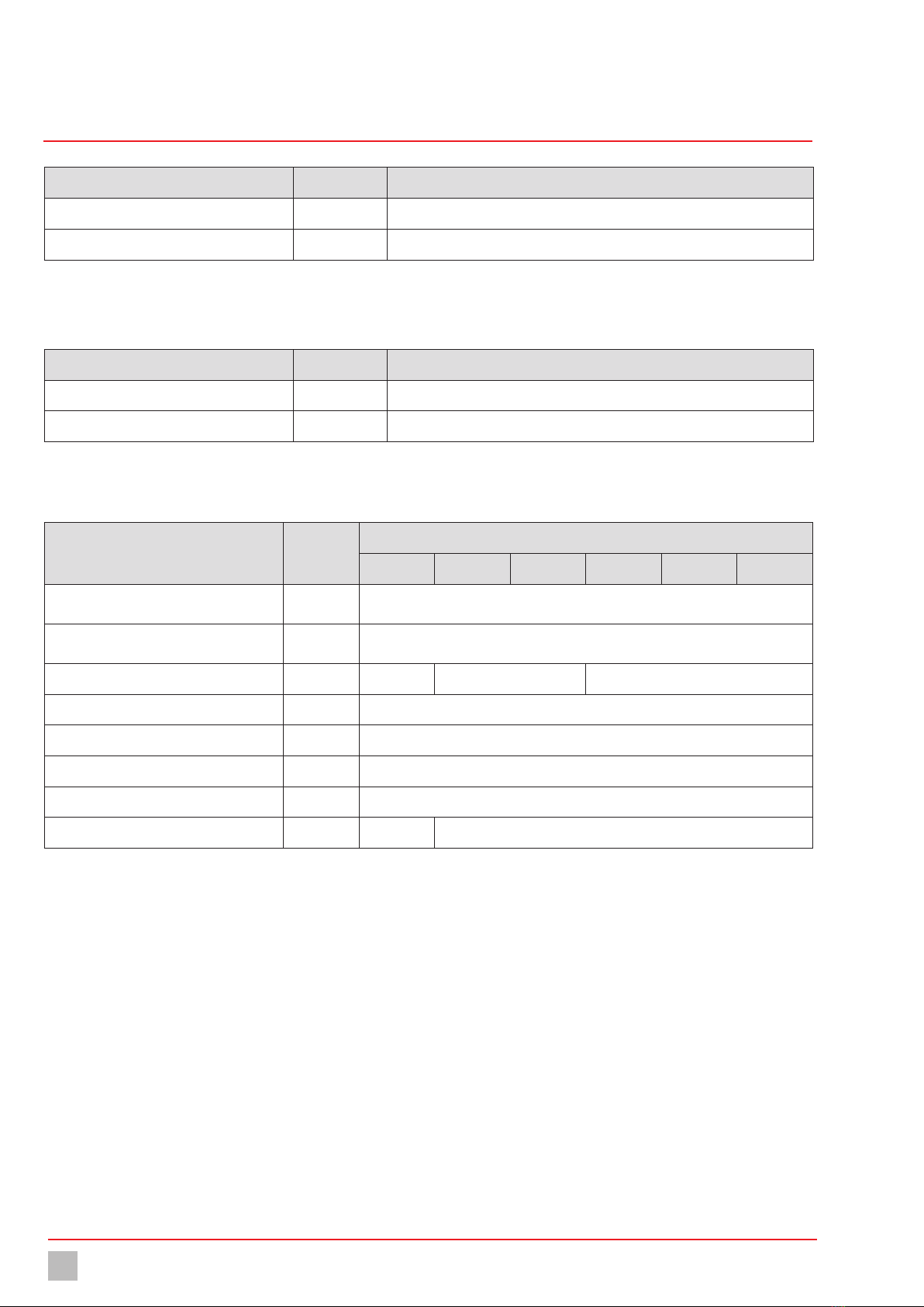
1.2 Explanation of the signal words
Different signal words in combination with warning signs are used in this
operating manual. Signal words illustrate the gravity of possible injuries if
the risk is ignored:
Signal word Meaning
DANGER Refers to imminent danger. Ignoring this sign may
lead to death or the most serious injuries.
WARNING
Refers to a potentially hazardous situation.
Failure to follow this instruction may lead to death
or severe injuries.
CAUTION
Refers to a potentially hazardous situation.
Failure to follow this instruction may lead to
minor injury or damage to property.
NOTE Refers to a danger which, if ignored, may lead to
risk to the machine and its function.
Table 1: Explanation of the signal words
1.3 Explanation of the warning signs
Warning signs represent the type and source of a danger:
Warning sign Type of danger
Danger point
Danger from electrical voltage
Danger from corrosive substances
Danger from potentially-explosive substances
Danger from automatic startup
Danger of damage to machine or functional
influences
Table 2: Explanation of the warning signs
1.4 Identification of warnings
Warnings are intended to help you recognise risks and avoid negative
consequences.
This is how warnings are identified:
Warning sign SIGNAL WORD
Description of danger.
Consequences if ignored.
ðThe arrow signals a safety precaution to be taken to eliminate
the danger.
1.5 Instruction for action identification
This is how pre-conditions for action are identified:
üPre-condition for action which must be met before taking action.
@A resource such as a tool or auxiliary materials required to perform
the operating instructions.
This is how instructions for action are identified:
èSeparate step with no follow-up action.
1. First step in a series of steps.
2. Second step in a series of steps.
4Result of the above action.
üAction completed, aim achieved.

Safety
General warnings 5
Subject to technical changes.
Stepper motor-driven diaphragm dosing pump NXP-M and NXP-P Operating instructions
2 Safety
2.1 General warnings
The following warnings are intended to help you to eliminate the dangers
that can arise while handling the dosing pump. Risk prevention measures
always apply regardless of any specific action.
Safety instructions warning against risks arising from specific activities
or situations can be found in the respective sub-chapters.
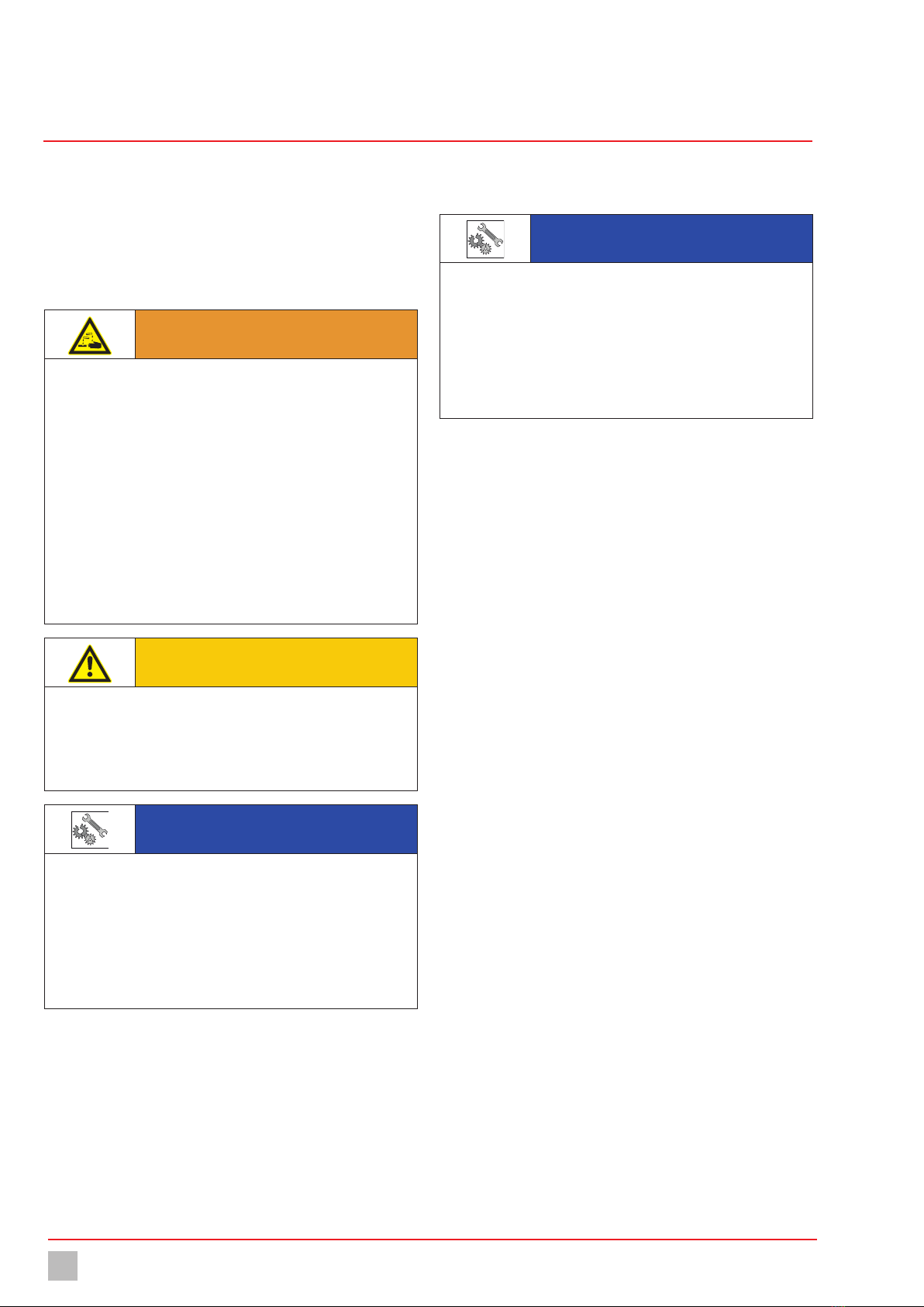
DANGER
Mortal danger from electric shock!
Wrongly connected or located cables or damaged ones can injure you.
ðConnect the device only to a SCHUKO socket outlet protected by a
ground fault circuit interrupter (GFCI).
ðReplace damaged cables without delay.
ðDo not use extension cables.
ðDo not bury cables.
ðSecure cables to avoid being damaged by other equipment.
DANGER
Danger to life through explosions!
The use of dosing pumps without ATEX certification in a potentially
explosive atmospheres can result in potentially-fatal explosions.
ðNever use the dosing pump in potentially explosive areas.
WARNING
Danger from unsuitable materials
The materials of the dosing pump and hydraulic parts of the system
must be suitable for the dosing medium that is used. Should this not
be the case, the dosing media may leak.
ðMake sure that the materials you are using are suitable for the
dosing medium.
ðMake sure that the lubricants, adhesives, sealants, etc. that you
use are suitable for the dosing medium.
WARNING
Caustic burns or other burns through dosing media!
While working on the dosing head, valves and connections, you may
come into contact with dosing media.
ðUse sufficient personal protective equipment.
ðRinse the dosing pump with a liquid (e.g. water) which does not
pose any risk. Ensure that the liquid is compatible with the dosing
medium.
ðRelease pressure in hydraulic parts.
ðNever look into open ends of plugged pipelines and valves.
WARNING
Danger of automatic start up!
After connecting the mains supply, residual dosing media in the
dosing head can spray out.
ðBefore connecting the mains supply, connect the dosing lines.
ðCheck that all the screw connections have been tightened
correctly and are leak-proof.
CAUTION
Danger when changing the dosing medium.
Changing the dosing media can provoke unexpected reactions,
damage to property and injury.
ðClean the dosing pump and the system parts in contact with the
media thoroughly before changing the dosing medium.
CAUTION
Increased risk of accidents due to insufficient qualifica-
tion of personnel!
Dosing pumps and their accessories may only be installed, operated
and maintained by personnel with sufficient qualifications. Insufficient
qualification will increase the risk of accidents.
ðEnsure that all action is taken only by personnel with sufficient and
corresponding qualifications.
ðPrevent access to the system for unauthorised persons.
Safety
Personnel qualification
6
Stepper motor-driven diaphragm dosing pump NXP-M and NXP-P Operating instructions
2.2 Hazards due to non-compliance with the safety
instructions
Failure to follow the safety instructions may endanger not only persons,
but also the environment and the device.
The specific consequences can be:
nfailure of vital functions of the dosing pump and the system,
nfailure of required maintenance and repair methods,
ndanger for individuals through dangerous dosing media,
ndanger to the environment caused by substances leaking from the
system.
2.3 Working in a safety-conscious manner
Besides the safety instructions specified in this operating manual, further
safety rules apply and must be followed:
naccident prevention regulations,
nsafety and operating provisions,
nsafety provisions for handling dangerous substances (mostly the
safety data sheets to dosing media),
nenvironmental protection provisions,
napplicable standards and legislation.
2.4 Personal protective equipment
Based on the degree of risk posed by the dosing medium and the type of
work you are carrying out, you must use corresponding protective
equipment. Read the Accident Prevention Regulations and the Safety
Data Sheets to the dosing media find out what protective equipment you
need.
You will require the minimum of the following personal protective
equipment:
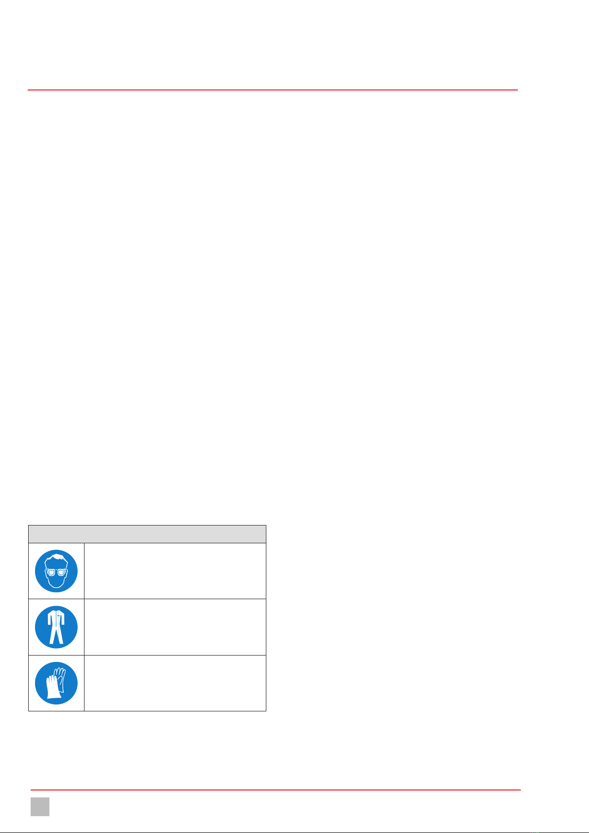
Personal protective equipment required
Protective goggles
Protective clothing
Protective gloves
Table 3: Personal protective equipment required
Wear the following personal protective equipment when performing the
following tasks:
ncommissioning,
nworking on the dosing pump while running,
nshutdown,
nmaintenance work,
ndisposal.
2.5 Personnel qualification
Any personnel who work on the dosing pump must have appropriate
special knowledge and skills.
Anybody who works on the dosing pump must meet the conditions below:
nattendance at all the training courses offered by the owner,
npersonal suitability for the respective activity,
nsufficient qualification for the respective activity,
ntraining in handling of the dosing pump,
nknowledge of safety equipment and the way this equipment functions,
nknowledge of this operating manual, particularly of safety instructions
and sections relevant for the activity,
nknowledge of fundamental regulations regarding health and safety
and accident prevention.
All persons must generally have the following minimum qualification:
ntraining as specialists to carry out work on the dosing pump
unsupervised,
nsufficient training that they can work on the dosing pump under the
supervision and guidance of a trained specialist.
Safety
Personnel qualification 7
Subject to technical changes.
Stepper motor-driven diaphragm dosing pump NXP-M and NXP-P Operating instructions
These operating instructions differentiate between these user groups:
2.5.1 Specialist staff
Thanks to their professional training, knowledge, experience and
knowledge of the relevant specifications, specialist staff are able to
perform the job allocated to them and recognise and/or eliminate any
possible dangers by themselves.
2.5.2 Trained persons
Trained persons have received training from the operator about the tasks
they are to perform and about the dangers stemming from improper
behaviour.
In the table below you can check what qualifications are the pre-condi-
tion for the respective tasks. Only people with appropriate qualifications
are allowed to perform these tasks!
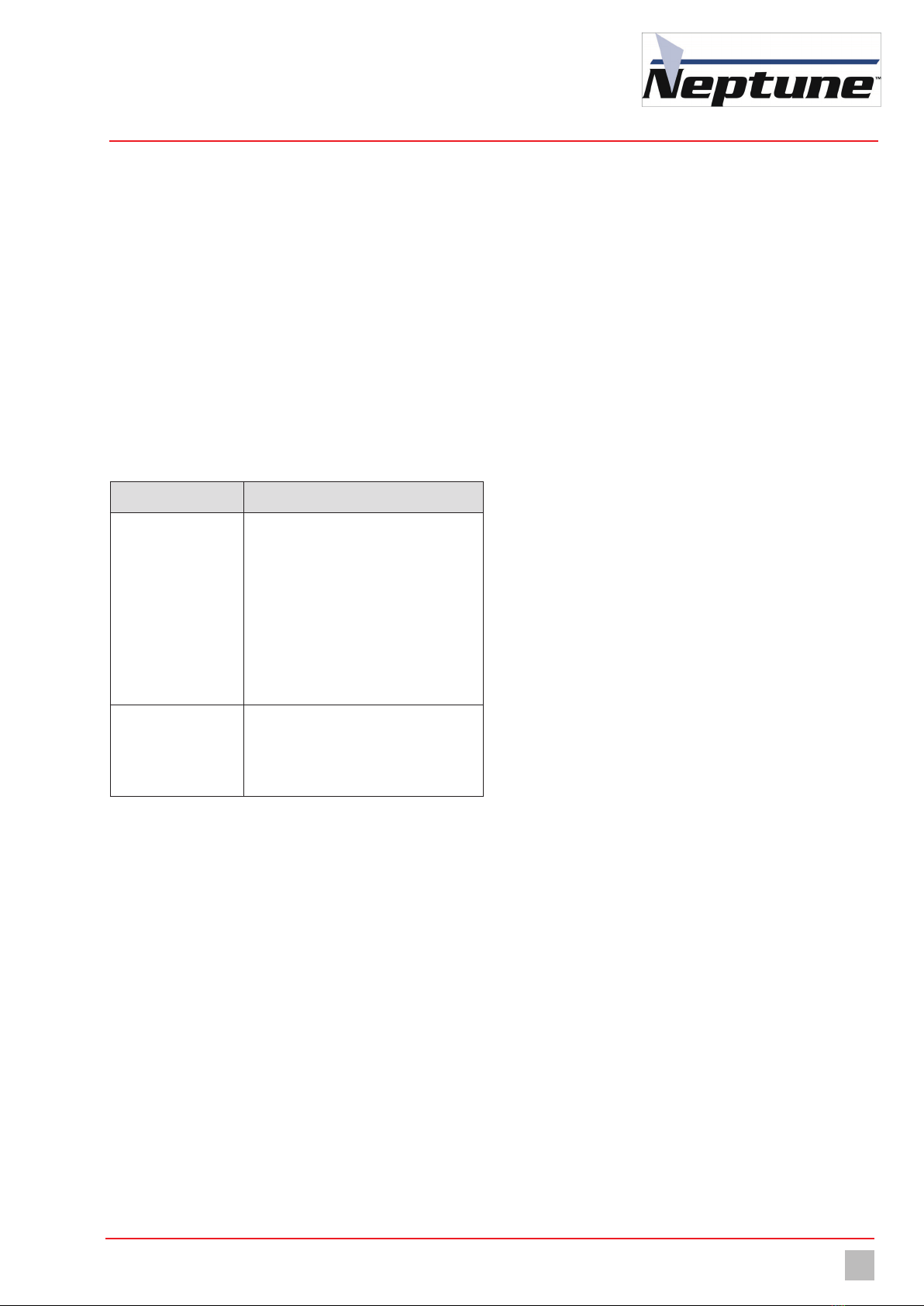
Qualification Activities
Specialist staff nAssembly
nHydraulic installations
nElectrical installation
nMaintenance
nRepairs
nCommissioning
nTaking out of operation
nDisposal
nFault rectification
Trained persons nStorage
nTransportation
nControl
nFault rectification
Table 4: Personnel qualification

Intended use
Foreseeable misuse
8
Stepper motor-driven diaphragm dosing pump NXP-M and NXP-P Operating instructions
3 Intended use
3.1 Notes on product warranty
Any non-designated use of the product can compromise its function or
intended protection. This leads to invalidation of any warranty claims!
Please note that liability is on the side of the user in the following cases:
nThe dosing pump is operated in a manner which is not consistent with
these operating instructions, particularly the safety and handling
instructions and the chapter 3 “Intended use“ on page 8.
nIf people operate the product who are not adequately qualified to carry
out their respective activities.
nNo original spare parts or accessories of Neptune are used.
nUnauthorised changes are made to the device by the user.
nThe user uses different dosing media than those indicated in the
order.
nThe user does not use dosing media under the conditions agreed with
the manufacturer such as modified concentration, density, tempera-
ture, contamination, etc.
3.2 Intended purpose
The dosing pump NXP-M and NXP-P is intended for the following
purpose: the conveying and dosing of liquids.
3.3 Device revision
This operating manual applies to the following devices:
Device Month / year of
manufacture
Firmware
NXP-M 08/2016 onwards
NXP-P 08/2016 onwards From 01:59
Table 5: Device revision
3.4 Principles
nBefore delivery, the manufacturer inspected the dosing pump and
operated it under specific conditions (with a specific dosing medium
with a specific density and temperature, with specific pipe dimen-
sions, etc.) Since these conditions differ at every location of usage,
the delivery capacity of the dosing pump should be measured by
gauging it at the operating company's installation. For details on the
approximate values and the capacity of the dosing pump, refer to the
chapter 15 “Delivery characteristic curves“ on page 40.
nComply with the information regarding the operating and environmen-
tal conditions (see chapter 5 “Technical data“ on page 13).
nAny restrictions regarding the viscosity, temperature and density of
dosing media must be followed. You must only use dosing media at
temperatures above freezing point or below the boiling point of the
respective medium.
nThe materials of the dosing pump and hydraulic parts of the system
must be suitable for the dosing medium that is used. In this connec-
tion, note that the resistance of these components can change in
dependence on the temperature of the media and the operating
pressure.
i
Information on the suitability of materials combined with
different dosing media can be found in the Compatibility Chart
of Neptune.
The information in this resistance list is based on information
from the material manufacturers and on expertise obtained by
Neptune from handling the materials.
As the durability of the materials depends on many factors,
this list only constitutes initial guidance on selecting material.
In all cases, test the equipment with the chemicals you use
under operating conditions.
nThe dosing pump is not intended for outdoor use unless appropriate
protective measures have been taken.
nAvoid leaks of liquids and dust into the casing and avoid direct
exposure to sunlight.
nYou must never operate dosing pumps in a potentially explosive
atmosphere if they do not have corresponding nameplates or an
appropriate EU Declaration of Conformity for potentially explosive
atmospheres.
3.5 Prohibited dosing media
The dosing pump must not be used for these media and substances:
nGaseous media,
nradioactive media,
nsolid substances,
ncombustible media,
nall other media that are not suitable for delivery using this dosing
pump.
3.6 Foreseeable misuse
Below, there is information about the applications of the dosing pump or
associated equipment that are not considered to be intended use. This
section is intended to allow you to detect possible misuse in advance and
to avoid it.

Intended use
Foreseeable misuse 9
Subject to technical changes.
Stepper motor-driven diaphragm dosing pump NXP-M and NXP-P Operating instructions
Foreseeable misuse is assigned to the individual stages of the product
lifetime:
3.6.1 Incorrt assembly
nUnstable or unsuitable bracket
nDosing pump bolted wrongly or loosely
3.6.2 Incorrect hydraulic installation
nSuction and pressure lines dimensioned incorrectly
nUnsuitable connection of the pipes due to wrong material or
unsuitable connections.
nSuction and pressure lines mixed-up
nDamage to threads due to them being tightened too much
nBending of pipelines
nNo free return flow of the pressure relief valve
nExcessive demand due to the pressure differences between the
suction and discharge valves
nThrough-suction at installation without back-pressure valves
nDamage due to undamped acceleration mass forces
nExceeding the admissible pressure on the suction and discharge sides
nUsing damaged parts
3.6.3 Incorrect electrical installation
nConnecting the mains voltage without a protective earth
nUnsecured mains or one that does not conform to standards
nNot possible to immediately or easily disconnect the power supply
nWrong connecting cables for mains voltage
nDosing pump accessories connected to wrong sockets
nDiaphragm monitoring not connected or defective
nProtective earth removed
3.6.4 Incorrect start-up
nStart-up with damaged system
nShut-off valves closed at commissioning
nClosed suction or pressure line, e.g. due to blockages
nPersonnel was not informed before the start-up
nSystem was recommissioned after maintenance without all the
protective equipment and fixtures, etc. being reconnected
nInadequate protective clothing or none at all
3.6.5 Incorrect operation
nProtective equipment not functioning correctly or dismantled
nModification of the dosing pump without authority
nIgnoring operational disturbances
nElimination of operational disturbances by personnel without
adequate qualifications
nDeposits in the dosing head due to inadequate purging, particularly
with suspensions
nBridging the external fuse
nOperation made more difficult due to inadequate lighting or machines
that are difficult to access
nOperation not possible due to dirty or illegible display of the dosing
pump
nDelivery of dosing media for which the system is not designed
nDelivery of particulate or contaminated dosing media
nInadequate protective clothing or none at all
3.6.6 Incorrect maintenance
nCarrying out maintenance during ongoing operation
nCarrying out work that is not described in the operating manual
nNo adequate or regular inspection of correct functioning
nNo replacement of damaged parts or cables with inadequate
insulation
nNo securing against reactivation during maintenance work
nUsing cleaning materials that can cause reactions with the dosing
media
nInadequate cleaning of the system
nUnsuitable purging medium
nUnsuitable cleaning materials
nDetergents left in system parts
nUsing unsuitable cleaning equipment
nUsing the wrong spares or lubricants
nContaminating the dosing medium with lubricant
nInstalling spare parts without following the instructions in the
operating manual
nBlocking venting orifices
nPulling off sections of the plant
nContamination at installation without a dirt trap
nMixing up the valves
nMixing up the sensor lines
nNot reconnecting all the lines
nDamaging or not installing all the seals
nNot renewing seals
nNot paying attention to safety data sheets
nInadequate protective clothing or none at all
3.6.7 Incorrect decommissioning
nNot completely removing the dosing medium
nDismantling lines while the dosing pump is running
nDevice not disconnected from the power supply
nUsing the wrong dismantling tools
nInadequate protective clothing or none at all
3.6.8 Incorrect disposal
nIncorrect disposal of dosing media, operating resources and other
materials
nNo labelling of hazardous substances

Product description
Structure of the dosing pump
10
Stepper motor-driven diaphragm dosing pump NXP-M and NXP-P Operating instructions
4 Product description
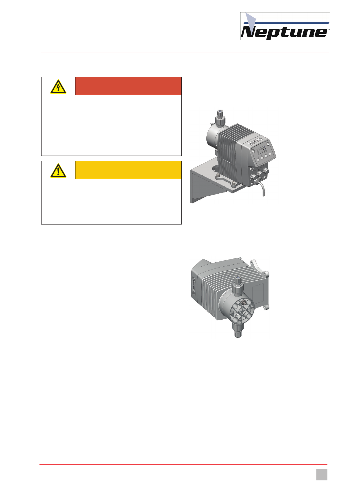
4.1 Properties
The NXP-M and NXP-P is a stepper motor-driven diaphragm dosing pump
that is used when precise dosing results are required.
They are characterized by the following properties:
nOutput range from 0.68 – 8.10 gph, up to 290 psig
nPower supply 110—240 V, 50/60 Hz, IP65, 25 W
nMicroprocessor-controlled drive
nIntegrated dosing head ventilation (only NXP-M/P 68 through 285 with
plastic dosing head)
nSuitable for wall and floor mounting
nMaterial finishes PVC, PP, PVDF and stainless steel
nRelease input for external start/stop
Also with NXP-P:
nPulse input (increase and reduction)
nLevel input with early warning and main alarm
nStroke frequency can be precisely adjusted via the keyboard
nGraphic display
nCalculation wizard for pulse operation available online
4.2 Scope of delivery
Please compare the delivery note with the scope of delivery.The
following items are part of the scope of delivery:
nDosing pump NXP-M and NXP-P,
nOne set each of hose clamping connections for the suction and
discharge sides for hoses with diameters of 4/6 mm, 1/4 x 3/8” (made
of PVC, PP and PVDF),
nCovering caps electrical connections:
1 for NXP-M
3 for NXP-P,
nConductive rubber band for electrical contacts:
1 for NXP-M (in connection port 1)
2 for NXP-P (in connection ports 1 and 3),
nMains cable,
nOperating instructions,
nInspection report and test certificate (optional),
nAccessory kit (optional).
4.3 Structure of the dosing pump
4.3.1 General Overview
a
b
c
Fig. 1: General Overview
No. Description
1Dosing head
2Drive unit
3Control box
Table 6: General Overview
4.3.2 Dosing head
a
c
d
b
Fig. 2: Dosing head
No. Description
1Valve and connection on the discharge side
2Integrated dosing head ventilation (only NXP-M/P 68 through 285
with plastic dosing head)
3Arrow indicating the direction of throughflow of the dosing
medium (plastic version only)
4Valve and connection on the suction side
Table 7: Dosing head
Product description
Rating plate 11
Subject to technical changes.
Stepper motor-driven diaphragm dosing pump NXP-M and NXP-P Operating instructions
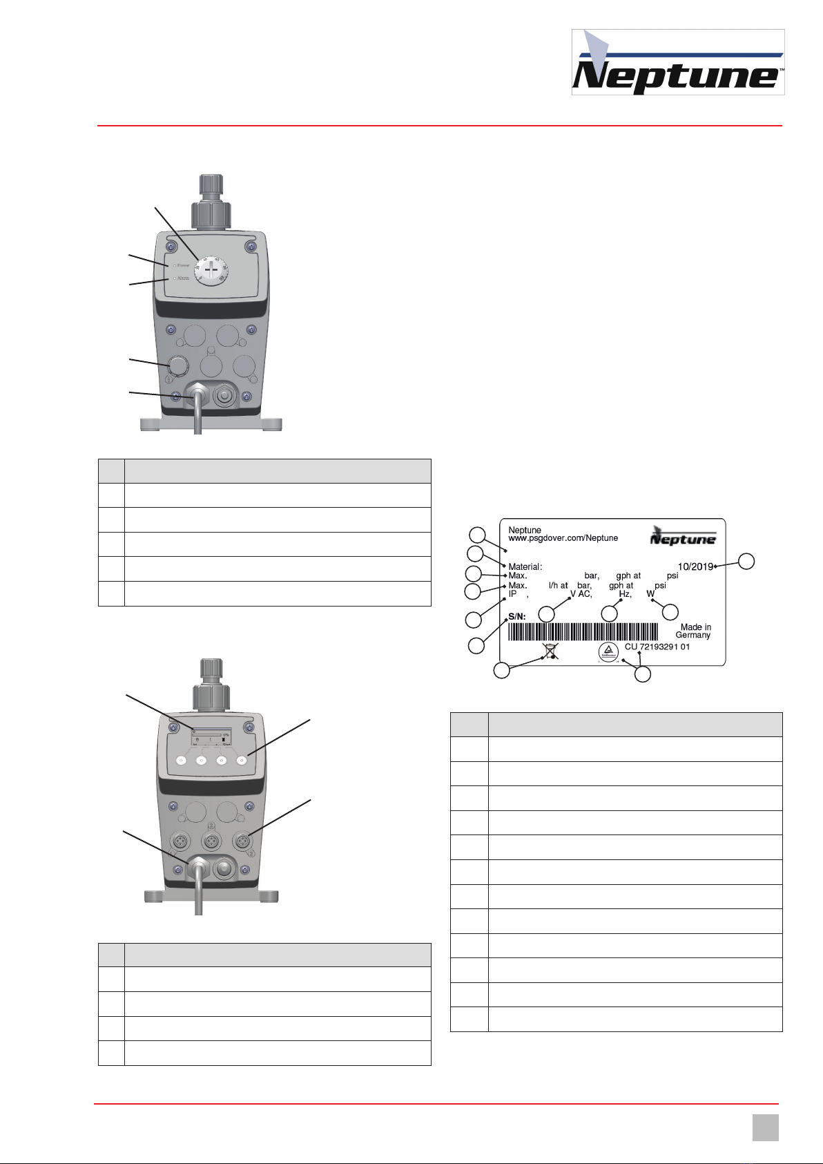
4.3.3 Control element of the NXP-M
Fig. 3: Dosing pump control NXP-M
No. Description
1Stroke frequency setting
2Power LED
3Alarm LED
4Release input for external start/stop
5Mains cable for power supply
Table 8: Designation of components
4.3.4 Control element of the NXP-P
a
b
d
c
Fig. 4: Dosing pump control NXP-P
No. Description
1Graphic display
2Multifunction keys on the contol unit for operator inputs
3Connection ports for external operation
4Mains cable for power supply
Table 9: Designation of components
4.4 Function description
Dosing pumps are positive displacement pumps. They are used if
precisely defined delivery of a medium is necessary.A constant volume
per stroke or time is delivered.
The system delivers or meters the dosing medium by means of a
repeated sequence of suction strokes followed by pressure strokes. This
results in a pulsing flow.
If the dosing pump is in the suction stroke phase, the diaphragm is pulled
into the rear final position. Due to the resulting vacuum in the dosing
head, the discharge valve closes, the suction valve opens and dosing
medium flows from the suction line into the dosing head.
If the dosing pump is in the pressure stroke phase, the diaphragm is
moved into the front final position. Due to the pressure in the dosing head,
the suction valve closes and the dosing medium flows through the
discharge valve from the dosing head into the pressurised pipe.
4.5 Rating plate
There is information on the equipment about safety or the product's way
of functioning. The information must stay legible for the duration of the
service life of the product.
Fig. 5: Rating plate NXP-M and NXP-P
No. Description
1Product, type, nominal size
2Maximum delivery capacity at average pressure
3Maximum delivery capacity at maximum pressure
4Protection class
5Voltage supply
6CSA certificate
7WEEE label
8 Frequency
9Power consumption
10 Serial number
11 Month / year of manufacture
12 Material of the dosing head / seals
Table 10: Rating plate
a
b
c
d
e
NXP 11
10
2
1
45
6
7
89
12
3

Product description
Conveying characteristics
12
Stepper motor-driven diaphragm dosing pump NXP-M and NXP-P Operating instructions
4.6 Conveying characteristics
The design of the dosing pump enables it to perform the pressure and suction stroke at different speeds. For low supply rates, for example, the dosing
pump performs the suction stroke at the maximum speed and adjusts the speed of the pressure stroke to match the desired supply rate.This produces
a constant supply stream, which gives you a low-pulsation, smooth dosing.
Fig. 6:
Settings
100 % delivery rate Time
50 % delivery rate Time
10 % delivery rate Time
Pressure stroke
Suction stroke
Selecting available dosing programs

Technical data
Operating conditions and limits 13
Subject to technical changes.
Stepper motor-driven diaphragm dosing pump NXP-M and NXP-P Operating instructions
5 Technical data
5.1 Delivery capacity data
Please note that some of this data only represents guide values. The actual capacity of a dosing pump depends on various factors. For approximate
values of the delivery capacity at different pressures, refer to chapter 15 “Delivery characteristic curves“ on page 40.
Information Value
NXP-M and NXP-P Size
M68/P68 M140/P140 M285/P285 M375/P375 M540/P540 M810/P810
Delivery capacity at max. backpressure
gph 0.68 1.4 2.85 3.75 5.4 8.10
ml/stroke 0.22 0.57 1.19 1.52 2.27 3.41
Max. delivery pressure psig 290 (232*) 232 145 88 74 44
Delivery capacity at average backpressure
gph 0.7 1.59 2.98 3.88 5.6 8.2
ml/stroke 0.28 0.63 1.26 1.60 2.36 3.44
Average delivery pressure psig 145 116 72 44 36 22
Max. stroke frequency min-1 150
Table 11: Output data
* with a PVC design.
5.2 Operating conditions and limits
Information Value NXP-M and NXP-P Size
Approved ambient temperature °F 41 – 113 (with PVC components 41 – 104)*
Relative humidity %max. 90
Max. sound pressure level dB(A) 51 – 56
Max. supply pressure mbar 800
Viscosity limits mPa∙s 300** / 1000***
Adjustable dosing range %0 – 100
Table 12: Operating conditions and limits
* Use of the dosing pump at ambient temperatures below 41 °F must be checked individually. In such cases, please contact the manufacturer.
** With a viscosity of ~300 mPa∙s and above, you must use spring-loaded valves.
*** If the viscosity of the medium is larger than 1000 mPa·s, the use of the dosing pump must be checked individually. In such cases, please contact the
manufacturer.
5.2.1 Approved media temperature
Information Value NXP-M and NXP-P (all sizes)
Dosing head made of PVC °F 32 – 95
Dosing head made of PP °F 32 – 140
Table 13: Approved media temperature
Technical data
Other data
14
Stepper motor-driven diaphragm dosing pump NXP-M and NXP-P Operating instructions
Information Value NXP-M and NXP-P (all sizes)
Dosing head made of PVDF °F 32 – 176
Dosing head made of stainless steel (1.4571) °F 32 – 176
Table 13: Approved media temperature
5.3 Electrical specifications
Information Value NXP-M and NXP-P (all sizes)
Voltage supply 110 – 240 V AC, -10% / +5%, 50/60 Hz
Power consumption W 25
Table 14: Electrical specifications
5.4 Other data
Information Value
NXP-M and NXP-P Size
M68/P68 M140/P140 M285/P285 M375/P375 M540/P540 M810/P810
Weight (with dosing head made of PVC, PP,
PVDF) Ib 4.85 approx.
Weight (with dosing head made of stainless
steel (1.4571)) Ib 7.27 approx.
Diameter of diaphragm in 1.299 1.535 2.125
Electrical cable ft 5.9 ft (with mains plug)
Protection class IP65 (with covering caps on the connections)
Insulation class F
Valve connection G5/8 male
Valve size DN3 DN4
Table 15: Other data

15
Subject to technical changes.
Neptune stepper motor-driven diaphragm pump NXP-M and NXP-P Operating instructions
Dimensions
6 Dimensions
6.1 NXP-M/P 68 through 285
~3~1.7
~ 2.3
~ 7.09
4.72 L
L
~ 10.23
~8.07
3.94
4.57
Ø
3.15
2.76
Ø
0.26
Fig. 7: Dimensioned drawing of NXP-M/P 68 through 285 with dosing head made of PVC, PP or PVDF (all dimensions in inch)
~9.33"
~7.95"
~ 3.15"
~ 0.67"
LL
~ 4.72"
~7.08"
~ 2.32"
2.76"
Ø
0.25
3.94"
4.57"
Ø
3.15"
Fig. 8: Dimensioned drawing of NXP-M/P 68 through 285 with dosing head made of stainless steel (1.4571) (all dimensions in inch)
Hose clamp connector Material Scale Nominal width L
NXP-M68 and NXP-P68
PVC / PP / PVDF 4/6 mm DN4 31
Stainless steel 4/6 mm DN4 50
NXP-M/P 140 and 285
PVC / PP / PVDF
4/6 mm DN4 31
1/4x3/8" 1/4" 34
Stainless steel (1.4571) / PVDF 4/6 mm DN4 50

16
Neptune stepper motor-driven diaphragm pump NXP-M and NXP-P Operating instructions
Dimensions
6.2 NXP-M/P 375, 540, and 810
~ 3.31~ 0.69
LL
~ 2.1
~ 7.12
2.76
Ø
0.26
Ø
3.31
3.94
4.57
~ 9.33
~ 7.93
Fig. 9: Dimensioned drawing of NXP-M/P 375,540, and 810 with dosing head made of PVC, PP, PVDF or stainless steel (1.4571) (all dimensions in mm)
Hose clamp connector Material Scale Nominal width L
NXP-M/P 375,540, and 810
PVC / PP / PVDF
4/6 mm DN4 31
1/4x3/8" 1/4" 34
Stainless steel (1.4571) / PVDF 4/6 mm DN4 50
~ 5.2 (stainless steel)
Installing the Dosing Pump
Installation examples 17
Subject to technical changes.
Stepper motor-driven diaphragm dosing pump NXP-M and NXP-P Operating instructions
7 Installing the Dosing Pump
DANGER
Mortal danger from electric shock!
Electrically conductive liquid can enter pump housings, cable screw
connections and mains connectors.
ðMake sure that all protective measures comply at least with the
requirements of protection class IP65.
ðAlways set up the dosing pump such that water cannot enter the
housing.
CAUTION
Danger of personal injury and material damage!
A dosing pump that is difficult to access represents a danger due to
incorrect operation and faulty maintenance.
ðInstall the dosing pump such that it is accessible at all times.
Especially the oil level glass, the oil inlet and the oil drain.
7.1 Set up information
When installing, follow the basic principles below:
nThe valves must be vertical: Discharge valve at top, suction valve at
bottom. in this connection, pay attention to the arrow on the dosing
head. The dosing head must be aligned such that the arrow points
vertically upwards.
nYou should install the dosing pump at a convenient height for
operation.
nIt must not be installed under the ceiling.
nThe frame of foundation for fixing the dosing pump must not be
subjected to jolts. The pump must be vibration-free and stable.
nThere must be enough free space in the area of the dosing head and
the suction and discharge valves for these parts to be easily
dismantled if required. The entire space requirement for installation
and maintenance is approximately 1 m².
nThe distance from the sides of the dosing pump to the wall or other
dosing pumps or equipment must be at least 3 cm. There must be a
guaranteed flow of circulating air.
nThe maximum ambient temperature must be complied with, see
chapter 5.2 “Operating conditions and limits“ on page 13. If
necessary, radiant heat from surrounding equipment must be
screened.
nAvoid exposure to direct sunlight.
nThe dosing pump is not intended for use out of doors unless
appropriate protective measures have been taken to prevent dust and
water from entering the housing.
nFor the dimensions of the fastening holes, refer to chapter 6
“Dimensions“ on page 15.
nThe tightening torque for the fastening bolts is 1.5 – 2 Nm.
7.2 Installation examples
7.2.1 Installation on a wall console
Fig. 10: Installation on a wall console
To reduce the structure-borne noise, the dosing pump is bolted to the wall
bracket using rubber elements. The materials necessary for this are
included with the wall bracket.
7.2.2 Installation on the wall
Fig. 11: Installation on the wall
The dosing pump can be mounted to the floor or directly to the wall
without the need for additional elements. Turn the dosing head appropri-
ately to ensure the flow direction of the medium through the dosing head.
Hydraulic installations
Design of the system
18
Stepper motor-driven diaphragm dosing pump NXP-M and NXP-P Operating instructions
8 Hydraulic installations
In this chapter, you will find information about the hydraulic parts of a
system that you should install or that can install additionally. In many
cases, you must install hydraulic accessories to be able to use all the
functions that the dosing pump offers, to guarantee functional safety or to
achieve a high level of dosing precision.
WARNING
Caustic burns or other burns through dosing media!
A diaphragm rupture, blocked pressure lines or the use of material not
suitable for the dosing medium can result in the discharge of dosing
medium. Depending on the type and hazardousness of the dosing
medium, this can result in injury.
ðWear the recommended personal protective equipment.
ðMake sure that the materials you are using are suitable for the
dosing medium.
ðMake sure that the lubricants, adhesives, sealants, etc. that you
use are suitable for the dosing medium.
ðInstall a leakage drain.
ðInstall pressure relief valves.
CAUTION
Danger of personal injury and material damage!
High peak pressures can lead to piping vibrating and cause them to
snap. This can result in injury from piping or escaping dosing media.
ðInstall pulsation dampeners.
NOTE
Damage to drives due to overloading
The pressure conditions between the suction and discharge sides
must be balanced; otherwise, overloading can result. This can lead to
uncontrolled dosing processes, damage to the piping and to the
dosing pump.
ðEnsure that the pressure on the discharge side is at least 15 psig
than on the suction side.
NOTE
Locking of threads
Stainless steel and plastic parts (particularly those made of PVC) that
are bolted together in a detachable connection (e.g. the dosing head
and the valves) can lock. This makes them difficult to release.
ðBefore bolting, grease the corresponding parts with a lubricant
(e.g. PTFE spray). Ensure that the lubricant is compatible with the
dosing medium.
8.1 Design of the system
nThe dosing pumps technical data (see chapter 5 “Technical data“ on
page 13) must be taken into account and the plant s layout must be
set up appropriately (e.g. pressure loss when rating the lines with
regard to their nominal diameter and length).
nThe entire system and its integrated dosing pump must be designed
in such a way that an escaping dosing medium (due to the failure of
wearing parts such as the diaphragm, or burst hoses) does not lead to
permanent damage to system parts or the premises.
nThe leakage opening of the dosing head must be visible so that you
can detect a diaphragm rupture. It must be possible for the outflow
from the leakage drain to be on a free downwards gradient.
nIf you use hazardous dosing media, the installation must be designed
such that no disproportionately high consequential damages arise
due to dosing media escaping.
nTo avoid dosing errors after the end of the process, the dosing pump
must be locked hydraulically.
nTo allow you to easily inspect the pressure conditions in the system,
you should provide connections for pressure gauges close to the
suction and discharge valves.

Hydraulic installations
Hydraulic connections 19
Subject to technical changes.
Stepper motor-driven diaphragm dosing pump NXP-M and NXP-P Operating instructions
8.2 System piping
nThe system piping must not exert any force on the connections and
valves of the dosing pump.
nThis means that steel piping should be connected to the dosing pump
by means of flexible pipe sections.
nThe nominal diameters of the pipework and the installed fittings
should be rated the same as or greater than the nominal diameters of
the dosing pump's suction and discharge valves.
nThe suction line should be kept as short as possible.
nYou should avoid intertwined hoses.
nAvoid loops, since air bubbles can collect.
8.3 Aligning the dosing head
a
b
c
Fig. 12: Aligning the dosing head
When connecting the dosing lines to the dosing pump, you must observe
the direction of through-flow (see arrow 2). The dosing head must be
aligned vertically. The alignment can be changed in 90° intervals.
The suction valve (3) must always point downwards. Accordingly, arrow
(2) and pressure valve (1) always point upwards. This is irrespective of the
positioning of the dosing head to the drive.
8.4 Hydraulic connections
8.4.1 Connecting hose clips
Choose the hose connection according to the condition of the hose
(material, inner diameter, wall thickness) in order to ensure maximum
pressure resistance.
8.4.1.1 Size 4/6
a
b
c
d
e
a
b
c
d
e
4/6 6/9
Fig. 13: Hose clips 4/6 and 6/9 (internal and external diameters in mm)
Perform the following working steps:
1. Cut the hose (1) to the appropriate length neatly and at an exact right
angle.
2. Place a gasket that is suitable for the dosing medium between the
connection (5) and the valve.
3. Screw the connecting piece to the dosing pump's valve using the
union nut (2).
4. Thread the union nut (3) and the clamping ring (4) onto the hose.
5. Plug the hose all the way in to the grommet of connection piece.
6. Push the clamping ring onto the grommet of connection piece and
screw it to the union nut.
7. Carry out the same procedure with the connection to the dosing
pump's other valve.
üHose clip connected.

Hydraulic installations
Hydraulic connections
20
Stepper motor-driven diaphragm dosing pump NXP-M and NXP-P Operating instructions
8.4.1.2 Size 6/12
a
b
c
d
Fig. 14: Hose clip 6/12 (internal and external diameter in mm)
Size 6/12 hose clips only have a union nut. It clamps the hose onto the
grommet of the connection piece and at the same time fastens on the
dosing pump's valve.
Perform the following working steps:
1. Cut the hose (1) to the appropriate length neatly and at an exact right
angle.
2. Place a gasket that is suitable for the dosing medium between the
connection (4) and the valve.
3. Push the union nut (2) and the cutting ring (3) over the hose. Press
the end of the hose onto the grommet of connection piece.You can do
this more easily by moistening the end of the hose on the inside or
applying some lubricant to the grommet in the cone area. You should
push at least two thirds of the hose onto the grommet of the
connection piece.
4. Push the cutting ring over the hose into the cone area on the
grommet of connection piece.
5. Screw the union nut onto the valve of the dosing pump.
üHose clip connected.
8.4.2 Making the glue-in connection
a
b
Fig. 15: Glue-in connection
Perform the following working steps:
1. Cut the PVC tube to length.
2. Push the union nut (1) onto the tube.
3. Stick the bonded coupling sleeve (2) to the tube (follow the
instructions of the adhesive manufacturer).
4. Screw the union nut onto the valve of the dosing pump. Use a gasket
that is suitable for the dosing medium.
üGlue-in connection made.
8.4.3 Making the cemented connection
a
b
Fig. 16: Cemented connection
Perform the following working steps:
1. Cut the tube to length.
2. Cut the thread (2) onto the end of the tube.
3. Push the union nut (1) onto the tube.
4. Seal the thread.When choosing your sealing material, take into
account its resistance to material, temperature and pressure.
5. Screw the union nut onto the valve of the dosing pump. Use a gasket
that is suitable for the dosing medium.
üCemented connection made.
i
Under normal conditions, you only need to screw the hydraulic
connections finger-tight. However, due to the material settling,
the pre-tension of the screw connection can slacken. This
means that you must re-tighten the screw connection before
carrying out commissioning.
This manual suits for next models
1
Table of contents
Other Neptune Water Pump manuals

Neptune
Neptune NPVS150 Assembly instructions

Neptune
Neptune 500 Series Instruction manual

Neptune
Neptune 7000 Series Owner's manual

Neptune
Neptune MP7100 Owner's manual

Neptune
Neptune VTF Installation instructions

Neptune
Neptune 560 Series Instruction Manual

Neptune
Neptune Apex WAV User manual

Neptune
Neptune NSP-M User manual
Popular Water Pump manuals by other brands


VS
VS ZJ Series Operating instruction

Flo King
Flo King Permacore Reusable Carbon Bag Disassembly. & Cleaning Instructions

BRINKMANN PUMPS
BRINKMANN PUMPS SBF550 operating instructions

Milton Roy
Milton Roy PRIMEROYAL instruction manual

Tesla
Tesla 4OL Installation and operating instructions

Crane
Crane Barnes SGV 2 HP Installation and operation manual


