nerian SP1 User manual

SP1 Stereo Vision System
User Manual
(v1.0) August 28, 2015
VISION TECHNOLOGIES
Dr. Konstantin Schauwecker
Nerian Vision Technologies
Gotenstr. 9
70771 Leinfelden-Echterdingen
Germany
Email: [email protected]

Contents
1 Functionality Overview 3
2 Included Parts 3
3 General Specifications 3
3.1 HardwareDetails .......................... 3
3.2 StereoMatching........................... 3
3.3 ImageRectification......................... 4
4 Mechanical Specifications 4
4.1 Dimensions ............................. 4
4.2 Mounting .............................. 4
5 Physical Interfaces 6
6 Hardware Setup 7
6.1 ConnectingtheSP1......................... 7
6.2 SupportedCameras......................... 7
6.3 CameraAlignment ......................... 8
6.4 ExternalTrigger........................... 8
7 Processing Results 9
7.1 RectifiedImages........................... 9
7.2 DisparityMaps ........................... 9
8 Configuration 11
8.1 SystemStatus............................ 11
8.2 Preview ............................... 12
8.3 Processing Settings . . . . . . . . . . . . . . . . . . . . . . . . . 14
8.4 Cameras............................... 15
8.4.1 Camera Selection . . . . . . . . . . . . . . . . . . . . . . 15
8.4.2 Camera Settings . . . . . . . . . . . . . . . . . . . . . . 16
8.4.3 Recommended Settings for Point Grey Cameras . . . . . 17
8.4.4 Recommended Settings for IDS Cameras . . . . . . . . . 17
8.5 Trigger................................ 18
8.6 CameraCalibration......................... 18
8.6.1 Calibration Board . . . . . . . . . . . . . . . . . . . . . . 18
8.6.2 Recording Calibration Frames . . . . . . . . . . . . . . . 20
8.6.3 Performing Calibration . . . . . . . . . . . . . . . . . . . 21
8.7 Reviewing Calibration Results . . . . . . . . . . . . . . . . . . . 21
8.8 NetworkSettings .......................... 24
8.9 Maintenance............................. 24
1

9 API Usage Information 25
9.1 General Information . . . . . . . . . . . . . . . . . . . . . . . . 25
9.2 ImageTransfer Example . . . . . . . . . . . . . . . . . . . . . . 26
9.3 AsyncTransfer Example . . . . . . . . . . . . . . . . . . . . . . 28
9.4 3DReconstruction ......................... 29
10 SpCom Sample Application 29
11 Support 31
12 Warranty Information 31
13 Open Source Information 32
2

3 GENERAL SPECIFICATIONS
1 Functionality Overview
The SP1 stereo vision system is a stand-alone processing system for performing
stereo matching in real time. It is connected to two industrial USB cameras
that provide input image data. The SP1 correlates the images of both cameras
and produces a disparity map, which is transmitted through gigabit ethernet.
The disparity map describes a mapping of image points from the left camera
image to corresponding image points in the right camera image. With this
information it is possible to reconstruct the 3D location of the corresponding
scene points.
2 Included Parts
When ordering a new SP1 from Nerian Vision Technologies, the package should
include the following parts:
•SP1 stereo vision system
•5 V DC power adapter
•4 stickable rubber pads (not included for surface mountable version)
•Manual
If any of the listed parts is missing in your delivery, please contact our
support personnel.
3 General Specifications
3.1 Hardware Details
Power consumption: < 4 W
Power supply: 5 V DC
Dimensions: 105 x 76 x 36 mm
Weight: 0.25 kg
I/O: USB 2.0 host, gigabit ethernet, 2x trigger out
Max. USB power: 500 mA
3.2 Stereo Matching
Stereo algorithm: Semi-Global Matching (SGM)
Disparity range: 112 pixels
Processing rate: 30 Hz
Sub-pixel resolution: 4 bits (1/16 pixel)
Supported image size: 640 ×480 pixels
Post-processing: Consisteny check, uniqueness check,
gap interpolation, noise reduction
3

3.3 Image Rectification 4 MECHANICAL SPECIFICATIONS
-
75
?
6
36
(a)
-
75
?
6
36
(b)
-
105
?
6
36
(c)
-
105
?
6
75
(d)
Figure 1: (a) Front, (b) rear, (c) side and (d) top view of SP1 with dimensions
in millimeters.
3.3 Image Rectification
Horizontal displacement: −31 to +31 pixels
Vertical displacement: −31 to +31 pixels
Interpolation: Bilinear
4 Mechanical Specifications
4.1 Dimensions
Figures 1a to 1d show the SP1 as seen from front, rear, side and top. The
provided dimensions are measured in millimeters.
4.2 Mounting
The SP1 is optionally available in a surface mountable version. This version
features a mounting plate that is attached to the bottom side of the housing.
The four through holes on the mounting plate can be used for mounting the
SP1 onto a flat surface. The dimensions of this mounting plate are shown in
millimeters in Figure 3. The through holes are compatible to screws with an
M4 ISO metric thread.
4

4.2 Mounting 4 MECHANICAL SPECIFICATIONS
Figure 2: SP1 with attached mounting plate.
Figure 3: Mounting plate dimensions in millimeters.
5

5 PHYSICAL INTERFACES
-
Power LED
@@
@R
Busy LED AAAA
AU
Trigger port
Ethernet port
USB port
(a)
Power jack
(b)
Figure 4: Interfaces on (a) front and (b) rear housing side.
5 Physical Interfaces
Figures 4a and 4b show the interfaces on the SP1’s front and backside. The
power jack is located on the backside, and it needs to be connected to the
supplied power adapter or an equivalent model. When using an alternative
power supply, please make sure that the voltage is set no higher than 5 V DC,
as otherwise the device might be damaged.
The front side features the following interfaces:
Power LED: Indicates that the device is powered up and running.
Busy LED: Indicates that the device is currently processing incoming input
data.
Trigger port: Port for providing two camera trigger signals. See Section 6.4.
Ethernet port: Port for connecting to a client computer. It is used for de-
livering processing results, and for providing access to the configuration
interface.
USB port: Port for connecting the desired USB cameras through a USB hub.
6

6 HARDWARE SETUP
USB cameras Computer
SP1
USB hub
Ethernet
Figure 5: Example setup for cameras, SP1 and client computer.
6 Hardware Setup
6.1 Connecting the SP1
Figure 5 shows a basic system setup for stereo vision. A client computer that
receives the processing results is connected to the SP1’s ethernet port. Alter-
natively it is possible to connect the SP1 to a switched network. However, you
will have to ensure that the network is capable of handling the high bandwidth
data that is transmitted by the device. The network must support data rates
of at least 25 MB/s.
The cameras are connected to the SP1’s USB port. As the SP1 only features
one USB port, a USB hub is mandatory for making this connection. Please
note that the USB hub usually has to be powered externally, to meet
the power consumption of the cameras.
6.2 Supported Cameras
The SP1 supports the following camera models:
•Point Grey Blackfly; model BFLY-U3-03S2M-CS
•Point Grey Blackfly; model BFLY-U3-13S2M-CS
•Point Grey Chameleon3; model CM3-U3-13S2M-CS
•Point Grey Chameleon3; model CM3-U3-13Y3M-CS
•Point Grey Flea3; model FL3-U3-13E4M-C
•Point Grey Flea3; model FL3-U3-13Y3M-C
•Point Grey Grasshopper3; model GS3-U3-14S5M-C
•Point Grey Grasshopper3; model GS3-U3-15S5M-C
7

6.3 Camera Alignment 6 HARDWARE SETUP
Figure 6: Example for standard epipolar geometry.
•IDS uEye ML; model UI-3240ML-M-GL
•IDS uEye CP; model UI-3140CP-M-GL Rev.2
•IDS uEye CP; model UI-3240CP-M-GL
All cameras must have a gray scale sensor.
6.3 Camera Alignment
Both cameras have to be mounted on a plane with a displacement that is
perpendicular to the cameras’ optical axes. Furthermore, both cameras must
be equipped with lenses that have an identical focal length. This arrangement
is known as the standard epipolar geometry. An example for such a camera
mounting is shown in Figure 6.
The distance between both cameras is referred to as baseline distance. Us-
ing a large baseline distances improves the depth resolution at high distances.
A small baseline distances, on the other hand, allows for the observation of
very close objects. The baseline distance should be adjusted in conjunction
with the lenses’ focal length. An online tool for computing desirable combina-
tions of baseline distance and focal length can be found on the Nerian Vision
Technologies website1.
6.4 External Trigger
For stereo matching it is important that both cameras are synchronized, mean-
ing that both cameras record an image at exactly the same point of time. Many
industrial cameras already feature the ability to synchronize themselves, by
having one camera produce a trigger signal for the respective other camera.
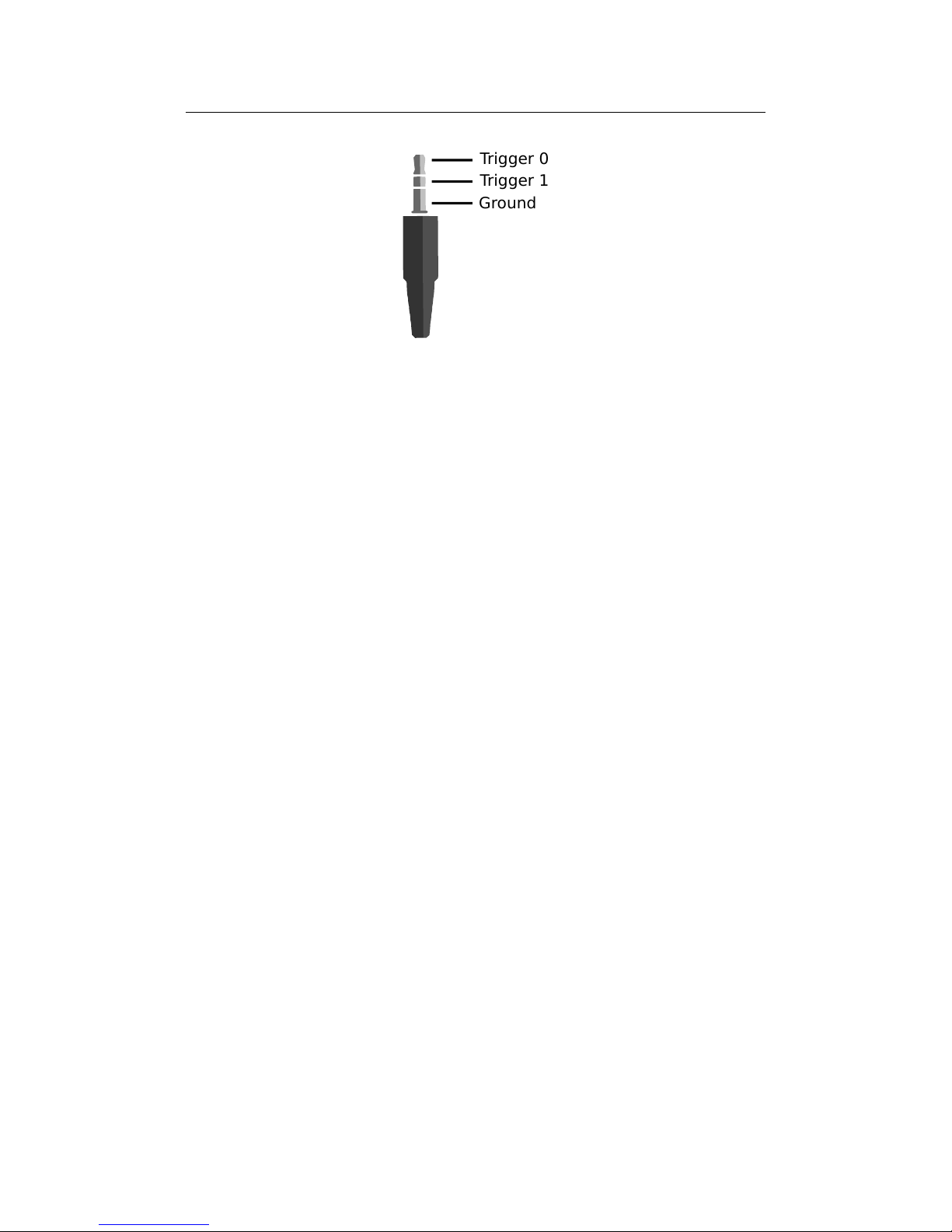
As an alternative, the SP1 can produce up to two trigger signals. The
signals are provided through the trigger port, which can receive a standard
3.5 mm phone connector. The pin assignment for this connector is shown in
Figure 7.
The peak voltage of both trigger signals is at +3.3 V. To protect the trigger
port from short circuits, each signal line is connected through a 220 Ωseries
1http://nerian.com/products/sp1-stereo-vision/calculator/
8
7 PROCESSING RESULTS
Ground
Trigger 0
Trigger 1
Figure 7: Pin assignement for trigger output.
resistor. Trigger frequency and pulse width can be configured through the web
interface (see Section 8.5).
7 Processing Results
7.1 Rectified Images
Even when carefully aligning both cameras, you are unlikely to receive images
that match the expected result form an ideal standard epipolar geometry.
The images will be affected by various distortions that result from errors in
the cameras’ optics and mounting. Therefore, the first processing step that
is performed is an image undistortion operation, which is known as image
rectification.
Image rectification requires precise knowledge of the cameras’ projective
parameters. These can be determined through camera calibration. Please refer
to Section 8.6 for a detailed explanation of the camera calibration process.
Figure 8a shows an example camera image, where the camera was pointed
towards a calibration board. The edges of the board appear slightly bent,
due to radial distortions in the camera’s optics. Figure 8b shows the same
image after image rectification. This time, all edges of the calibration board
are perfectly straight.
When performing stereo matching, the SP1 additionally outputs the rec-
tified left camera image. This allows for a mapping of features in the visible
image to structures in the determined scene depth and vice versa.
7.2 Disparity Maps
The stereo matching results are delivered in the form of a disparity map for
the left camera image. The disparity map assigns each pixel in the left camera
image to a corresponding pixel in the right camera image. Because both im-
ages were previously rectified to match an ideal standard epipolar geometry,
9

7.2 Disparity Maps 7 PROCESSING RESULTS
(a) (b)
Figure 8: Example for (a) unrectified and (b) rectified camera image.
(a) (b)
Figure 9: Example for (a) left camera image and corresponding disparity map.
corresponding pixels should only differ in their horizontal coordinates. The
disparity map thus only has to encode the horizontal coordinate difference.
An example for a left camera image and the corresponding disparity map
are shown in Figure 9a and 9b. Here the disparity map has been color coded,
with blue hues reflecting small disparities, and red hues reflecting large dispar-
ities. The disparity is proportional to the inverse depth of the corresponding
scene point. It is thus possible to transform the disparity map into a set of 3D
points. This can be done at a correct metric scale if the cameras have been
calibrated.
The transformation of a disparity map to a set of 3D points requires knowl-
edge of the disparity-to-depth mapping matrix Q, which is computed during
camera calibration and can be obtained from the review calibration page of the
SP1’s web interface (see Section 8.7). The 3D location x y zTof a point
with image coordinates (u, v)and disparity dcan be reconstructed as follows:
10

8 CONFIGURATION
x
y
z
=1
w·
x0
y0
z0
, with
x0
y0
z0
w
=Q·
u
v
d
1
An efficient implementation of this transformation is provided with the
available API (see Section 9.4).
The SP1 computes disparity maps with a resolution that is below one pixel.
Disparity maps have a bit-depth of 12 bits, with the lower 4 bits of each value
representing the fractional disparity component. It is thus necessary to divide
each value in the disparity map by 16 in order to receive the correct disparity
magnitude.
The SP1 applies several post-processing techniques in order to improve
the quality of the disparity maps. Some of these methods detect erroneous
disparities and mark them as invalid. Invalid disparities are set to 0xFFF,
which is the highest value that can be stored in a 12-bit disparity map. In
Figure 9b invalid disparities have been depicted as black.
8 Configuration
The SP1 is configured through a web interface, which can be reached by en-
tering the IP address of the SP1 in your browser. The default address is
http://192.168.10.10. Please configure the IP address and subnet mask of your
computer appropriately, such that this interface can be reached. If the SP1
has just been plugged in, it will take several seconds before the web interface
is accessible.
For using the web interface you require a browser with support
for HTML 5. Please use a recent version of one of the major browsers, such
as Internet Explorer, Firefox, Chrome or Safari.
8.1 System Status
The first page that you will see when opening the web interface, is the system
status page that is shown in Figure 10. On this page you can find the following
information:
Processing status: Indicates whether the image processing sub-system has
been started. If this is not the case then there might be a problem
accessing the cameras, or another system error might have occurred.
Please consult the system logs in this case. The image processing sub-
system will be started immediately once the cause of error has been
removed (such as connecting the cameras).
SOC temperature: The temperature of the central System-on-Chip (SoC)
that performs all processing tasks. The maximum allowed temperature
11

8.2 Preview 8 CONFIGURATION
Figure 10: Screenshot of configuration status page.
is at 70 ◦C. A green-orange-red color-coding is applied to signal good,
alarming and critical temperatures.
System logs: List of system log messages sorted by time. In regular operation
you will find information on the current system performance. In case of
errors, the system logs will contain a corresponding error message.
8.2 Preview
The preview page, which is shown in Figure 11, provides a live preview of the
currently computed disparity map. Please make sure that your network con-
nection supports the high bandwidth that is required for streaming video data
(see Section 6.1). For using the preview page you require a direct connection
to the SP1. An in-between proxy server or a router that performs network
address translation (NAT) cannot be used.
When opening the preview page, the SP1 stops transferring image data to
any other host. The transfer is continued as soon as the browser window is
closed, the user presses the pause button below the preview area, or if the user
navigates to a different page. Only one open instance of the preview page,
or any other page that is streaming video data to the browser, is allowed at
a time. If attempted to open more than once, only one instance will receive
data.
The preview that is displayed in the browser does not reflect the full qual-
12

8.2 Preview 8 CONFIGURATION
Figure 11: Screenshot of configuration preview page.
ity of the computed disparity map. In particular, sub-pixel accuracy is not
available, and your browser might not be able to display the disparity map at
the full camera frame rate. To receive a full-quality preview, please use the
SpCom sample application, which is described in Section 10.
Different color-coding schemes can be selected through the drop-down list
below the preview area. A color scale is shown to the right, which provides
information on the mapping between colors and disparity values. The possible
color schemes are:
Red / blue: A gradient from red to blue, with red hues corresponding to
high disparities and blue hues corresponding to low disparities. Invalid
disparities are depicted in black.
Rainbow: A rainbow color scheme with low wavelengths corresponding to
high disparities and high wavelengths corresponding to low disparities.
Invalid disparities are depicted in grey.
Raw data: The raw disparity data without color-coding. The pixel inten-
sity matches the integer component of the measured disparity. Invalid
disparities are displayed in light gray.
13

8.3 Processing Settings 8 CONFIGURATION
Figure 12: Screenshot of configuration page for processing settings.
8.3 Processing Settings
The major processing parameters can be changed on the processing settings
page, which is shown in Figure 12. The most relevant option is the operation
mode, which can be set to one of the following values:
Pass through: In this mode the SP1 forwards the imagery of the selected
cameras without modification. This mode is intended for verifying that
both cameras are functioning correctly.
Rectify: In this mode the SP1 transmits the rectified images of both cameras.
This mode is intended for verifying the correctness of image rectification.
Stereo matching: In this mode the SP1 performs stereo matching. It trans-
mits the rectified image of the left camera and the left camera disparity
map.
Please note that for pass through and rectify mode, the the right
image pixels have to be divided by 16, in order to receive the correct
intensities. This is due to the fact that the right image is always transmitted
with a bit depth of 12 bits.
If the operation mode is set to stereo matching, then the behavior of the
image processing algorithms can be controlled through the algorithm settings.
These settings include the following stereo matching parameters:
14

8.4 Cameras 8 CONFIGURATION
Penalty for disparity changes (P1): A penalty that is applied for gradu-
ally changing disparities. A large value causes gradual disparity changes
to occur less frequently, while a small value causes gradual changes to
occur more frequently. This value has to be smaller than P2.
Penalty for disparity discontinuities (P2): A penalty that is applied to
abruptly changing disparities. A large value causes disparity discontinu-
ities to occur less frequently, while a small value causes discontinuities
to occur more frequently. This value has to be greater than P1.
The SP1 implements several methods for post-processing of the computed
disparity map. Each post-processing method can be activated or deactivated
individually. The available methods are:
Mask border pixels: If enabled, this option marks all disparities that are
close to the border of the visible image area as invalid, as they have a high
likelihood of being wrong. This also includes all pixels for which no actual
image data is available due to the image rectification (see Section 7.1).
Consistency check: If enabled, stereo matching is performed in both match-
ing directions, left-to-right and right-to-left. Pixels for which there is no
consistent disparity are marked as invalid. The sensitivity of the consis-
tency check can be controlled through the consistency check sensitivity
slider.
Uniqueness check: If enabled, pixels are marked as invalid if there is no suf-
ficiently unique solution (i.e. the cost function does not have a global
minimum that is significantly lower than all other local minima). The
sensitivity of the uniqueness check can be controlled through the unique-
ness check sensitivity slider.
Gap interpolation: If enabled, then small patches of invalid disparities, which
are caused by either the consistency or the uniqueness check, are filled
through interpolation.
Noise reduction: If enabled, an image filter is applied to the disparity map,
which reduces noise and removes outliers.
8.4 Cameras
8.4.1 Camera Selection
The cameras page that is shown in Figure 13 allows for the selection of a
desired camera pair and the adjustment of their respective parameters. All
detected cameras are listed in the camera selection list. A source is listed
for each camera, which identifies the utilized camera driver. To allow for an
easy evaluation, the SP1 ships with an example stereo sequence on its internal
15

8.4 Cameras 8 CONFIGURATION
Figure 13: Screenshot of configuration page for camera settings.
memory. This example sequence appears as a virtual left and virtual right
camera.
To choose a particular camera, you have to tick either the use as left or
use as right radio button, for selecting the camera as the left or right camera
of the stereo pair. Please note that cameras of different sources cannot be
used together. If one of the virtual example cameras is selected, the example
sequence is replayed in an infinite loop. Due to speed limitations of the internal
memory, the example sequence will not be played at the full frame rate during
the first loop.
8.4.2 Camera Settings
After selecting a camera pair, camera specific settings can be adjusted in the
left camera settings and right camera settings area. The available settings de-
pend on your camera model. Please refer to your camera documentation for
details. Some of the more advanced settings of your camera might not be
available. In this case please use the software provided by the camera manu-
facturer to adjust the desired settings and safe the new camera configuration
to the cameras’ internal memory.
By pressing the reset camera defaults button you can reset the camera’s
settings to the default configuration. This is usually the configuration that
has been written to the camera’s internal memory though the manufacturer
software. If the reset button is pressed, all configuration changes that have not
yet been confirmed through the change button will be reverted.
16

8.4 Cameras 8 CONFIGURATION
The SP1 offers the functionality to synchronize parameters that are other-
wise automatically adjusted by each camera. For example, each camera might
control its shutter time through an auto shutter algorithm. The SP1 can syn-
chronize such auto-adjusted parameters by setting the parameters of the left
camera to always match the respective parameters of the right camera.
If this functionality is desired, the mode for the particular feature has to
be set to synchronize to left camera in the right camera settings, and to auto
in the left camera settings. In this case, the SP1 will query the settings of the
left camera and adjust the right camera’s settings accordingly.
8.4.3 Recommended Settings for Point Grey Cameras
When using Point Grey USB cameras we recommend that you use the following
settings:
•Enable external trigger and select the desired trigger source.
•If the cameras are connected to the SP1’s trigger port, set the trigger
polarity to active high. Otherwise set the polarity according to your
trigger source.
•Set the trigger mode to 0or 14. Always use mode 14 if the internal
camera frame rate is not significantly higher than the trigger frequency.
•For the left camera, set the mode of exposure, sharpness, shutter and
gain to auto.
•For the right camera, set the mode of exposure, sharpness, shutter and
gain to synchronize to left camera.
8.4.4 Recommended Settings for IDS Cameras
When using cameras from IDS Imaging we recommend that you use the fol-
lowing settings:
•If the cameras shall be triggered by the SP1 trigger output:
–Due to voltage levels, the SP1 trigger output needs to be connected
to a camera GPIO pin, rather than the trigger input.
–The connected GPIO pin needs to be selected as trigger source.
–The trigger mode shall be set to hardware trigger, rising edge.
•Set the camera frame rate to at least twice the trigger frequency.
•For the left camera, set the mode of gain, exposure / shutter and black
level to auto.
•For the right camera, set the mode of gain, exposure / shutter and black
level to synchronize to left camera.
17

8.5 Trigger 8 CONFIGURATION
Figure 14: Screenshot of configuration page for trigger settings.
8.5 Trigger
The trigger page that is shown in Figure 14 allows for adjusting the external
trigger settings. As described in Section 6.4, the SP1 features a trigger port
that provides access to up to two trigger signals. The two trigger signals,
trigger 0 and trigger 1, can be enabled or disabled by selecting the respective
check boxes.
For trigger 0 it is possible to select a frequency between 6 and 50 Hz and
an arbitrary pulse width in milliseconds. The polarity of the generated trigger
signal is active high.
The signal trigger 1 can only be enabled if trigger 0 is also enabled. The
frequency is forced to the same value as trigger 0. However, it is possible to
specify a time offset, which is the delay from a rising edge of trigger 0 to a
rising edge of trigger 1. Furthermore, trigger 1 can have a pulse width that
differs from trigger 0.
8.6 Camera Calibration
8.6.1 Calibration Board
The calibrate cameras page, which is shown in Figure 15, enables the calibration
of the stereo camera pair. You require a calibration board, which is a flat panel
with a visible calibration pattern on one side. The pattern that is used by the
SP1 consists of an asymmetric grid of black circles on a white background, as
shown in Figure 16.
The pattern can be downloaded directly from the calibration page. Simply
select the desired paper size in the calibration board drop-down list, and click
the download link. Even if you already have a calibration board, make sure
to always select the correct board size before starting the calibration process.
Otherwise the calibration results cannot be used for 3D reconstruction with a
18

8.6 Camera Calibration 8 CONFIGURATION
Figure 15: Screenshot of configuration page for camera calibration.
Size: 4 x 11; Circle spacing: 2.0 cm; Circle diameter: 1.5 cm; 5 cm
2 in
nerian.com
Figure 16: Calibration board used by SP1.
19
Table of contents
Popular Magnifier manuals by other brands


National Geographic
National Geographic 91-21001 operating instructions

Freedom Scientific
Freedom Scientific RUBY 10 DIRECTIONS FOR SETUP AND USE

Eschenbach
Eschenbach menas ZOOM user manual

IrisVision
IrisVision Inspire user guide

Eschenbach
Eschenbach Makrolux 143611 user manual

Quicklook
Quicklook Zoom user manual