Neslab HX Series User manual

Installation, Operation,Installation, Operation,
Installation, Operation,Installation, Operation,
Installation, Operation,
and Maintenance Manand Maintenance Man
and Maintenance Manand Maintenance Man
and Maintenance Manualual
ualual
ual
HX AnalogHX Analog
HX AnalogHX Analog
HX Analog
RecirRecir
RecirRecir
Recirculating Chillerculating Chiller
culating Chillerculating Chiller
culating Chiller
NESLABManualP/N002023
Rev.02/25/92

- 1 -
HX Analog RecirHX Analog Recir
HX Analog RecirHX Analog Recir
HX Analog Recirculating Chillerculating Chiller
culating Chillerculating Chiller
culating Chiller
Installation,Installation,
Installation,Installation,
Installation, Operation,Operation,
Operation,Operation,
Operation, and Maintenance Manand Maintenance Man
and Maintenance Manand Maintenance Man
and Maintenance Manualual
ualual
ual
TT
TT
Tabab
abab
able of Contentsle of Contents
le of Contentsle of Contents
le of Contents
PREFACEPREFACE
PREFACEPREFACE
PREFACE Unpacking ............................................................................................... 3
Warranty ................................................................................................. 3
After-sale Support ................................................................................... 3
SECTION ISECTION I
SECTION ISECTION I
SECTION I
SafetySafety
SafetySafety
Safety Warnings................................................................................................. 4
SECTION IISECTION II
SECTION IISECTION II
SECTION II
General InformationGeneral Information
General InformationGeneral Information
General Information Description .............................................................................................. 5
Specifications.......................................................................................... 6
Cooling Capacity..................................................................................... 7
Pump Capacity ....................................................................................... 8
SECTION IIISECTION III
SECTION IIISECTION III
SECTION III
InstallationInstallation
InstallationInstallation
Installation Site (Air-cooled Units) ........................................................................... 10
Site (Water-cooled Units)...................................................................... 11
Electrical Requirements ........................................................................ 13
Plumbing Requirements........................................................................ 14
Fluids .................................................................................................... 16
Filling Requirements ............................................................................. 17
Pump Purging ....................................................................................... 17
SECTION IVSECTION IV
SECTION IVSECTION IV
SECTION IV
OperationOperation
OperationOperation
Operation Start Up................................................................................................. 18
Refrigeration Control ............................................................................. 18
Flow Control.......................................................................................... 19
Pressure Gauge.................................................................................... 19
Pressure Relief Valve (PD and TU Pumps Only).................................. 20
High Pressure Cutout (Water-Cooled Units Only)................................. 20

- 2 -
SECTION VSECTION V
SECTION VSECTION V
SECTION V
Special FeaturesSpecial Features
Special FeaturesSpecial Features
Special Features Pump Motor Overload Protector ........................................................... 21
Optional Heater Package...................................................................... 22
External Pressure Reducer (Optional) .................................................. 23
Automatic Refill Device (Optional) ........................................................ 24
SECTION VISECTION VI
SECTION VISECTION VI
SECTION VI
MaintenanceMaintenance
MaintenanceMaintenance
Maintenance Service Contracts ................................................................................. 25
Condenser Cleaning ............................................................................. 25
Algae..................................................................................................... 25
SECTION VIISECTION VII
SECTION VIISECTION VII
SECTION VII
ServiceService
ServiceService
Service Pump Strainer (PD and TU Pumps Only) ............................................. 26
Phase Rotation ..................................................................................... 27
Pump Lubrication .................................................................................. 27
SECTION VIIISECTION VIII
SECTION VIIISECTION VIII
SECTION VIII
TroubleshootingTroubleshooting
TroubleshootingTroubleshooting
Troubleshooting Checklist ............................................................................................... 28
Service Assistance ............................................................................... 28
SECTION IXSECTION IX
SECTION IXSECTION IX
SECTION IX
DiagramsDiagrams
DiagramsDiagrams
Diagrams Refrigeration Flow (HX-75 through HX-150) ......................................... 29
Refrigeration Flow (HX-200 through HX-750) ....................................... 29
Pump Flow (CP Pumps) ....................................................................... 30
Pump Flow (PD and TU Pumps) .......................................................... 30
SECTION XSECTION X
SECTION XSECTION X
SECTION X
WarrantyWarranty
WarrantyWarranty
Warranty .............................................................................................................. 31

- 3 -
PrefacePreface
PrefacePreface
Preface
UnpackingUnpacking
UnpackingUnpacking
Unpacking Retain all cartons and packing material until the unit is operated and found to
be in good condition.
If the unit shows external or internal damage, or does not operate properly,
contact the transportation company and file a damage claim. Under ICC
regulations, this is your responsibility.
WarrantyWarranty
WarrantyWarranty
Warranty All NESLAB units are shipped with a warranty card. The top portion of the
card remains with the unit. The bottom portion must be filled out and
returned to NESLAB.
The unit has a warranty against defective parts and workmanship for one full
year from date of shipment. Refer to the last page of this manual for
complete warranty details.
After-sale SupportAfter-sale Support
After-sale SupportAfter-sale Support
After-sale Support NESLAB is committed to customer service both during and after the sale. If
you have questions concerning the operation of your unit or the information
in this manual, contact our Sales Department. If your unit fails to operate
properly or if you have questions concerning spare parts or Service
Contracts, contact our Service Department.
Before calling, please refer to the serial number label on the rear of the case
top to obtain the following information (see Section II, Description for the
serial number label location):
- unit part number
- unit serial number

- 4 -
Section I SafSection I Saf
Section I SafSection I Saf
Section I Safetyety
etyety
ety
WarningsWarnings
WarningsWarnings
Warnings Make sure you read and understand all instructions and safety precautions
listed in this manual before installing or operating your unit. If you have any
questions concerning the operation of your unit or the information in this
manual, contact our Sales Department for assistance (see Preface, After-
sale Support).
Performance of installation, operation, or maintenance proceduresPerformance of installation, operation, or maintenance procedures
Performance of installation, operation, or maintenance proceduresPerformance of installation, operation, or maintenance procedures
Performance of installation, operation, or maintenance procedures
other than those described in this manual may result in a hazardousother than those described in this manual may result in a hazardous
other than those described in this manual may result in a hazardousother than those described in this manual may result in a hazardous
other than those described in this manual may result in a hazardous
situation and may void the manufacturer’s warranty.situation and may void the manufacturer’s warranty.
situation and may void the manufacturer’s warranty.situation and may void the manufacturer’s warranty.
situation and may void the manufacturer’s warranty.
Transport the unit with care. Sudden jolts or drops can damage theTransport the unit with care. Sudden jolts or drops can damage the
Transport the unit with care. Sudden jolts or drops can damage theTransport the unit with care. Sudden jolts or drops can damage the
Transport the unit with care. Sudden jolts or drops can damage the
refrigeration lines.refrigeration lines.
refrigeration lines.refrigeration lines.
refrigeration lines.
Do not attempt to defeat any of the interlock switches or safetyDo not attempt to defeat any of the interlock switches or safety
Do not attempt to defeat any of the interlock switches or safetyDo not attempt to defeat any of the interlock switches or safety
Do not attempt to defeat any of the interlock switches or safety
features built into the unit.features built into the unit.
features built into the unit.features built into the unit.
features built into the unit.
Observe all warning labels.Observe all warning labels.
Observe all warning labels.Observe all warning labels.
Observe all warning labels.
Never remove warning label.Never remove warning label.
Never remove warning label.Never remove warning label.
Never remove warning label.
Never operate damaged or leaking equipment.Never operate damaged or leaking equipment.
Never operate damaged or leaking equipment.Never operate damaged or leaking equipment.
Never operate damaged or leaking equipment.
Never operate the unit without cooling fluid in the fluid reservoir.Never operate the unit without cooling fluid in the fluid reservoir.
Never operate the unit without cooling fluid in the fluid reservoir.Never operate the unit without cooling fluid in the fluid reservoir.
Never operate the unit without cooling fluid in the fluid reservoir.
Make sure the unit is off before connecting or disconnecting theMake sure the unit is off before connecting or disconnecting the
Make sure the unit is off before connecting or disconnecting theMake sure the unit is off before connecting or disconnecting the
Make sure the unit is off before connecting or disconnecting the
power cord or other cables.power cord or other cables.
power cord or other cables.power cord or other cables.
power cord or other cables.
Always turn off the unit and disconnect the power cord from theAlways turn off the unit and disconnect the power cord from the
Always turn off the unit and disconnect the power cord from theAlways turn off the unit and disconnect the power cord from the
Always turn off the unit and disconnect the power cord from the
power source before performing any service or maintenancepower source before performing any service or maintenance
power source before performing any service or maintenancepower source before performing any service or maintenance
power source before performing any service or maintenance
procedures, or before moving the unit.procedures, or before moving the unit.
procedures, or before moving the unit.procedures, or before moving the unit.
procedures, or before moving the unit.
Always empty the fluid reservoir before moving the unit.Always empty the fluid reservoir before moving the unit.
Always empty the fluid reservoir before moving the unit.Always empty the fluid reservoir before moving the unit.
Always empty the fluid reservoir before moving the unit.
Never operate equipment with damaged power cords.Never operate equipment with damaged power cords.
Never operate equipment with damaged power cords.Never operate equipment with damaged power cords.
Never operate equipment with damaged power cords.
Refer service and repairs to a qualified NESLAB technician.Refer service and repairs to a qualified NESLAB technician.
Refer service and repairs to a qualified NESLAB technician.Refer service and repairs to a qualified NESLAB technician.
Refer service and repairs to a qualified NESLAB technician.
In addition to the safety warnings listed above, warnings are posted
throughout the manual. These warnings are designated by an exclamation
mark inside an equilateral triangle with text highlighted in bold. Read and
follow these important instructions. Failure to observe these instructions
can result in permanent damage to the unit, significant property damage, or
personal injury or death.
- 5 -
Labels
Section II General InfSection II General Inf
Section II General InfSection II General Inf
Section II General Informationormation
ormationormation
ormation
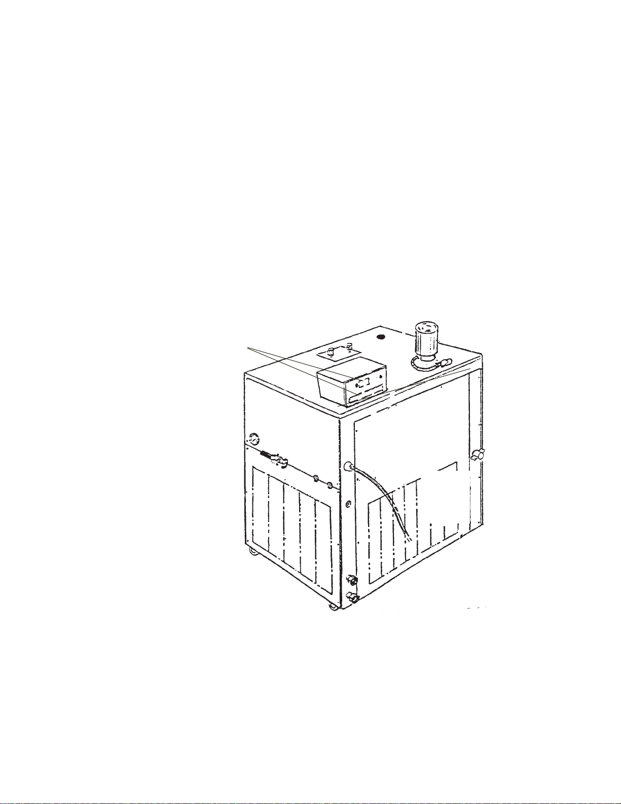
DescriptionDescription
DescriptionDescription
Description The HX Series Recirculating Chiller is designed to provide a continuous flow
of cooling fluid at a constant temperature and volume.
The unit consists of an air-cooled or water-cooled refrigeration system, a
fluid reservoir, a fluid recirculation pump, and a temperature controller.
HX units are available with a large number of options. This manual explains
how to install, operate, and maintain a “standard” HX unit. This manual also
explains some of the available options. Supplemental manuals are supplied
with units equipped with options not covered in this manual.
Throughout the manual, you will be asked to consult the unit’s serial number
label, or the pump identification label, or both, for specific information. Both
labels are located on the rear of the temperature control box.
- 6 -
+5°C to +35°C
±0.1°C
35 ¾ x 23 ¼ x 18 ¾
90.8 x 59.0 x 47.6
5.0
19.0 8.0
30.3
SpecificationsSpecifications
SpecificationsSpecifications
Specifications
HX-75HX-75
HX-75HX-75
HX-75 HX-100HX-100
HX-100HX-100
HX-100 HX-150HX-150
HX-150HX-150
HX-150
Temperature RangeTemperature Range
Temperature RangeTemperature Range
Temperature Range
Temperature StabilityTemperature Stability
Temperature StabilityTemperature Stability
Temperature Stability
Unit DimensionsUnit Dimensions
Unit DimensionsUnit Dimensions
Unit Dimensions
(H x W x D)
Inches
Centimeters
Reservoir VolumeReservoir Volume
Reservoir VolumeReservoir Volume
Reservoir Volume
Gallons
Liters
Shipping WeightShipping Weight
Shipping WeightShipping Weight
Shipping Weight
Pounds
Kilograms
HX-200HX-200
HX-200HX-200
HX-200 HX-300HX-300
HX-300HX-300
HX-300 HX-500HX-500
HX-500HX-500
HX-500 HX-750HX-750
HX-750HX-750
HX-750
Temperature RangeTemperature Range
Temperature RangeTemperature Range
Temperature Range
Temperature StabilityTemperature Stability
Temperature StabilityTemperature Stability
Temperature Stability
Unit DimensionsUnit Dimensions
Unit DimensionsUnit Dimensions
Unit Dimensions11
11
1
(H x W x D)
Inches
Centimeters
Reservoir VolumeReservoir Volume
Reservoir VolumeReservoir Volume
Reservoir Volume
Gallons
Liters
Shipping WeightShipping Weight
Shipping WeightShipping Weight
Shipping Weight
Pounds
Kilograms
320
145
+5°C to +35°C
±0.1°C
15.0
56.8
63 ¾x 46 x 29
162.0 x 116.8 x 73.6
45 7/8 x 33 ¾x 25 ¼
116.5 x 85.7 x 64.1
28.0
106.0 40.0
151.0
471
214 531
241 746
338 971
440
261
118
38 ¼x 26 ¼x 21 ¼
96.8 x 66.7 x 53.6 39 ¾x 26 ¼x 21 ¼
101.0x 66.6 x 53.6
300
136
50 5/8 x 46 x 28 ¾
128.3 x 116.8 x 73.0
1.HX-750 witha water-cooledrefrigeration systemhas thesame dimensionsas theHX-500.
- 7 -
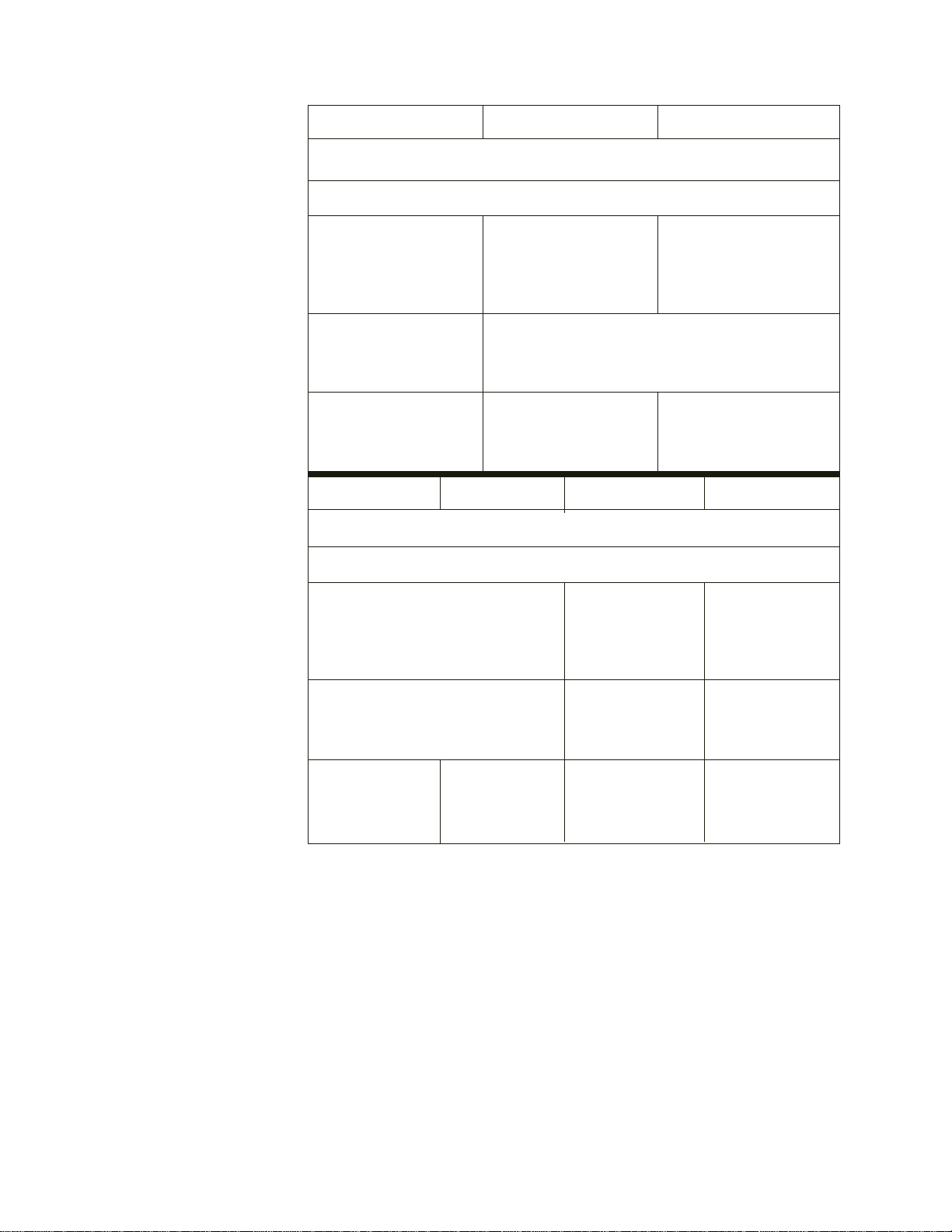
Cooling CapacityCooling Capacity
Cooling CapacityCooling Capacity
Cooling Capacity Cooling capacity will vary depending on fluid temperature, ambient
temperature, and cooling fluid.
Cooling capacities for models HX-75 through HX-750 were obtained under
the following conditions:
1. air-cooled unit operating at +20°C (+68°F) ambient temperature.
2. cooling fluid with specific heat of 1.0 was used for fluid temperatures from
+5°C to +35°C.
FluidTemperature(°C)
FluidTemperature(°C)
CoolingCapacity(Watts)
CoolingCapacity(Kilowatts)
7000
6000
5000
4000
3000
2000
1000
5 1015 20253035
A=HX-150, 60Hz
B=HX-150, 50Hz
C=HX-100, 60Hz
D=HX-100, 50Hz
E=HX-75, 60Hz
F=HX-75, 50Hz
A
B
C
D
E
F
A=HX-300, 60Hz
B=HX-300, 50Hz
C=HX-200, 60Hz
D=HX-200, 50Hz
14
12
10
8
6
4
2
5 1015 20253035
D
C
B
A
HX-75, 100, & 150HX-75, 100, & 150
HX-75, 100, & 150HX-75, 100, & 150
HX-75, 100, & 150
HX-200 & 300HX-200 & 300
HX-200 & 300HX-200 & 300
HX-200 & 300

- 8 -
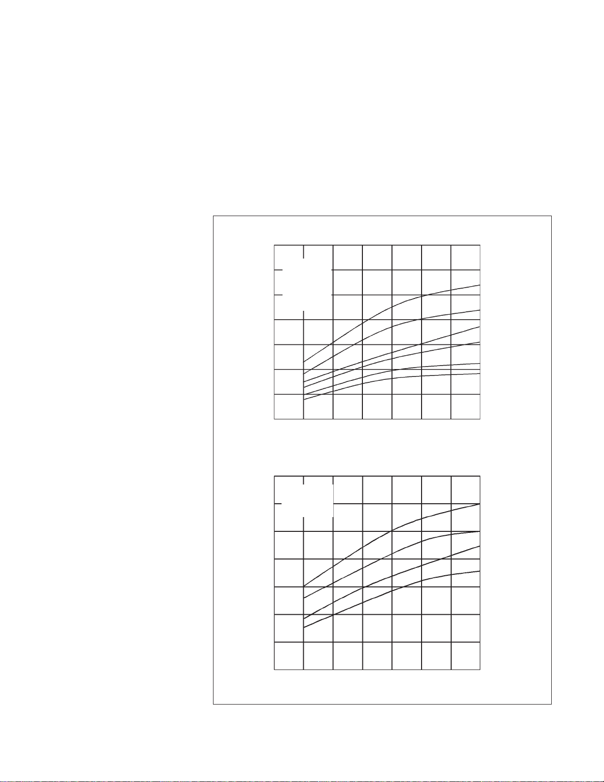
HX-500 & 750HX-500 & 750
HX-500 & 750HX-500 & 750
HX-500 & 750
FluidTemperature(°C)
A=HX-750, 60Hz
B=HX-750, 50Hz
C=HX-500, 60Hz
D=HX-500, 50Hz
35
30
25
20
15
10
5
A
B
C
D
5101520253035
CoolingCapacity(Kilowatts)
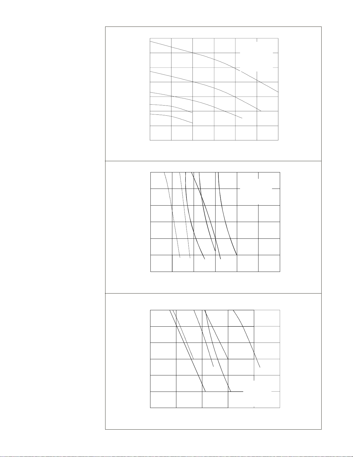
Pump CapacityPump Capacity
Pump CapacityPump Capacity
Pump Capacity HX units are available with one of three standard pump types: positive
displacement (PD), centrifugal (CP), and turbine (TU). Refer to the pump
identification label on the rear of the analog temperature controller to identify
the specific pump in your unit.
PD1, PD2 & TU1PD1, PD2 & TU1
PD1, PD2 & TU1PD1, PD2 & TU1
PD1, PD2 & TU1
A=PD-1, 50Hz
B=PD-1, 60Hz
C=PD-2, 50Hz
D=PD-2, 60Hz
E=TU-1, 50Hz
F=TU-1, 60Hz
AB
D
E
F
C
4.0 60
3.4 50
2.7 40
2.0 30
1.3 20
0.7 10
Bar PSI
12 34 56Gpm
3.8 7.5 11.3 15.1 19 22.7Lpm
FLOW
PRESSURE
- 9 -
C
PRESSURE
51015202530Gpm
18.9 37.9 56.8 60.5 94.6 113.6 Lpm
FLOW
4.7 70
4.0 60
3.4 50
2.7 40
2.0 30
1.3 20
0.7 10
Bar PSI
A
D, E
F
TU-3, 5 & 6TU-3, 5 & 6
TU-3, 5 & 6TU-3, 5 & 6
TU-3, 5 & 6
PRESSURE
AB
D
F
4.0 60
3.4 50
2.7 40
2.0 30
1.3 20
0.7 10
Bar PSI
A=TU-3, 50Hz
B=TU-3, 60Hz
C=TU-5, 50Hz
D=TU-5, 60Hz
E=TU-6, 50Hz
F=TU-6, 60Hz
4 8 12 16 20 24 Gpm
15.1 30.2 45.4 60.5 75.5 91 Lpm
FLOW
CE
PRESSURE
Bar PSI
12 16 20 24 28 Gpm
45.4 60.5 75.5 90.8 106 Lpm
4.0 60
3.4 50
2.7 40
2.0 30
1.3 20
0.7 10
A=TU-7, 50Hz
B=TU-7, 60Hz
C=TU-8, 50Hz
D=TU-8, 60Hz
E=TU-9, 50Hz
F=TU-9, 60Hz
B
A
FLOW
TU-7, 8 & 9TU-7, 8 & 9
TU-7, 8 & 9TU-7, 8 & 9
TU-7, 8 & 9
CD
EF
CPCP
CPCP
CP
A=CP-25, 50Hz
B=CP-25, 60Hz
C=CP-55, 50Hz
D=CP-55, 60Hz
E=CP-75, 50Hz
F=CP-75, 60Hz
B

- 10 -
Section III InstallationSection III Installation
Section III InstallationSection III Installation
Section III Installation
Site (Air-cooled Units)Site (Air-cooled Units)
Site (Air-cooled Units)Site (Air-cooled Units)
Site (Air-cooled Units) The unit should be located in a laboratory or clean industrial environment
where ambient temperatures are inside the range of +55°F to +95°F (+13°C
to +35°C). The unit will retain its full rated capacity in ambient temperatures
to approximately +75°F (+24°C). Above +75°F, reduce the cooling capacity
1% for every 1°F above +75°F, to a maximum ambient temperature of
+95°F. In degrees Celsius, reduce the cooling capacity 1% for every 0.5°C
above +24°C, to a maximum ambient temperature of +35°C.
Never place the unit in a location where excessive heat, moisture, orNever place the unit in a location where excessive heat, moisture, or
Never place the unit in a location where excessive heat, moisture, orNever place the unit in a location where excessive heat, moisture, or
Never place the unit in a location where excessive heat, moisture, or
corrosive materials are present.corrosive materials are present.
corrosive materials are present.corrosive materials are present.
corrosive materials are present.
The unit has an air-cooled refrigeration system. It must be positioned so the
air intake and discharge are not impeded. On models HX-75 through HX-
150, air is drawn through the left side of the unit and discharged through the
right and rear. A minimum clearance of 2 feet (0.6 meter) on these three
sides is necessary for adequate ventilation.
On models HX-200 —HX-750, air is drawn through the front of the unit and
discharged through the side and rear. A minimum of 5 feet (1.5 meters) on
all four sides of the unit is necessary for adequate ventilation.
In some applications where space is at a premium, the minimum ventilation
clearance can be compromised. However, consult our Sales Department
before positioning the unit in a location with less minimum clearance than
listed above. Inadequate ventilation will cause a reduction in cooling capacity
and, in extreme cases, compressor failure.
Excessively dusty areas should be avoided and a periodic cleaning schedule
should be instituted (see Section VII, Condenser Cleaning).
Refer to the table below to determine the approximate amount of air intake
required for the unit to retain its full rated capacity. If the air intake does not
meet these standards, cooling capacity will be derated.
HX-75 HX-100 HX-150 HX-200HX-75 HX-100 HX-150 HX-200
HX-75 HX-100 HX-150 HX-200HX-75 HX-100 HX-150 HX-200
HX-75 HX-100 HX-150 HX-200
Air IntakeAir Intake
Air IntakeAir Intake
Air Intake
Cubic feet per minute
Liters per minute
HX-300HX-300
HX-300HX-300
HX-300 HX-500HX-500
HX-500HX-500
HX-500 HX-750HX-750
HX-750HX-750
HX-750
Air IntakeAir Intake
Air IntakeAir Intake
Air Intake
Cubic feet per minute
Liters per minute
600
17000 710
20100 1050
29730 2000
56640
1900
53800 5000
141750 5600
158800

- 11 -
Site (Water-cooled units)Site (Water-cooled units)
Site (Water-cooled units)Site (Water-cooled units)
Site (Water-cooled units)The unit should be located in a laboratory or clean industrial environmentwith
easy access to a facility cooling water supply and a drain.
All units are equipped with castors for easy movement. This allows the unit
to be placed in a small area, as long as there is ample space for the unit to
be moved for access on all four sides. A minimum access clearance of 3
feet (1 meter) on two adjacent sides is recommended.
The facility cooling water supply must meet or exceed the requirements
listed in the table shown on the next page for the unit to operate at its full
rated capacity. If the facility cooling water does not meet these standards,
the cooling capacity will be derated.
As the temperature of the cooling water supply increases, the required flow
rate and pressure of the cooling water supply increases. For example, with a
model HX-150, if the temperature of the cooling water supply is +65°F, the
flow rate must be at least 1.5 gallons per minute, with a pressure differential
of at least 3.5 PSI. However, if the temperature of the cooling water supply is
+85°F, the flow rate must be at least 4.0 gallons per minute, with a pressure
differential of at least 10 PSI.
If the unit is being used with a building water supply, the back pressure of
the drain must be less than the supply pressure.
A water regulating valve, located in the TAP WATER line, regulates the flow
rate of the cooling water supply as it enters the unit. The valve regulates the
flow rate based on the heat load. Flow through the unit stops automatically
when the unit is shut off.

- 12 -
*Estimatedvalues
Temperature of cooling water supplyTemperature of cooling water supply
Temperature of cooling water supplyTemperature of cooling water supply
Temperature of cooling water supply
+55°F (+13°C)+55°F (+13°C)
+55°F (+13°C)+55°F (+13°C)
+55°F (+13°C) +65°F (+18°C)+65°F (+18°C)
+65°F (+18°C)+65°F (+18°C)
+65°F (+18°C) +75°F (+24°C)+75°F (+24°C)
+75°F (+24°C)+75°F (+24°C)
+75°F (+24°C) +85°F (+29°C)+85°F (+29°C)
+85°F (+29°C)+85°F (+29°C)
+85°F (+29°C)
HX-75HX-75
HX-75HX-75
HX-75
Flow RateFlow Rate
Flow RateFlow Rate
Flow Rate
Gallons per minute
Liters per minute
Pressure DropPressure Drop
Pressure DropPressure Drop
Pressure Drop
PSI
Bar
HX-100HX-100
HX-100HX-100
HX-100
Flow RateFlow Rate
Flow RateFlow Rate
Flow Rate
Gallons per minute
Liters per minute
Pressure DropPressure Drop
Pressure DropPressure Drop
Pressure Drop
PSI
Bar
HX-150HX-150
HX-150HX-150
HX-150
Flow RateFlow Rate
Flow RateFlow Rate
Flow Rate
Gallons per minute
Liters per minute
Pressure DropPressure Drop
Pressure DropPressure Drop
Pressure Drop
PSI
Bar
HX-200HX-200
HX-200HX-200
HX-200
Flow RateFlow Rate
Flow RateFlow Rate
Flow Rate
Gallons per minute
Liters per minute
Pressure DropPressure Drop
Pressure DropPressure Drop
Pressure Drop
PSI
Bar
HX-300HX-300
HX-300HX-300
HX-300
Flow RateFlow Rate
Flow RateFlow Rate
Flow Rate
Gallons per minute
Liters per minute
Pressure DropPressure Drop
Pressure DropPressure Drop
Pressure Drop
PSI
Bar
HX-500HX-500
HX-500HX-500
HX-500
Flow RateFlow Rate
Flow RateFlow Rate
Flow Rate
Gallons per minute
Liters per minute
Pressure DropPressure Drop
Pressure DropPressure Drop
Pressure Drop
PSI
Bar
HX-750HX-750
HX-750HX-750
HX-750
Flow RateFlow Rate
Flow RateFlow Rate
Flow Rate
Gallons per minute
Liters per minute
Pressure DropPressure Drop
Pressure DropPressure Drop
Pressure Drop
PSI
Bar
0.7* 1.0 1.5 3.0
2.8* 3.7 5.7 11.4
1.5* 2.0 3.5 8.0
0.10* 0.13 0.24 0.55
1.0* 1.5 2.0 3.5
3.7* 5.7 7.6 13.2
2.0* 3.5 5.0 10.0
0.13* 0.24 0.34 0.69
1.0* 1.5 2.5 4.0
3.7* 5.7 9.5 15.1
2.0* 3.5 6.0 10.0
0.13* 0.24 0.41 0.69
1.8* 2.5 3.5 6.0
6.8* 9.5 13.2 22.7
5.0* 6.0 7.0 18.0
0.34* 0.41 0.48 1.24
2.5* 4.0 6.5 11.0
9.5* 15.1 24.6 41.6
6.0* 8.0 13.5 25.0
0.41* 0.55 0.93 1.72
3.5 5.0 8.0 16.0
13.2 18.9 30.3 60.6
13.0 17.0 23.0 57.0
0.89 1.17 1.58 3.93
6.0 8.0 12.5 16.6
22.7 30.3 47.3 62.8
14.0 20.0 28.5 40.0
0.96 1.38 1.96 2.76
- 13 -
Electrical RequirementsElectrical Requirements
Electrical RequirementsElectrical Requirements
Electrical Requirements Refer to the table below to determine electrical requirements of your unit.
Verify the requirements by reviewing the ratings listed on the serial number
label on the rear of the case top or rear of analog temperature controller.
HX-75HX-75
HX-75HX-75
HX-75 HX-100HX-100
HX-100HX-100
HX-100 HX-150HX-150
HX-150HX-150
HX-150
208/230
60
3
200/220 380/420
50 50
3 3
208/230 380/420
60 50
3 3
N/A
VoltsVolts
VoltsVolts
Volts
HertzHertz
HertzHertz
Hertz
PhasePhase
PhasePhase
Phase
PlugPlug
PlugPlug
Plug
HX-200HX-200
HX-200HX-200
HX-200 HX-300HX-300
HX-300HX-300
HX-300 HX-500HX-500
HX-500HX-500
HX-500 HX-750HX-750
HX-750HX-750
HX-750
208/230 220/240
60
50
1 1
NEMA L6-30P or L6-20P
VoltsVolts
VoltsVolts
Volts
HertzHertz
HertzHertz
Hertz
PhasePhase
PhasePhase
Phase
PlugPlug
PlugPlug
Plug NEMA L15-30P or L16-20P
Make sure the voltage of the power source agrees with the unit’s voltage and
frequency rating. The unit is designed to tolerate deviations of ±10% from
the rated line voltage.
Models HX-75 through HX-300 have an 8 foot (2.4 meter) power cord
installed on the unit at the time of shipment.
NOTE:NOTE:
NOTE:NOTE:
NOTE: Custom units equipped with heaters may not have a power cord. See
Section VI, Special Features.
PowerCord(HX-75thruHX-300)
ElectricalConnection
(HX-500 &HX-750)

- 14 -
The unit construction provides extra protection against the risk ofThe unit construction provides extra protection against the risk of
The unit construction provides extra protection against the risk ofThe unit construction provides extra protection against the risk of
The unit construction provides extra protection against the risk of
electric shock by grounding appropriate metal parts. The extraelectric shock by grounding appropriate metal parts. The extra
electric shock by grounding appropriate metal parts. The extraelectric shock by grounding appropriate metal parts. The extra
electric shock by grounding appropriate metal parts. The extra
protection may not function unless the power cord is connected to aprotection may not function unless the power cord is connected to a
protection may not function unless the power cord is connected to aprotection may not function unless the power cord is connected to a
protection may not function unless the power cord is connected to a
properly grounded outlet. It is the user’s responsibility to assure aproperly grounded outlet. It is the user’s responsibility to assure a
properly grounded outlet. It is the user’s responsibility to assure aproperly grounded outlet. It is the user’s responsibility to assure a
properly grounded outlet. It is the user’s responsibility to assure a
proper ground connection is provided.proper ground connection is provided.
proper ground connection is provided.proper ground connection is provided.
proper ground connection is provided.
Models HX-500 and HX-750 are supplied with a disconnect box. Installation
of the cable is the user’s responsibility. Wire the unit in conformance to
local, state, and federal electrical codes. Double check all wiring to make
sure it is properly connected and protected from the elements.
Models HX-200 through HX-750 are equipped with a compressor crankcase
heater. The crankcase heater warms the oil in the compressor and prevents
refrigerant from mixing with the oil. Before start up, the unit must be
connected to its power source for at least 12 hours. This allows time for the
oil to be heated and separate from the refrigerant.
PlumbingPlumbing
PlumbingPlumbing
Plumbing
RequirementsRequirements
RequirementsRequirements
Requirements Air-cooled and water-cooled unitsAir-cooled and water-cooled units
Air-cooled and water-cooled unitsAir-cooled and water-cooled units
Air-cooled and water-cooled units
Before installing the unit to an instrument that previously used tap water as a
cooling fluid, flush the instrument several times to remove any rust or scale
that has built up. Consult the manufacturer of the instrument for a cleaning
fluid recommendation.
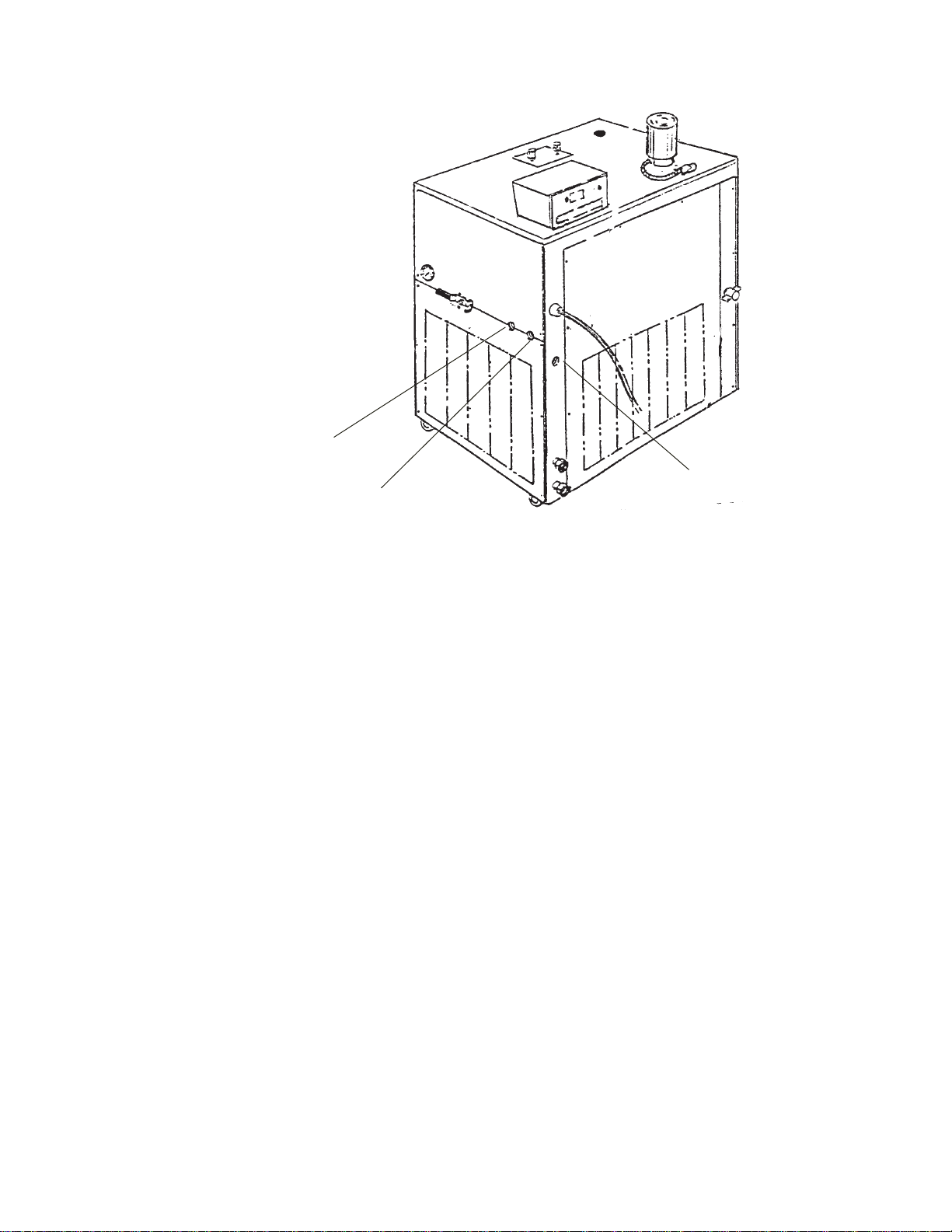
The plumbing fittings used to connect the HX to the instrument being cooled
are located on the right side of the unit (labelled SUPPLY and RETURN).
These connections are ¾inch FPT.
Remove the protective plugs from the SUPPLY and RETURN connections.
Connect the SUPPLY fitting to the inlet of the instrument being cooled.
Connect the RETURN fitting to the outlet of the instrument being cooled.
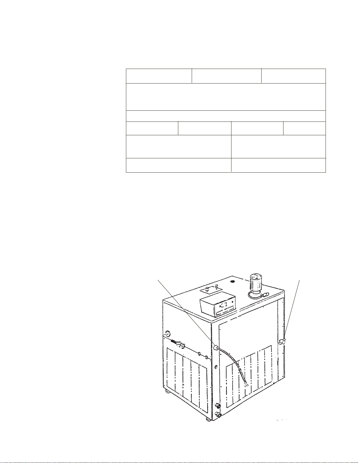
The RESERVOIR DRAIN connection on the rear of the unit is a ½inch FPT
fitting connected internally to the unit’s fluid reservoir. This fitting provides a
means for draining the reservoir. The unit is shipped with a ½inch MPT plug
installed in this fitting. Remove the plug to drain the reservoir.
- 15 -
Two plumbing adapters (¾inch MPT x 5/8 inch hose) are included with the
unit. If the unit is being plumbed to the instrument being cooled using flexible
tubing, install the adapters in the SUPPLY and RETURN plumbing ports. To
prevent leaking, wrap the threads of the adapters with Teflon®sealing tape
before installing them in the plumbing ports. The adapters will accept ½or 5/8
inch ID flexible tubing.
If the unit is "hard plumbed”to the instrument being cooled or to the cooling
water supply, damage can occur if the unit is bumped or jolted from its site.
Provisions should be made to prevent the unit from being moved after
installation. Once the unit is plumbed, secure the locking castors on the
unit’s base. If the unit is located in a heavy traffic area where the possibility
of collision is imminent, it may be necessary to secure the unit to the site
using blocks or mounting brackets.
Flexible tubing, if used, should be heavy wall or reinforced construction. All
tubing should be rated to withstand 110 psi at +35°C. Make sure all tubing
connections are securely clamped. Avoid running tubing near radiators, hot
water pipes, etc. If substantial lengths of tubing are necessary, insulation
may be required to prevent loss of cooling capacity.
Tubing and insulation are available from NESLAB. Contact our Sales
Department for more information (see Preface, After-sale Support).
It is important to keep the distance between the unit and the instrument
being cooled as short as possible, and to use the largest diameter tubing
practical. Tubing should be straight and without bends. If diameter
RESERVOIRDRAIN
SUPPLY
RETURN
- 16 -
reductions must be made, they should be made at the inlet and outlet of the
instrument being cooled, not at the HX.
If substantial lengths of connecting tubing are required, they should be
pre-filled with cooling fluid before connecting them to the unit.
Water-cooled unitsWater-cooled units
Water-cooled unitsWater-cooled units
Water-cooled units
The plumbing connections used to connect the water-cooled condenser in
the HX to the facility cooling water supply are located at the rear of the unit
(labelled TAP WATER and DRAIN). On models HX-75 through HX-300,
these fittings are ½inch FPT. On models HX-500 and HX-750, these fittings
are 1 inch FPT.
Remove the plastic protective plugs from the TAP WATER and DRAIN
connections. Connect the TAP WATER fitting to the facility cooling water
supply. Connect the DRAIN fitting to a drain.
FluidsFluids
FluidsFluids
Fluids The selected cooling fluid must have a viscosity of 50 centistokes or less at
the lowest operating temperature.
Never use flammable or corrosive fluids with this unit. Distilled andNever use flammable or corrosive fluids with this unit. Distilled and
Never use flammable or corrosive fluids with this unit. Distilled andNever use flammable or corrosive fluids with this unit. Distilled and
Never use flammable or corrosive fluids with this unit. Distilled and
deionized water may be aggressive and cause material corrosion.deionized water may be aggressive and cause material corrosion.
deionized water may be aggressive and cause material corrosion.deionized water may be aggressive and cause material corrosion.
deionized water may be aggressive and cause material corrosion.
Please contact NESLAB before subjecting this unit to prolongedPlease contact NESLAB before subjecting this unit to prolonged
Please contact NESLAB before subjecting this unit to prolongedPlease contact NESLAB before subjecting this unit to prolonged
Please contact NESLAB before subjecting this unit to prolonged
exposure to distilled or deionized water.exposure to distilled or deionized water.
exposure to distilled or deionized water.exposure to distilled or deionized water.
exposure to distilled or deionized water.
Tap water is the recommended fluid for operation from +8°C to +35°C.
Below +8°C, a non-freezing solution is required. A 50/50 mixture, by
volume, of water and laboratory grade ethylene glycol is suggested.
Do not use automobile anti-freeze. Commercial anti-freeze containsDo not use automobile anti-freeze. Commercial anti-freeze contains
Do not use automobile anti-freeze. Commercial anti-freeze containsDo not use automobile anti-freeze. Commercial anti-freeze contains
Do not use automobile anti-freeze. Commercial anti-freeze contains
silicates that can damage the pump seals. Use of automobilesilicates that can damage the pump seals. Use of automobile
silicates that can damage the pump seals. Use of automobilesilicates that can damage the pump seals. Use of automobile
silicates that can damage the pump seals. Use of automobile
anti-freeze will void the manufacturer’s warranty.anti-freeze will void the manufacturer’s warranty.
anti-freeze will void the manufacturer’s warranty.anti-freeze will void the manufacturer’s warranty.
anti-freeze will void the manufacturer’s warranty.
For units with extended temperature ranges above +35°C, tap water is the
recommended fluid up to +80°C. Above +80°C, the user is responsible for
the fluid(s) used.

- 17 -
FillingFilling
FillingFilling
Filling
RequirementsRequirements
RequirementsRequirements
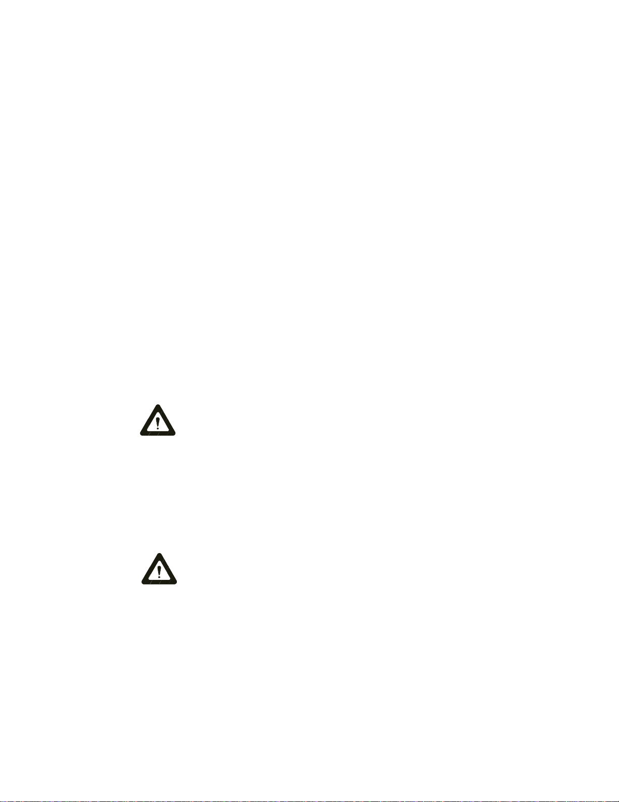
Requirements The reservoir cover is located at the left corner of the case top. Loosen the
thumbscrews and remove the reservoir cover.
Fill the fluid reservoir with cooling fluid to within 1 inch of the top.
The fluid capacity of the instrument being cooled and the recirculation lines
may be significant. To prevent the lowering of the fluid level in the reservoir
below the operating level, have extra cooling fluid on hand to keep the
reservoir filled to within 1 inch of the top.
When the recirculating system is full, replace the reservoir cover.
ReservoirCover
Thumbscrews
Pump PurgingPump Purging
Pump PurgingPump Purging
Pump Purging Models HX-100 through HX-300 with a CP-55 pump may require pump
purging. Refer to the pump identification label on the rear of the control box
to identify the specific pump in your unit.
Pump purging is necessary to purge air trapped in the pump head cavity.
Once the unit is started, open the flow control valve (see Section V, Flow
Control). It there is no flow in the SUPPLY line, or if the flow is restricted,
purging is necessary (see Section 11, Pumps to review the pump flow and
pressure specifications).
Place a container directly under the purge valve, located on the right side of
the unit, above the SUPPLY and RETURN connections. Start the unit and
open the flow control valve. Turn the PURGE valve about 1/4 clockwise.
After a few moments, cooling fluid should flow from the purge valve.
Once flow is established, close the PURGE valve and the flow control valve.
The pump is now purged and the unit is ready for operation.
Purgevalve

- 18 -
Section IV OperationSection IV Operation
Section IV OperationSection IV Operation
Section IV Operation
Start UpStart Up
Start UpStart Up
Start Up Before starting, check all electrical and plumbing connections and make sure
the recirculating system (the HX, your application, and the recirculation lines)
has been properly filled with cooling fluid.
For water-cooled units — ensure that the facility water is turned on.For water-cooled units — ensure that the facility water is turned on.
For water-cooled units — ensure that the facility water is turned on.For water-cooled units — ensure that the facility water is turned on.
For water-cooled units — ensure that the facility water is turned on.
Models HX-200 through HX-750 are equipped with a compressor crankcase
heater. The crankcase heater warms the oil in the compressor and prevents
refrigerant from mixing with the oil. Before start up, the unit must be
connected to its power source for at least 12 hours. This allows time for the
oil to be heated and separate from the refrigerant.
To start the unit, place the Power On/Off switch in the On position. The
pump and refrigeration system will start, and the POWER indicator will light.
After starting recheck the fluid level, a "top off" may be needed. To shut the
unit off, place the Power switch in the Off position.
When the unit is shut off, wait approximately 5 minutes before restarting.
This allows time for the refrigeration pressures to equalize. If the pressures
are not allowed to equalize, the compressor will short-cycle (clicking sound)
and no cooling will occur.
Refrigeration ControlRefrigeration Control
Refrigeration ControlRefrigeration Control
Refrigeration Control Turn the calibrated dial until the desired temperature aligns with the
reference line.
The refrigeration compressor runs continuously, unless the fluid temperature
exceeds +40°C. A hot gas by-pass system is used to maintain constant
temperature in all units.
The HEAT and COOL indicators, located on the control panel, indicate the
status of the refrigeration system. The HEAT indicator is lit when the unit is
in the hot gas by-pass mode. The COOL indicator is lit when the refrigeration
system is removing heat from the cooling fluid. As the fluid temperature
approaches the temperature setpoint, the indicators cycle on and off to
indicate the duty cycle of the system. The unit can be in COOL or HEAT, but
never both at the same time. A balance between COOL and HEAT controls
the temperature.
- 19 -
Flow ControlFlow Control
Flow ControlFlow Control
Flow Control The flow control handle is connected to a valve that controls the flow rate of
the cooling fluid to the instrument being cooled. The handle is located on the
right side of the unit and is labelled RECIRCULATING FLOW CONTROL.
When the handle is in the “+”position, the valve is open and all possible
cooling fluid is supplied to the instrument being cooled. When the handle is
in the “-”position, the valve is closed and no cooling fluid is supplied to the
instrument being cooled. When the handle is between these two positions,
the flow rate of the cooling fluid is between full flow and no flow. Use a flow
meter on the SUPPLY line to adjust the desired flow rate.
Never “crank”the valve wide open from the closed or slightly openNever “crank”the valve wide open from the closed or slightly open
Never “crank”the valve wide open from the closed or slightly openNever “crank”the valve wide open from the closed or slightly open
Never “crank”the valve wide open from the closed or slightly open
position.position.
position.position.
position.
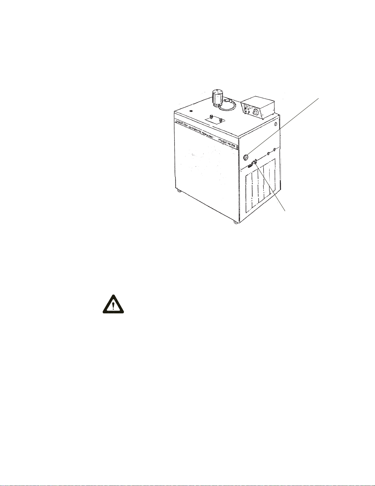
Pressure GaugePressure Gauge
Pressure GaugePressure Gauge
Pressure Gauge Units with a PD-1, PD-2, or any TU type pump are equipped with a pressure
gauge. Refer to the pump identification label on the rear of the controller to
identify the specific pump in your unit. The RECIRCULATING PRESSURE
gauge is located next to the flow control handle. The gauge indicates the
operating pressure of the system.
FlowControlValve
RECIRCULATINGPRESSUREgauge
This manual suits for next models
7
Table of contents
Popular Chiller manuals by other brands

Carrier
Carrier Flotronic 30GB user manual

CIAT
CIAT LJ 65/75 manual

Galletti
Galletti LCX Series user manual

Fast Chiller
Fast Chiller TT3 user guide

York
York YCAL0043E Series Installation operation & maintenance

Carrier
Carrier AquaSnap 30RAP011-060 Controls, start-up, operation, service, and troubleshooting

ascon
ascon 4AC20C installation manual

AERMEC
AERMEC FCX Direction for use and installation

Thermo Scientific
Thermo Scientific thermoflex Installation, operation and maintanance

SMC Networks
SMC Networks HRSH100-A*-20 Series Operation manual

Scilogex
Scilogex SCIP5-20 operating instructions

1TAC
1TAC 1Hydro user manual


