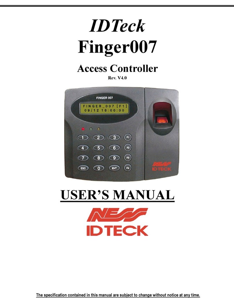
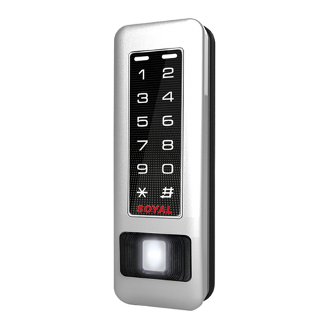
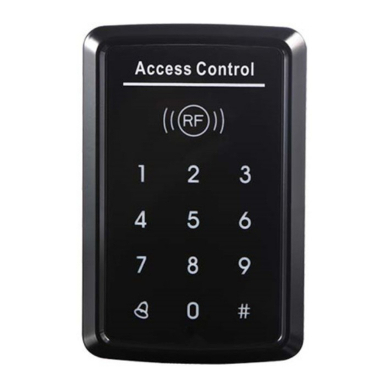
NESS ID TECK PIN120 User manual

IDTeck
PIN120
Single Door Controller
V2.0
USER’S MANUAL

101-040 2 PIN120
IDTeck – PIN120 Keypad System
CONTENTS
1. Important Safety Instructions
2. Introduction
3. Identifying Supplied Parts
4. Specification
5. Installation
6. Wire Color Table
7.WireConnection
8. Operation
9. FCC Registration Information
10. Contacts

101-040 3 PIN120
IDTeck – PIN120 Keypad System
1. Important safety instructions
To prevent injuries to persons and damages to property, please read all the instructions and follow
them whenever you deal with this product.
After reading, please put this instruction manual where it can be easily seen for the system operator.
ON INSTALLATION AND POWER
Use 12V DC power ONLY
- Connecting to higher than 12V DC may result in a risk of electric shock, fire, or heavy damage of the unit.
Do NOT install this product at places with wet or metallic dust, or that can be watered.
- There may be risks of electric shock and fire.
Do NOT install this product near electric motors running.
- The unit may not operate normally.
Do NOT set this product near heaters or any thing that produces heat.
- There may be a risk of fire.
Be ALWAYS careful not to short-circuit any part of the circuitry with tools like a screwdriver in hand.
- There may be a risk of fire or heavy damage of the unit.
ON MAINTENANCE
Do NOT use any kind of liquid for cleaning.
- There may be a risk of electric shock, fire or heavy damage of the unit. Use an air spray, if needed.
Users are cautioned NOT to attempt repair of this product or modify the wirings set by the installer at there
own discretion.
- It may pose the risk of fire, hardware damages, or abnormal operations of the unit.
It is recommended not to use a flammable spray or something easy to burn near this product.
- There may be the risk of an explosion or fire.
Keep the unit away from any unauthorized people.
- It may cause abnormal operations of the unit.
NOTICE
Please, contact a designated service centre or the outlet at which the product was purchased when
A. Any liquid has been spilt or sprayed onto the product. In this case, cut the power off first.
B. The product seems to be operating abnormally.
C. The unit exhibits a distinct change in performance.
D. The unit has fallen to be broken down or damaged on its case.
* The cost of repairing can be charged for troubles due to the improper handling or negligence of users
or the operator.

101-040 4 PIN120
IDTeck – PIN120 Keypad System
2.Introduction
The NESS - IDTECK PIN120 is an intelligent single door keypad / controller that combines the
convenience of entry control with the security of an alarm system. Also, the NESS - IDTECK PIN120
system will give you field proven reliability and cost-effective solution anywhere access controls and
security are required. The NESS - IDTECK PIN120 can interface and operate with EXIT button. Also,
output ports, which include 2 Relays and 1 Bell. Moreover, the status or behaviours of these input and
output accessories are configurable to provide the system administrator with complete customized control
of the system.
3.Identifyingsuppliedparts
Please unpack and check the contents of the box.
MAINUNIT WALLMOUNT O-RING USERSMANUAL
(1ea) (1ea) (5ea) (1ea)

101-040 5 PIN120
IDTeck – PIN120 Keypad System
4.Specification
5.Installation
zDrill two 6-32 or M3 holes 3.3"(8.38cm) apart in
vertical and one 1/2" hole at the centre of these two
holes. (If you have installed electric gang box then
skip this step.)
zUsing two 6-32 or M3 screws, install wall mount to
the wall.
zInsert 5 O-rings to the wall mount as indicated, then
route the cable of the main unit through the centre
hole and push the main unit to wall mount to lock
the main unit and make sure that the main unit is
locked with wall mount.
Input Voltage/Current DC 12V, Max. 160mA
PIN numbers 512 PIN number(4 ~ 6 digits), 1 Master ID(6 digit),
Input/Output ports Input : Exit, Output : 2 form-c relay, Chime bell output
Keypads 12 numeric keypad
LED/Buzzer 3 LEDs (Red, Green, Yellow) / Piezo Buzzer
Operating Environment -35 ~ +65 (-31 ~ 149), 10 ~ 90% RH (Non-Condensing)
Colour Dark pearl grey
Overall Size(WxHxD) 3.4" x 3.94" x 1.22" (87 x 100 x 31mm)
Weight 162g(0.36lbs)

101-040 6 PIN120
IDTeck – PIN120 Keypad System
6.WireColourTable
POWER
Power (DC +12V) DC (+) Red wire
Power (DC Ground) DC (-)(GND) Black wire
INPUT
EXIT input EXIT White
OUTPUT
Door Relay (COM) D_COM Green
Door Relay (NO) D_NO Purple
Door Relay (NC) D_NC Blue
Alarm Relay (COM) A_COM Yellow
Alarm Relay (NO) A_NO Grey
Alarm Relay (NC) A_NC Orange
Chime Bell BELL Brown

101-040 7 PIN120
IDTeck – PIN120 Keypad System
7.WireConnection

101-040 8 PIN120
IDTeck – PIN120 Keypad System
8.Operation
8-1. Initial Settings
zPIN120 is completely blank when it is delivered to customer. The unit automatically enters to initial
setting mode (program mode) when it is powered up.
zYou may also erase all memory by turn on the power after connecting 2wires. (White and Brown)
zProgramming sequence is as follows:
Connect 12V DC Power supply to RED (+) and BLACK (-) wire then power up
You can hear the tune “Sol-Fa-Mi-Re-Do~” and all three LEDs on
Press the keypads as follow.
(6 digit Master ID) + (ENT) Tune (Do-Do-Mi-Mi-Sol-Sol) red & green LED on
(4~6 digit Access ID) + (ENT) Tune (Mi-Do) red LED on
…
[PIN Access Code[ (Up to 512 Access ID) + (ENT) Tune (Mi-Do)
(6 digit Master ID) + (ENT) Tune (Do-Sol-Mi--Do~)
Example) You want to set Master ID “123456” and Access ID “1111”, ”22222” and “345678”.
“123456” + (ENT) : Register Master ID
“1111” + (ENT) : Register Access ID
“22222” + (ENT) : Register Access ID
“345678“+ (ENT) : Register Access ID
“123456” + (ENT) : Finish Setting
Note: Master ID must be 6 digits long and Access ID is 4~6 digit and (ESC) key is to cancel the key
input, for example if you want to press “123456” but you pressed “112345” then press ESC key
to cancel “112345” then press “123456” + (ENT) to correction.
The unit now enters to normal operation mode.
With above sequence you already registered “MASTER ID” and “USER ACCESS ID” and the
other default settings are automatically set and stored into flash memory.

101-040 9 PIN120
IDTeck – PIN120 Keypad System
8-2. Default Setting Values
8-3. Normal Operation
zYellow LED is blinking every second.
zOperating Outputs: 4 ~ 6 digits Access ID + ENT
zIf Access ID is granted, Door Relay and green LED activates.
zIf Access ID is denied, Alarm Relay and red LED activates.
zExit Input Entered: Door Relay and green LED activates.
zQuick Access (only activates when Quick Access Mode ON): ENT
Door Relay and green LED activates
zBELL (only activates when BELL Output Time set): ESC
Bell output (open collector) activates with bell sound.
When Access ID Granted Door Relay and green LED activate for 3 seconds
Exit Input Entered Door Relay and green LED activates for 3 seconds
When Access ID denied Alarm Relay and red LED activates for 2 seconds (within Try-out count)
When Try-out error occur Alarm Relay and red LED activates for 2 seconds and Keypad locks for
60 seconds (from 3rd Try-out).
Bell (ESC) key pressed Bell sound (Mi-Do~ Mi- Do~),
Bell output (open collector) activates for 5 seconds
Numbers of Try-out count 3 times
Keypad input limit time 20 seconds
Keypad lock time 60 seconds
Bell output Enable
Silent mode Off
Tamper Alarm Off
Quick Access code Disable

101-040 10 PIN120
IDTeck – PIN120 Keypad System
8-4. Setting Changes
Reset All Outputs (all Relays and Bell output OFF) Master ID+ENT
Add New Access ID Master ID+ENT+11+ENT+New Access ID+ENT
Delete Access ID Master ID+ENT+13+ENT+Delete Access ID+ENT
Door Relay Time Set:
Time = 00 ~ 99 seconds Master ID+ENT+21+ENT+TIME+ENT
Alarm Relay Time Set:
Time = 00 ~ 99 seconds Master ID+ENT+22+ENT+TIME+ENT
Bell Output Time Set:
Time = 00 ~ 99 seconds Master ID+ENT+23+ENT+TIME+ENT
Keypad Input Limit Time Set:
Time = 10 ~ 99 seconds Master ID+ENT+25+ENT+TIME+ENT
Key Lock Time Set:
Time 00 ~ 99 seconds Master ID+ENT+26+ENT+Key Lock Time+ENT
Try-Out Count Set:
Count = 00 ~ 99 times Master ID+ENT+27+ENT+COUNT+ENT
Door Relay Latch (unconditional ON) Master ID+ENT+31+ENT
Alarm Relay Latch (unconditional ON) Master ID+ENT+32+ENT
Bell Output Latch (unconditional ON) Master ID+ENT+33+ENT
Tamper Alarm ON Master ID+ENT+41+ENT
Tamper Alarm OFF Master ID+ENT+42+ENT
Silent Mode OFF Master ID+ENT+51+ENT
Silent Mode ON Master ID+ENT+52+ENT
Quick Access Mode ON Master ID+ENT+61+ENT
Quick Access Mode OFF Master ID+ENT+62+ENT
Master ID Change Master ID+ENT+90+ENT+New Master ID+ENT
Erase All Memory And Initialise Settings Master ID+ENT+99+ENT+Master ID+ENT

101-040 11 PIN120
IDTeck – PIN120 Keypad System
10.Contacts
Ness Security Products Pty Ltd
ABN 28 069 984 372
Head Office – NSW:
4 / 167 Prospect Hwy
Seven Hills, NSW, 2147 – Australia
Ph +61 2 8825 9222
Fax + 61 2 9674 2520
www.ness.com.au
email:[email protected]
NSW:
4 / 167 Prospect Hwy
Seven Hills, NSW, 2147
Ph (02) 8825 9222
Fax (02) 9674 2520
Vic:
24 Terracotta Drive
Blackburn, Vic, 3130
Ph (03) 9875 6400
Fax (03) 9875 6422
QLD:
Unit 3A / 471 Lytton Road
Morningside, Qld, 4170
Ph (07) 3399 4910
Fax (07) 3217 9711
W.A:
Unit 1, 567 Newcastle Street
Perth, W.A., 6000
Ph (08) 9328 2511
Fax (08) 9227 7073

101-040 12 PIN120
IDTeck – PIN120 Keypad System
Table of contents
Other NESS ID TECK IP Access Controllers manuals
Popular IP Access Controllers manuals by other brands

Identiv
Identiv uTrust TouchSecure Wall Mount user manual
Roger
Roger MCT88M-IO operating manual
TCS
TCS codelock12 Product information
ACT Technology
ACT Technology ACT1000 - ACCESS CONTROL UNIT - INSTALLERS Operator instructions
KeyGuard
KeyGuard Transparent Door Installation and operation manual
Paxton
Paxton TOUCHLOCK K Series instruction manual
