Ness L300 User manual
NESS L300 User Guide i
NESS L300
User Guide

ii
User Guide
Copyright
© 2005 NESS Ltd.
All rights reserved.
No part of this publication may be reproduced, transmitted, transcribed, stored in a retrieval
system, or translated into any language or any computer language, in any form or by any third
party, without the prior written permission of NESS Ltd.
Trademarks
NESS is a trademark of NESS Ltd.
NESS L300 is a trademark of NESS Ltd.
Disclaimer
NESS Ltd. Shall not be liable for any injury or damage suffered by any person, either directly or
indirectly, as a result of the unauthorized use or repair of NESS Ltd's products. NESS Ltd.
does not accept any responsibility for any damages caused to its products, either directly or
indirectly, as a result of use and/or repair by unauthorized personnel.
Environmental Policy
Service personnel are advised that when changing any part of the NESS L300,
care should be taken to dispose of those parts in the correct manner; where
applicable, parts should be recycled.
When the lifecycle of the NESS L300 TM has been completed, the product should
be discarded according to the laws and regulations of the local authority.
For more detailed information regarding these recommended procedures, please
contact your local or regional NESS L300 distributor.
NESS is committed to continuously seeking and implementing the best possible
manufacturing procedures and servicing routines.
Caution: Federal law restricts this device to sale by or on the order of a
practitioner licensed by the law of the State in which he/she
practices to use or order the use of the device.

NESS L300 User Guide iii
Manufacturer
NESS Ltd. 19 Ha'haroshet St., Keidar Center
P.O. Box 2500, Ra'anana 43654, Israel
Tel: (972) 9-748-5738 Fax: (972) 9-748-5740
Email: ness@ness.co.il
Website: www.NESSLTD.com
U.S. Distributor
Bioness Inc. 25134 Rye Canyon Loop Suite 300
Santa Clarita, California 91355
Tel: (800) 211-9136 Fax: (661) 702-6707
Email: info@bionessinc.com
Website: www.bionessinc.com
European Distributor
NESS Europe, Zadelmakerstraat 53
2984 CC Ridderkerk, The Netherlands
Tel: 31-180-481600 Fax: 31-180-463752
Email: ness@ness.nl
Website: www.ness.nl

iv
Table of Contents
1. INTRODUCTION TO YOUR NESS L300............................................. 1
C
LINICAL
A
SPECTS
..................................................................................1
A
DVANCED
T
ECHNOLOGY IN
R
EHABILITATION
............................................1
F
OR
Y
OUR
H
EALTH AND
S
AFETY
...............................................................3
Contraindications ...................................................................................3
Warnings................................................................................................3
Precautions............................................................................................4
A
DVERSE
R
EACTIONS
..............................................................................6
R
ADIO
C
OMMUNICATION
I
NFORMATION
......................................................6
2. GENERAL OVERVIEW OF YOUR NESS L300.................................. 7
C
OMPONENTS OF THE
NESS
L300...........................................................7
T
HE
O
RTHOSIS
........................................................................................8
Indicator lights on the orthosis electronic module...................................9
T
HE
F
OOT
S
ENSOR
..................................................................................9
T
HE
C
ONTROL
U
NIT
...............................................................................11
Control Unit Buttons and Display..........................................................12
Operating the Control Unit....................................................................13
Control Unit Display and Audio Indications...........................................16
3. OPERATING MODES........................................................................... 18
S
TANDBY MODE
.....................................................................................18
G
AIT MODE
............................................................................................18
T
RAINING MODE
.....................................................................................18
4. DAILY USE OF YOUR NESS L300..................................................... 19
A
CTIVATING AND
U
SING THE
S
YSTEM
......................................................19
P
UTTING ON THE ORTHOSIS
....................................................................19
Positioning the orthosis on the leg........................................................20
T
AKING OFF THE
O
RTHOSIS
....................................................................24
5. CARE AND MAINTENANCE.............................................................. 25
C
HARGING THE
B
ATTERIES
.....................................................................27

NESS L300 User Guide v
R
EPLACING THE
B
ATTERIES
....................................................................29
Orthosis Electronic Module...................................................................29
Foot Sensor..........................................................................................29
Control Unit..........................................................................................30
R
EPLACING
E
LECTRODES
.......................................................................31
C
LEANING YOUR
NESS
L300 .................................................................32
6. REPLACING AND INSTALLING SYSTEM COMPONENTS........33
R
EPLACING AND REGISTERING COMPONENTS
...........................................33
R
EMOVING AND
I
NSTALLING THE
O
RTHOSIS
E
LECTRONIC
M
ODULE
...........35
Placing a Foot Sensor in your Shoe.....................................................36
7. ACCESSORIES....................................................................................... 38
8. TROUBLESHOOTING.......................................................................... 39
9. SPECIFICATIONS................................................................................. 44
L
IST OF
S
YMBOLS
..................................................................................50

vi
Table of Figures
Figure 1: L300 System Components................................................................. 7
Figure 2: The Orthosis ........................................................................................ 8
Figure 3: Foot Sensor ....................................................................................... 10
Figure 4: Control Unit........................................................................................ 12
Figure 5: Positioning the Leg............................................................................ 20
Figure 6: Placing the Orthosis on the Leg ........................................................ 21
Figure 7: Fastening the Strap ...........................................................................22
Figure 8: Orthosis Fastened in Place ............................................................... 23
Figure 9: Control Unit Charger Socket.............................................................. 28
Figure 10: Charging the Batteries..................................................................... 28
Figure 11: Charging Indicators ......................................................................... 28
Figure 12:Foot Sensor and Battery................................................................... 30
Figure 13: Control Unit and Battery.................................................................. 30
Figure 14: Digital Display while Registering..................................................... 34
Figure 15: Removing the electronic module from the orthosis......................... 35
Figure 16: Foot Sensor in Place (Left Shoe Shown)........................................ 36
Figure 17: Transmitter in Place on a Right Shoe.............................................. 37

NESS L300 User Guide 1
1. Introduction to your NESS
L300
Clinical Aspects
The NESS L300 system is intended for improving gait in people suffering
from drop foot as a result of a central nervous system injury or disease.
Drop foot is the inability or partial ability to raise the foot and toes toward
the body (dorsiflexion). This condition is a common result of impairment
or injuries to the central nervous system such as stroke, traumatic brain
injury, multiple sclerosis, or cerebral palsy. Patients with drop foot tend
to drag their foot during the swing phase of walking and usually try to
compensate for the dragging by hiking their hip or swinging it in a
circular motion (circumduction). These patients tend to be less stable,
suffer the risk of frequent falls, and expend more energy when walking.
The NESS L300 is intended to provide ankle dorsiflexion in individuals
with drop foot. During the swing phase of gait, the NESS L300
electrically stimulates muscles in the weak leg to provide flexion of the
foot; thus, it may improve the individual’s gait. The NESS L300 also may
facilitate muscle re-education, reduce muscle spasm, prevent/retard
disused atrophy, maintain or increase joint range of motion and increase
local blood flow.
Advanced Technology in Rehabilitation
The NESS L300 system is comprised of an electronic orthosis, a foot
sensor, and a control unit, which are ergonomically designed and
aesthetically pleasing. The advanced ergonomic design of the orthosis
ensures constant and snug contact of each electrode during limb motion
and muscle contraction.

2
The NESS L300 system stimulates the common peroneal nerve in the
lower leg causing the muscles that lift the foot and toes to contract.
During walking the foot sensor detects when the foot is off the ground
and sends a radio signal which initiates the stimulation causing the foot
to move in a natural motion according to your walking pattern.

NESS L300 User Guide 3
For Your Health and Safety
Contraindications
•Patients with a demand-type cardiac pacemaker should not use
the NESS L300.
•Stimulation should not be applied over, or in proximity to,
cancerous lesions.
•The NESS L300 should not be used over areas of regional
disorders, such as a fracture or dislocation, which would be
adversely affected by motion from the stimulation.
Warnings
•The long-term effects of chronic electrical stimulation are
unknown.
•The orthosis should not be applied over swollen, infected, or
inflamed areas or skin eruptions, e.g., phlebitis, thrombophlebitis,
varicose veins, etc.
•Simultaneous connection of the L300 to the patient and to high-
frequency surgical equipment may result in burns at the site of
the stimulator electrodes and possible damage to the electronic
module of the orthosis.
•Do not use the NESS L300 in close proximity (less than 3 feet) to
short wave or microwave therapy equipment as it may produce
instability in the orthosis electronic module output.
•System configuration should only be performed by an authorized
clinician.

4
Precautions
•Patients with an implanted electronic device (for example a cardiac
pacemaker) should not be subjected to stimulation unless specialist
medical opinion has first been obtained.
•Inflammation in the region of the NESS L300 may be aggravated by
motion, muscle activity or pressure from the orthosis. Use of the device
should be temporarily halted until the inflammation clears.
•Caution should be used for patients with suspected or diagnosed heart
problems.
•Caution should be used in the presence of the following:
oWhen there is a tendency to hemorrhage following acute trauma
or fracture.
oFollowing recent surgical procedures when muscle contraction
may disrupt the healing process.
oOver areas of the skin which lack normal sensation.
•Caution should be used for patients with suspected or diagnosed
epilepsy.
•Some patients may experience skin irritation or hypersensitivity due to
the electrical stimulation or electrical conductive medium. The irritation
can usually be reduced by using an alternate conductive medium or
alternate electrode placement.
•Electrode placement and stimulation settings should be based on the
guidance of the prescribing practitioner.
•The NESS L300 should be used only with electrodes supplied by NESS
Ltd.
•Specific physician clearance should be obtained prior to use in patients
with alteration of normal arterial or venous flow due to local
insufficiency, occlusion, arterio-venous fistula for the purpose of
hemodialysis, or primary disorder of the vasculature.

NESS L300 User Guide 5
•Specific physician clearance should be obtained when there is a
structural deformity or placement of metal implant in the area to be
stimulated.
•The safety of the NESS L300’s use during pregnancy has not been
established.
•Skin problems in areas of contact with the orthosis may be aggravated
by use of the NESS L300.
•The NESS L300 should be turned off before removing or replacing the
electrodes.
•The NESS L300 should be kept out of the reach of children.
•The NESS L300 Control Unit is splash proof. However, it should be
protected it from any contact with water such as dampness from sinks,
bathtubs and shower stalls, from weather such as rain or snow or any
other source of water.
•Do not leave the NESS L300 stored in a car in hot weather where the
temperature may exceed the recommended storage temperature and
could cause damage to the device.
•Should any technical problem occur, that is not covered in the
troubleshooting section of this manual; contact your clinician or NESS
L300 distributor. Do not attempt to repair your NESS L300.
•The orthosis is meant to be worn only on the leg of the user for whom it
is fitted. It should not be applied to anyone else or any other part of the
body.
•Put on the orthosis only when the NESS L300 is turned off. Do not
activate it until it is fastened in place.
•The system should not be used while driving, operating machinery, or
during any activity in which involuntary muscle contractions may put the
user at undue risk of injury.

6
Adverse Reactions
In the unlikely event of any of the following occurrences, stop using your NESS
L300 immediately and consult your personal physician.
•Signs of significant skin irritation or pressure sores on the limb in areas
of contact with the orthosis.
•A significant increase in muscle spasticity.
•A feeling of heart-related stress during stimulation.
•Swelling of the leg, knee, ankle, or foot.
•Any other unanticipated reaction.
Radio Communication Information
This device complies with Part 15 of the FCC Rules. Operation is subject to the following
two conditions
(1) This device may not cause harmful interference.
(2) This device must accept any interference received, including interference that
may cause undesired operation.
Parts of the NESS L300 communicate via radio communication and have been tested and found
to comply with the limits for a Class B digital device, pursuant to Part 15 of the FCC Rules.
These limits are designed to provide reasonable protection against harmful interference in a
residential installation. This equipment generates, uses and can radiate radio frequency energy
and, if not installed and used in accordance with the instructions, may cause harmful
interference to radio communications. However, there is no guarantee that interference will not
occur in a particular installation. If this equipment does cause harmful interference to radio or
television reception, which can be determined by turning the equipment off and on, the user is
encouraged to try to correct the interference by one or more of the following measures:
•Reorient or relocate the receiving antenna.
•Increase the separation between the equipment and receiver.
Consult the dealer or an experienced radio/TV technician for help.
Changes or modifications to this equipment not expressly approved by the NESS Ltd.
could void the user’s authority to operate the equipment.
The antenna for each transmitter must not be co-located or operating in
conjunction with any other antenna or transmitter.

NESS L300 User Guide 7
2. General Overview of your
NESS L300
Components of the NESS L300
The NESS L300 is supplied with the following components:
oControl Unit
oOrthosis
oOrthosis Electronic Module
oFoot sensor
oElectrodes
oCarrying case
oUser Manual
oCharger (supplied separately)
Figure 1: L300 System Components in carrying case

8
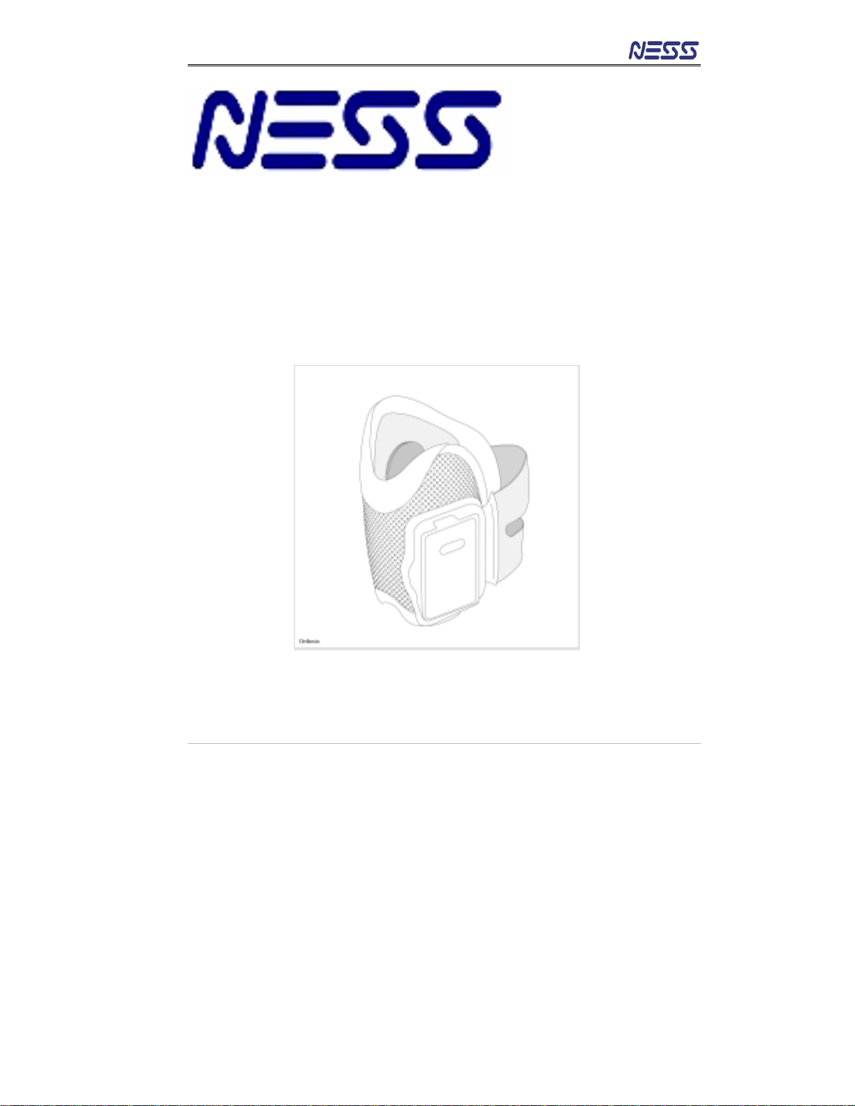
The Orthosis
Figure 2: The Orthosis
•The orthosis is light weight and has a low profile allowing it to
be easily positioned under trousers.
•It is anatomically designed to allow accurate placement on
the leg.
•An electronic module containing the stimulator, battery and
communication circuit, is integrated into the orthosis cradle. It
may be snapped in or out of the orthosis for maintenance or
cleaning.
•The entire device is held in place by an adjustable elastic
strap which may be fastened easily using one hand.
•Two electrodes are attached to their bases on the inner lining
of the orthosis. Their position in the orthosis has been
Electronic Module
Handle
Locator
Electrode base
& electrode
Cradle
Elastic Strap
Status light Stimulation light

NESS L300 User Guide 9
carefully determined by the clinician during fitting. The
electrodes may be easily replaced by the user without
changing their positions
Indicator lights on the orthosis electronic
module
Indicator lights on the electronic module display the status of the unit
and when stimulation occurs.
System on Flashes green
Low battery Flashes yellow
Charging Alternating between
yellow and green
Battery fully charged Constant Green
Status Light
Malfunction Constant or flashing
red light
Stimulation applied Flashes rapid yellow
Stimulation Light Stimulation inactive Flashes slow yellow
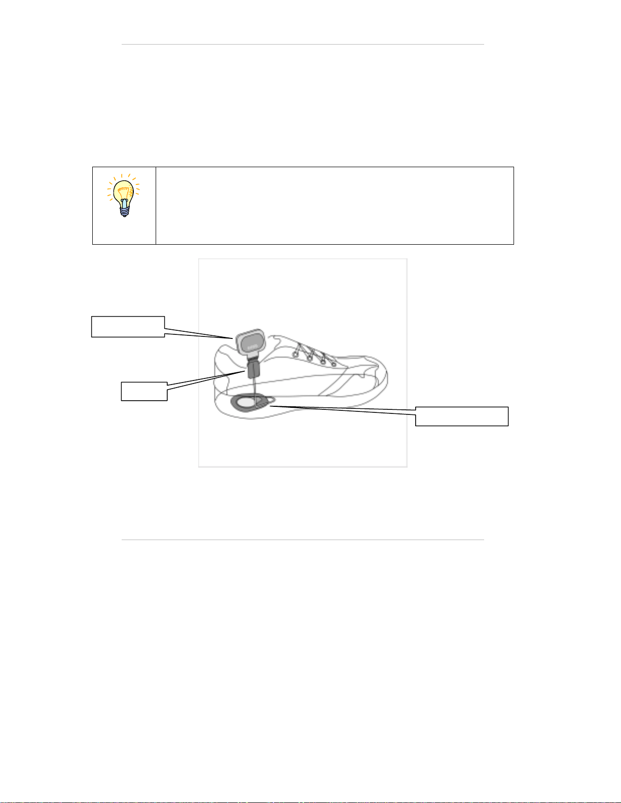
The Foot Sensor
The foot sensor (Figure 3) detects whether the foot is on the ground or in
the air and transmits radio signals to the electronic module in the
orthosis, according to which the stimulation is activated.
The foot sensor consists of a pressure sensor worn underneath the inner
sole of the shoe, along with a small transmitter attached to the upper
edge of the shoe by a special clip.
10
There is no need to detach the foot sensor between uses.
The foot sensor transmitter is powered by a small non-rechargeable
battery which needs replacing approximately every six months of use.
The foot sensor by default should be placed under the paretic (weak)
foot. In some cases the foot sensor may be placed under the non-paretic
foot according to a clinician's judgment.
Note
The foot sensor should be placed only under the foot designated by
the clinician.
Figure 3: Foot Sensor
Transmitter
Pressure Sensor
Clip

NESS L300 User Guide 11
The Control Unit
The control unit (see figure 4) enables the user to activate/deactivate the
system, select the operation mode, fine-tune the stimulation intensity
and receive information regarding the system by visual and audio
indicators.
It can be carried around the neck using the neck strap supplied, in a
pocket or belt pouch.
It is powered by a single rechargeable AAA battery.
During operation, the control unit maintains two-way communication with
the electronic module in the orthosis. If communication is lost the
system will cease working.
Operating Button Description
ON/OFF Turns the control unit ON and OFF
Trigger mode Selects Gait, Training or Standby Mode
Volume Adjustment Adjusts the volume of the audio
indications
Intensity Adjustment Adjusts the intensity of stimulation

12
Control Unit Buttons and Display
Figure 4: Control unit buttons and display
ON/OFF Button
Trigger Mode
Button
Intensity Level
Buttons
Neck Strap Hole
Control Unit
indicator light
Intensity
Indicator
Foot Sensor
Indicator Light Orthosis
Indicator Light
Volume Adjustment
buttons

NESS L300 User Guide 13
Operating the Control Unit
Turning on the system
Press the On/Off button once. The system will automatically start in
Standby Mode. All display indicators will light up for a few seconds
while the system performs a self-test, then the On/Off button flashes
green to indicate that the system is activated.
Selecting the Mode
To select the Gait Mode: after the unit is turned on, press the trigger
mode button once briefly. You should hear a beep and the trigger mode
button will begin to blink slowly. During stimulation the button blinks
rapidly.
To select the Training Mode: after the unit is turned on, press the
trigger button and hold it for 3 seconds (long press), until a beep is
heard. The trigger mode button will begin to blink slowly. In addition, the
intensity indicator displays a “t” alternating with the intensity.
To go back to the Standby Mode: from the Gait or Training mode,
press the trigger button again briefly, you should hear a beep, and the
trigger mode button will stop blinking.

14
Adjusting the stimulation intensity level
During the fitting process your clinician set the stimulation type and
intensity according to your exact needs, normally there is no need to
adjust the stimulation intensity however it may be necessary while
walking on different surfaces or with various footwear.
To lift the foot higher:
If the foot slightly drags or catches on the floor while walking the
stimulation level should be increased by pressing the "+" button.
To decrease foot lift:
If you feel that your foot rises too high while walking or that the
stimulation is unpleasant, the intensity level can be reduced by pressing
the "-" button. After reducing the intensity take care that your foot doesn’t
drag or catch on the floor.
•When the intensity level is altered the intensity level appears
on the display of the control unit and a corresponding beep is
emitted
•When the system is turned on the intensity is automatically
set to “5” which is the intensity set by the clinician if the
intensity is reduced to “0” there will be no stimulation.
Note
Do not increase the stimulation intensity level set for you by your
clinician by more than two levels without first consulting him or her.
Table of contents
Popular Medical Equipment manuals by other brands


Thuli Tables
Thuli Tables Tour owner's manual

Invacare
Invacare Head and Torso Supports 1164 Installation and operating instructions

Handicare
Handicare System RoMedic PositioningCover user manual

ResMed
ResMed Astral Series user guide

Kegel8
Kegel8 Tight & Ton user guide

Storz
Storz TAKE-APART Instructions for use


