2. INSTALLATION
2.1. Unpacking
2.1.1. Chair
2.1.1.1. Cut the shipping bands, open the top of the
shipping carton, and remove all packing material and boxes
that can be easily reached. Remove (4) nuts and remove
both base clamping boards.
2.1.1.2. It is recommended that the skid be positioned as
close as possible to the desired chair location.
2.1.1.3. Remove at least two small shipping blocks stapled
to the top of the skid. The chair can now be slid and/or
tipped from the skid onto the floor.
2.1.1.4. Do not lift the chair by the upper structure.
However, the chair may be tipped or slid into position by
pushing or pulling on the upper structure.
2.1.1.5. With the chair in positon, remove all remaining
paper pads, plastic, tape, strings, etc.
2.2. Assembly
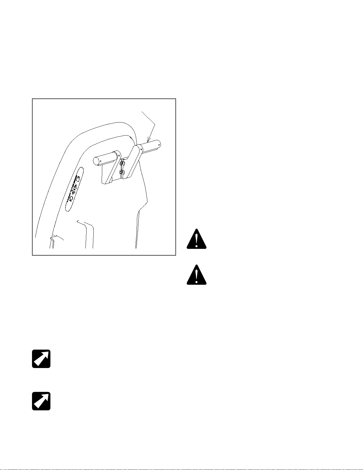
2.2.1. Headrest
2.2.1.1. Remove the headrest from its carton, and mount
it into position onto the chair back. Using the proper hex
key wrench, tighten the cap screw to clamp the headrest
securely into its mounting bracket.
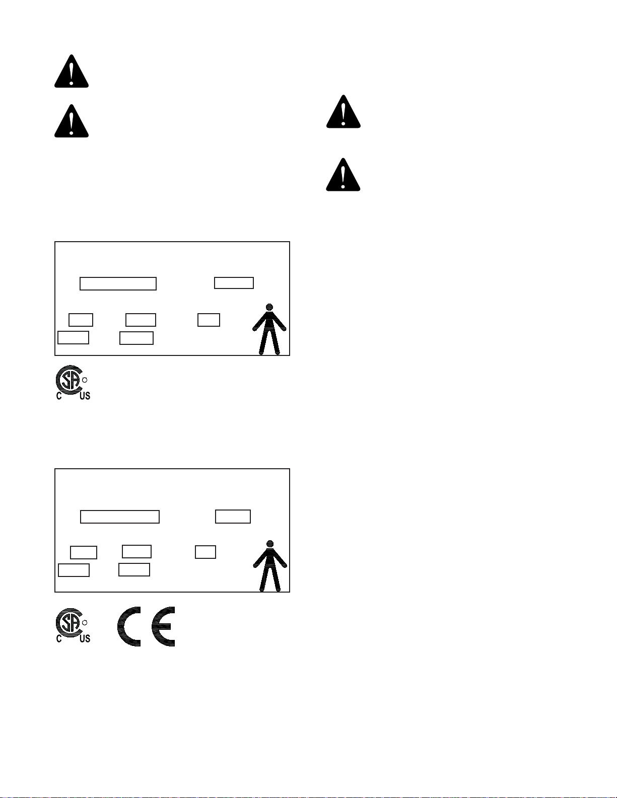
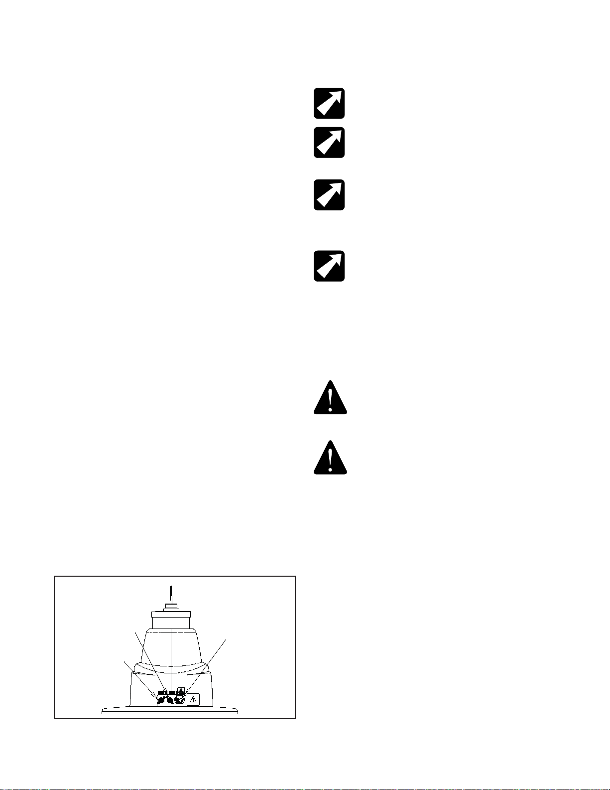
2.2.2. Power Receptacle
2.2.2.1. Locate the footswitch assembly, chair control
cable, and the power cord assembly. Refer to figure 1 for
receptacle location and attach all cables.
2.2.2.2. To disconnect power to Chair unplug power cord
from Instrument Stand or from wall receptacle.
NOTE: Outlet wires are hot.
NOTE : Les fils de sortie sont chaud
NOTE: If this chair is purchased in conjunction
with a Reliance® instrument stand, the chair control
cable supplied will provide proper operation. Refer
to the instrument stand manual for connection to
the stand.
NOTE: Si cette présidence est achetée
conjointement avec un gabarit d’instrument de
Reliance®, le câble de commande de présidence
fourni fournira le fonctionnement approprié. Référez
le manuel de gabarit d’instrument pour la connexion
au gabarit.
3. OPERATION
CAUTION- Caution should be taken to observe
that there are no obstructions (instruments,
trays, or tables) to impede the movement of
the chair.
ATTENTION- L’attention devrait être prise
pour constater qu’il n’y a aucune obstruction
(instruments, magasins, ou tables) pour
entraver le mouvement de la présidence.
Each time main power is applied to the chair, the circuit
board inside the chair will respond with a one second
beep. The beep indicates the electronics are functioning
properly.
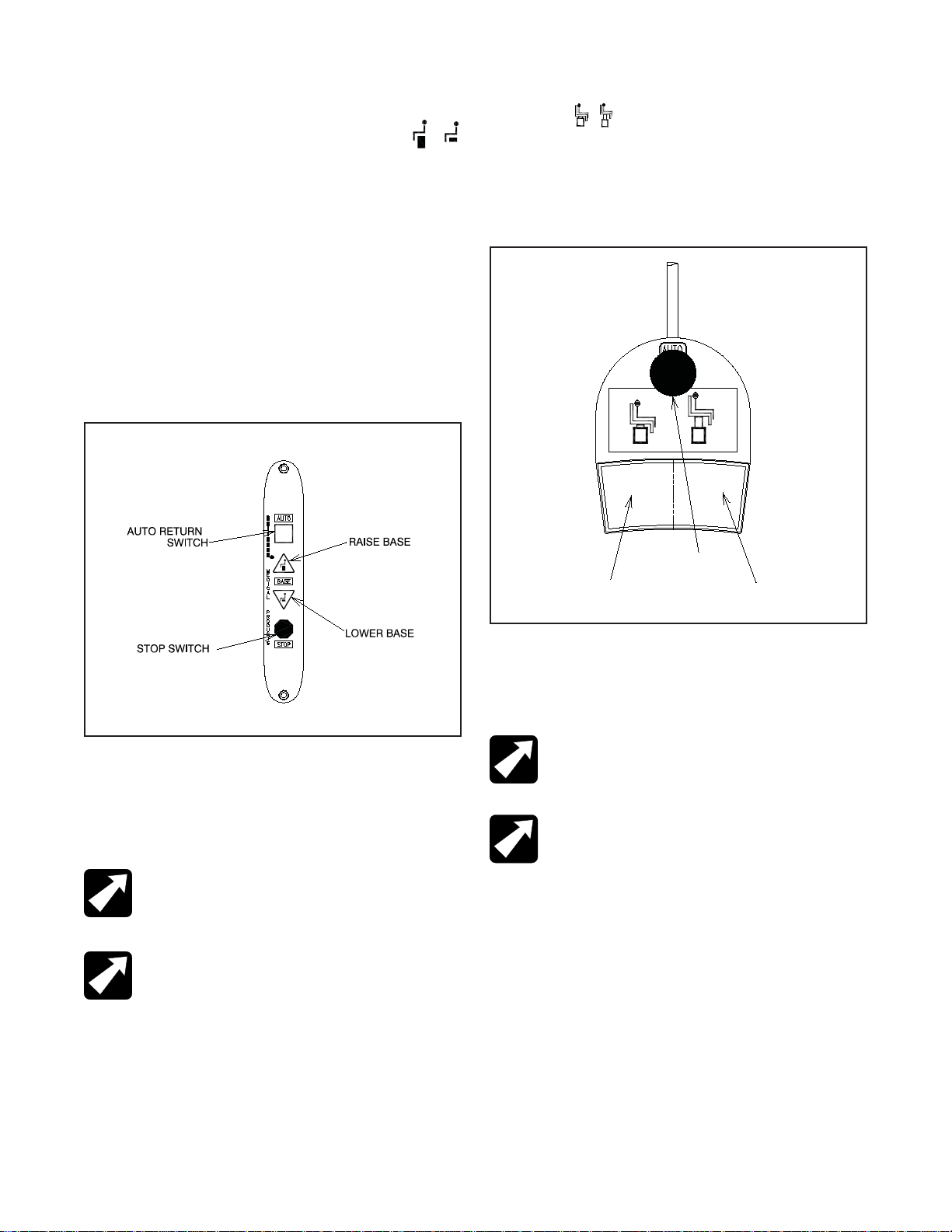
3.1. Stop Switch
3.1.1. Depressing the STOP switch on either side of the
chair back will STOP ALL movement of the chair. The STOP
switch is shaped like a stop sign, and may be either RED or
ORANGE in color. It is located above the text “STOP”. (Refer
to Figure 2).
FIGURE 1
BASE
Power Cord &
Fusedrawer
Footswitch
Cable
Chair Control
Cable
IN-FXM920 7