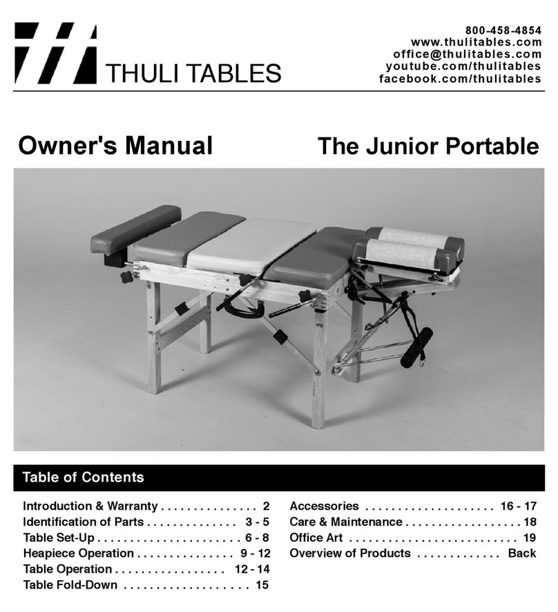
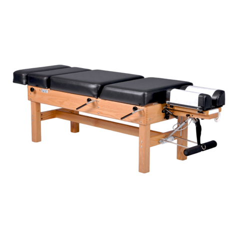
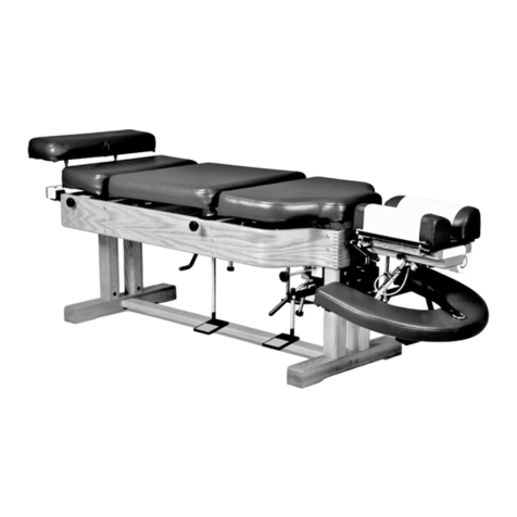
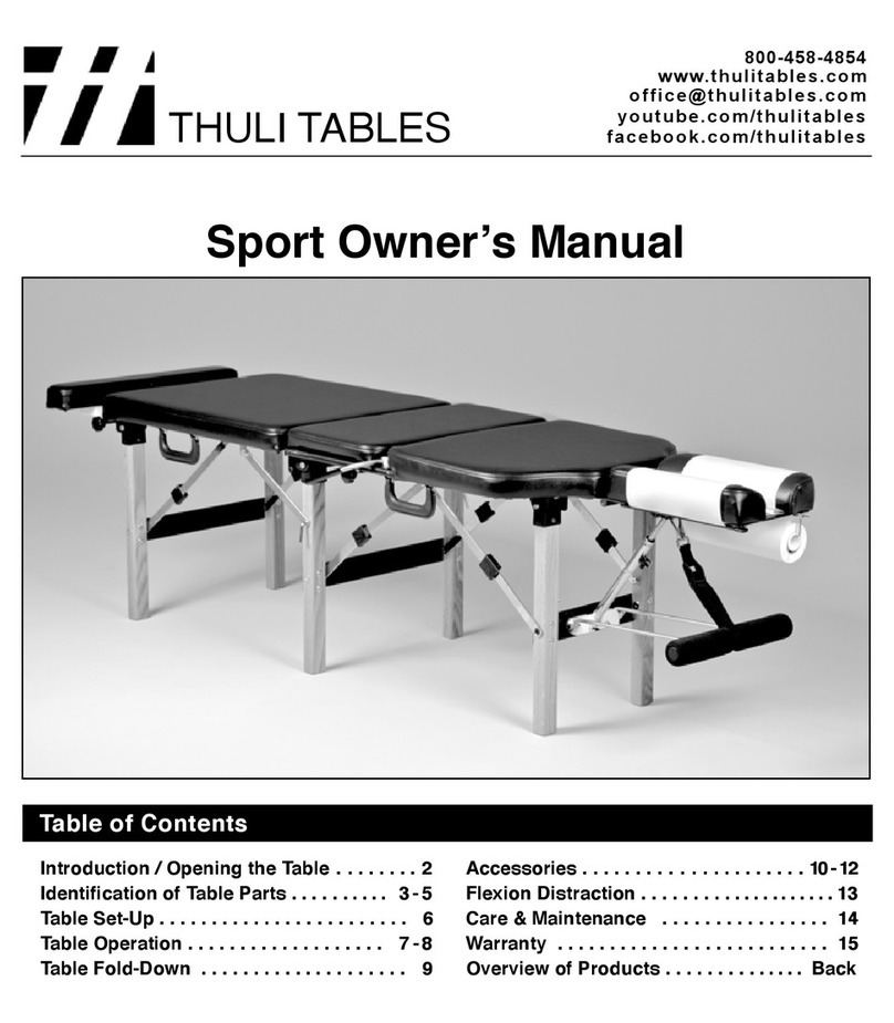
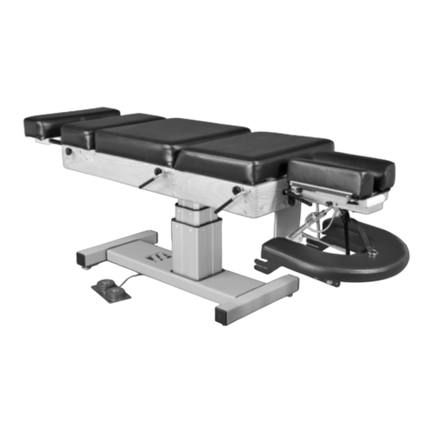
Thuli Tables Tour User manual

Tour Owner's Manual
TABLE OF CONTENTS
Table of Contents
Introduction . . . . . . . . . . . . . . . . . . . . . . . . . 2
Summary of Set-Up & Fold-Down . . . . . . . 2
Identication of Parts . . . . . . . . . . . . . . 3 - 6
Table Set-Up . . . . . . . . . . . . . . . . . . . . . 7 - 11
Heapiece Operation . . . . . . . . . . . . . . 11 - 14
Table Operation . . . . . . . . . . . . . . . . . 14 - 17
Table Fold-Down . . . . . . . . . . . . . . . . 18 - 19
Accessories . . . . . . . . . . . . . . . . . . . . 20 - 23
Flexion Distraction & Lateral Flexion . . . 24
Elevating Conversion Base . . . . . . . . . . . 25
Care & Maintenance . . . . . . . . . . . . . . 26 - 27
Warranty . . . . . . . . . . . . . . . . . . . . . . . . . . . 27
Overview of Products . . . . . . . . . . . . . Back
THULI TABLES
www.thulitables.com
youtube.com/thulitables
800-458-4854
facebook.com/thulitables

2
1. Open the table (pg 7)
2. Remove headpiece from storage, engage T-bar
and attach headpiece (pgs 7-8)
3. Erect front legs (pg 8)
4. Attach piston to headpiece (pg 8)
5. Release thoracic section (pg 9)
6. Erect middle legs & attach support braces (pg 9)
7. Erect back legs (pg 9)
SET-UP (pgs 7-9): Begin at the headpiece and progress toward the ankle rest.
Introduction 2
Table Set-Up & Fold-Down: Quick Reference
FOLD-DOWN (pgs 18-19): Reverse the set-up sequence above. Begin at the ankle rest and progress toward the headpiece.
Fold the front half of the table onto to the back half.
Rick Thuli, D.C.
President
Sincerely,
We are pleased to provide you with a chiropractic adjusting table that is elegant,
versatile and engineered with precision. It has been thoroughly inspected and
tested right down to the smallest detail before leaving our shop. We are
condent that it will provide you with many years of reliable service.
Please take the time to read this manual carefully. It will familiarize you with
the table and instruct you on its proper operation and maintenance.
If you have any questions or comments, please contact us.
Thank you for your purchase of a Tour portable table.

3
Pelvic Section
Caudal Section
Thoracic Section
Prone Arm Rest
Pin to close table and
attach headpiece
Caudal Cocking Lever
&Tension Control Rod
Pelvic Cocking Lever
& Tension Control
Rod
Thoracic Cocking Lever
&Tension Control Rod
Closing Block
Ankle Rest
Locking Knob
Mid-Leg
Support Brace
Headpiece
Bracket
Folding
Support Brace
(Left)
Identification of Table Parts 3
Piston
(adjustable)

4
Folding
Support Brace
(Left)
Folding
Support Brace
(Right)
Front Legs
Piston
Remote Control
Lever
Thoracic
Slant Bar
Prone Arm Rest
Pelvic Drop
Mechanism
Thoracic Cocking Lever
& Tension Control Rod
Brace Lock
Folding
Support Brace
(Right)
Thoracic
Hold-Down
Headpiece
Mount Bracket
Pin to close table and
attach headpiece
Mid Legs
Pelvic Cocking Lever
& Tension Control Rod
Thoracic Drop
Mechanism
Identification of Table Parts (folded position) 4

5
Hinge Pin for
Separating Table
Joining Hinge
Brace
Lock
Folding
Support Brace
(Right)
Remote Control
Slot
Joining Hinge Mid-Leg
Support Brace
Headpiece
Cocking Lever
Headpiece
Locking Link
Headpiece
Raising Lever
Caudal Drop
Mechanism
Caudal Cocking Lever
& Tension Control Rod
Paper Tear-Off Bar
Closing Block
Paper Hanger
Slot for
Headpiece Piston
Headpiece Tension
Control Knob
Headpiece
Slide Block
Identification of Table Parts (folded position) 5
Headpiece
Paper

6
Pivot Block
Paper Hanger
Remote Control Lever
Piston Head
Adjustable Buckle for
Prone Arm Rest
Flexion /Extension Piston
Prone Arm Rest
Lowering Lever
T-Bar
Cocking Lever
Straight Drop/
Forward Motion Knob
Remote Control Cable
Headpiece Mounting
Bracket (two holes)
Piston Pin
Slide Block
Tension Control Knob
(not visible)
Paper Hold-Down Wire
Paper Tear-Off Bar
Pin to close table &
attach headpiece
Pivot Pin
Identification of Headpiece Parts 6

7
OPEN THE TABLE
1. Position yourself on the handle side of
the table. Lay the table onto its cushions
so that the Thuli logo is upside down.
2. Remove the pin from the metal bracket.
Open the table by grasping one of the
carrying handles.
3. Set the pin on the oor at the left end
of the table. You will use this pin to
attach the headpiece.
1. Unfasten the Velcro strap and remove the headpiece from its
storage position and place on its cushions.
Note: The strap is not included on Tours with Flexion Distraction.
2. Lift the slide block by grasping the lowering lever and raising
it to a 45 degree angle.
3. Grasp the end of the T-bar with your other hand. Insert it
into the hole in the locking link of the slide block.
4. Lower the slide block to a closed position by applying counter
clockwise (downward) torque to the lowering lever.
HEADPIECE ATTACHMENT
Begin at the headpiece end and progress
toward the ankle rest:
5. To attach the headpiece to the table, line up the hole of the
slide block with the hole of the mounting bracket closest to
the cushions. Insert the pin with a twisting motion.
Note: If you are using the Comfort Pillow, the slide block
will come with a white plastic attachment. Line it up with the
holes of the mounting bracket farthest from the cushions.
Insert the pin with a twisting motion.
Table Set-Up 7
HEADPIECE ATTACHMENT (cont.)

8
HEADPIECE ATTACHMENT (cont.)
2. Raise the front legs from their folded position by grasping
the horizontal crosspiece.
3. Straighten the folding leg support braces and lock them into
place by sliding the black brace locks over the brace joints.
Note: If the brace lock falls down off of the brace joint,
slide the lock back over the joint and exert a slight pressure
perpendicular to the brace at the brace lock. This will provide
sufcient friction to keep the brace lock in place.
4. Swing the headpiece exion/extension piston down toward the
off-centered slot in the slide block.
5. Remove the piston pin from the slide block and raise the front
end of the headpiece to allow the piston to engage in the
off-centered slot. Note: Operating the remote control lever
will allow you to rotate the piston head to align with the
off-centered slot.
6. Attach the exion/extension piston to the slide block by visually
lining up the holes and re-inserting the piston pin.
6. Before raising the front legs from their folded position,
disengage the piston head from its locked position. Squeeze
the remote control lever and retract the piston head from the
hole in the frame.
NEED PHOTO
FRONT LEG SET-UP
Table Set-Up 8
FRONT LEG SET-UP (cont.) FRONT LEG SET-UP (cont.)

9
BACK LEG SET-UP
Swing the two mid-leg support braces up from the back
section of the table and attach them to the middle legs:
Line up the hole in the brace with the brass insert in the middle
leg. Push the mid-leg pin through the brace from the inside of
the leg until the ball (on the end of the pin) is completely
engaged through the brace.
1. Raise the back legs and lock the brace joints into place in the
same fashion as the front and mid-legs.
2. Reattach the Velcro strap through its metal loop.
3. Remove the headpiece paper from storage under the elastic strap.
MID-LEG SUPPORT BRACES
2. Release the Velcro-secured thoracic section.
3. Raise the middle egs by grasping the horizontal crosspiece.
4. Before the brace joints are fully straightened, slide the black
brace locks up toward the brace joints, then straighten the braces
and lock them into place. This step prevents the brace locks
from becoming bound between the middle and front leg brace
joints and is necessary only when setting up the middle legs.
THORACIC RELEASE & MID-LEG SET-UP
1. Install the black remote control lever into the bottom of the
slide block by inserting the cable into the narrow slot and tilt
the cable end of the lever into the slot until it snaps into place.
Note the milled nger recess for later removal of this lever
when folding up the table. Operating this lever will allow the
headpiece to lay ush with the table cushions.
Table Set-Up 9
REMOTE CONTROL LEVER

10
GAS SPRING INSTALLATION (cont.)
Insert the base end mount of the black gas spring in to the slot in
the aluminum mount block which is attached to the cross brace
of the front legs. Do this by pulling outward on the white handled
spring pin, inserting the gas spring base end tab and then releasing
the white handled spring pin until it engages in the tab.
GAS SPRING INSTALLATION (cont.)
Repeat previous step on the operating end of the black gas spring
where it attaches to the abdominal cushion. You may need to
pull up or push down slightly on the abdominal cushion by
grasping the aluminum mount block to help with alignment so
that the engaging spring pin slides in easily.
GAS SPRING INSTALLATION
GAS SPRING & CONTROL LEVER REMOVAL
Remove the Abdominal Swing-Away gas spring and control lever
from its storage location. Note that the control lever is positioned
and attached by a magnetic latch.
Slide the black control lever housing onto the front folding leg
support brace and position it to come into contact with the black
poly lock. It will be held in place with an internal magnet.
Abdominal Swing-Away Set-Up (optional feature) 10

11
1. Install a standard 8.5" roll of headpiece
paper, as shown.
2. Raise the paper hold-down wire and
tear-off bar. Advance the paper and tuck
it between the cushions.
3. Lower the hold-down wire between the
cushions, lower the tear-off bar and tear
off excess paper. See step 5.
4. To advance the headpiece paper, raise
the tear-off bar, hold your nger on the
paper hold-down wire and pull the
paper across the cushions. Pulling the
paper in an upward direction will
reduce friction making it easier to pull.
CORRECT TABLE POSITIONING BEFORE SETTING UPRIGHT
5. To tear off used headpiece paper, use an
upward motion while holding down the
tear-off bar.
SET THE TABLE UPRIGHT: Tilt the table away from you and onto its feet.
HEADPIECE PAPER
Table Set-Up & Headpiece Operation 11

12
VERTICAL ELEVATION
VERTICAL LOWERING
2. Raise the front end of the headpiece by
operating the remote control lever.
1. Lower the front end of the headpiece by
operating the remote control lever, as in
exing or extending the headpiece.
2. Lower the back end of the headpiece by
lifting the headpiece lowering lever
rmly with one hand while gently lowering
the back end of the headpiece with your
other hand.
FLEXION AND EXTENSION
3. With practice, steps 1 and 2 can be
combined to vertically raise the headpiece
in one smooth motion.
IMPORTANT
Advise your patient before changing the
position of the headpiece. This is especially
important when lowering the back end of the
headpiece (step 2). Failure to do so may
result in its sudden drop, causing possible
alarm to the patient.
Flex and extend the headpiece by grasping
the front end of the headpiece and operating
the remote control lever on the underside of
the headpiece with your ngertips.
Headpiece Operation 12
1. Raise the back end of the headpiece
by lifting the red grip of the cocking
lever (without operating the lever).
Caution: Do not grasp the cushions to
raise the back end, which could stretch
and damage the small springs.

13
HEADPIECE CUSHION ADJUSTABILITY
HEADPIECE PORTABILITY
The Tour headpiece can easily be detached and used as a
portable headpiece for cervical adjusting. Simply lift the
back end of the headpiece until the T-bar disengages from
the locking link. Snap the T-bar into the receiver clip on
the underside of the headpiece for storage. Remove the
pivot pin from the front of the headpiece. Place the head-
piece on a stable surface. You can use the straight drop
and forward motion drops. Please note that it will not raise
up/down or ex/extend when not mounted to the table.
Neutral position. Narrower position for smaller faces
(eg children).
Wider position takes pressure off of
the patient's eyes.
The headpiece cushions are adjustable in width for patient comfort. Firmly pull up on the front end of each headpiece cushion and
move in (one or two notches) or out (one or two notches) to the desired position. Secure cushions by engaging locating pins into
notches provided.
Headpiece Operation 13
Note: A stabilization base for the portable headpiece is
available from Thuli Tables to distribute the drop forces
over a broader surface.

14
DROP OPERATION AND TENSION SETTING
1. Advise your patient prior to setting the tension.
2. With the patient on the table, cock the drop section with an
upward motion of the cocking lever. There must be sufcient
tension on the drop to hold the patient's head or body weight.
3. Decrease the tension control knob by turning it
counter-clockwise until the section drops.
4. Increase the tension by turning the tension control knob
clockwise 3-4 half turns. As a general rule, the drop is now
set for the patient's weight, which may vary according to the
practitioner's preference.
STRAIGHT DROP FORWARD MOTION DROP
Knob pulled out BEFORE cocking
Headpiece & Table Operation 14
MAXIMIZING FACIAL COMFORT
For patients sensitive to pressure on the eyes, slightly raise the
back end of the headpiece. This will take pressure off of the
eyes, supporting the weight of the head at the mandible and
zygomatic arches. This maneuver, in combination with slight
exing of the headpiece, will provide optimal facial comfort for
some patients.
Knob pushed in BEFORE cocking
The drops on the headpiece and table have adjustable tension and
cock with an upward movement of the cocking lever. Following
is a general guideline for setting the tension.
PRIOR to cocking the headpiece, set for straight drop by pulling
out the headpiece straight drop/forward motion knob until you
feel it is “set” into position. This will be just short of coming
into contact with the cocking bar. If you pull the knob out too
far, simply push it back in.
PRIOR to cocking the headpiece, set for forward motion drop
by pushing in the headpiece straight drop/forward motion knob.
Cock the headpiece with an upward motion on the headpiece cocking lever.
Please note: Be sure to change the headpiece drop function
before cocking the headpiece to prevent an ineffective drop and
damage to the drop mechanism.
Set the desired tension by turning the tension control knob clockwise (increasing tension) or counterclockwise (decreasing tension).

15
Cervical palpation and adjusting. Anterior thoracic adjusting.
THORACIC SLANT SECTION
When using the thoracic drop, the patient should be positioned sufciently
forward with arms outstretched and wrists supported by the adjustable
Prone Arm Rest. This will insure that the patient's arm will not be pinched
between the thoracic section and the table frame.
THORACIC DROP & ADJUSTABLE PRONE ARM REST PELVIC DROP
Proper prone positioning on the pelvic drop
section should have the patient's anterior
superior iliac spine (ASIS) at the juncture
of the pelvic and thoracic sections.
Table Operation 15
Release the thoracic section by unfastening the Velcro.
Swing down the metal slant bar and engage the ends into the holes in the leg blocks.
Note: Release the thoracic section prior to raising or using the drop.

16
Use of the caudal drop section for supine adjusting of the pelvis
when used in conjunction with the raised thoracic slant section.
Side posture support of the patient's head for lumbo-pelvic
adjusting or toggle recoil adjusting. Shown with Headpiece
Extension Pillow.
CAUDAL DROP SIDE POSTURE POSITIONING
Table Operation 16
ANKLE REST EXTENSION
The ankle rest can be extended up to 8" and locked into position
by tightening the tension knob on the side of the table. Shorter
patients can drop their feet into the recess created by the extended
ankle rest.

17 Abdominal Swing-Away Operation (optional feature) 17
STORAGE OF CHEST CUSHIONPLACEMENT OF CHEST CUSHION
Firm Chest Cushion
This cushion has a foam density that matches the rmness of
the rest of the table. It is ideal for thoracic drop adjusting.
Soft Chest Cushion
INTERCHANGEABLE CHEST CUSHIONS
This cushion provides a combination of soft foam in the breast
area and rmer foam surrounding, insuring adequate thoracic
support when the patient is lying prone or supine.
When not using the chest cushion, consider:
1. Storing it in the space vacated by the extended
ankle rest section (photo above).
2. Use it as a bolster under the patient’s ankles when
lying prone.
3. Use it as a bolster under the patient’s knees when
lying supine.
The chest cushions are attached by four magnets.
To remove the cushion, simply grasp at both sides
and twist (toward the headpiece) with a lifting
motion. The cushion is held in correct position by
aligning the two holes on the underside of the chest
cushion with the two nickel-plated acorn nuts on the
thoraic drop plate.
ABDOMINAL SWING-AWAY
Activate the lever on the side of the table while
depressing the abdominal section. This can be
done before the patient lays on the table or while
the patient is on the table. Adjust the positon of
the swing-away section to the patient’s comfort.
The Abdominal Swing-Away offers prone comfort
to pregnant patients or to those with “a little extra
around the middle.”

18
HEADPIECE DETACHMENT & STORAGE
1. Return the ankle rest extension, drop sections and headpiece to their neutral positions and remove the headpiece paper roll from
the paper holder. Reattach the paper roll holder to the headpiece.
2. Turn the table upside down onto its cushions. Stand on the side opposite the carrying handles and cocking levers, and tip the
table toward you onto its side, then onto its cushions. You will now be able to proceed with folding the table for transport,
working from the carrying handle/cocking bar side of the table. See page 18 for the Abdominal Swing-Away fold down.
3. Fold the back legs down into the table. Be sure to slide the black brace locks completely down to where the braces are riveted to
the table frame.
4. Push in the mid-leg pins to disengage the mid-leg support braces, swing the braces into the back section of the table and
then push the mid-leg pins completely in until they are ush with the leg, allowing for clearance when folding up the middle legs.
5. Fold the middle legs into the table in the same manner as for the back legs.
6. Secure the thoracic section in place with the Velcro closure.
16. Unfasten the black Velcro strap located in the back section of the table.
Note: Strap is not included on Tours with Flexion Distraction.
17. Store the headpiece, cushions down, into the UPPER RIGHT
HAND CORNER of the back section of the table and secure into
place with the Velcro strap. The headpiece paper holder may remain
in place attached to the headpiece, laying on top of the side rail.
18. Store the headpiece paper roll under the elastic strap located to the
left of the stored headpiece.
HEADPIECE STORAGE
7. Remove the remote control lever, utilizing the nger slot provided.
8. Remove the headpiece piston pin from the side of the headpiece to disconnect
the exion/extension piston from the slide block.
9. Retract the piston rod completely into its cylinder by operating the remote
control lever with one hand while pushing the rod in with the other. (see photo)
10. Store the headpiece piston pin in the hole from which it was removed.
11. Fold the front legs into their storage position.
12. Swing the prone arm rest, along with the piston, all the way into the table,
tucking the remote lever with attached cable under the two metal bars of the
prone arm rest. Engage piston into hole in frame.
13. Detach the headpiece from the table by removing the closing/mounting pin
with a twisting motion and set it on the oor. You will use this pin to secure
the two table halves together when folded.
14. Slide the headpiece out from between the headpiece mounting bracket.
15. Disengage the T-bar from the slide block by holding the headpiece side rail
down with one hand while lifting the slide block with the other.
Store the shaft of the T-bar in the clip on the inside headpiece strap.
Fold the slide block of the headpiece back down over the T-bar.
WHEN FOLDING THE TABLE, REVERSE THE SEQUENCE OF TABLE SET-UP.
BEGIN AT THE ANKLE REST AND PROGRESS TOWARD THE HEADPIECE.
Table Fold-Down 18

19
1. Fold the front section (i.e. the section without the stored headpiece) onto the back
section of the table. This will prevent the headpiece from shifting out of position during
table closure. Make certain that the carrying handles do not obstruct closure. The spring-
loaded headpiece lowering lever will be oriented somewhat upward in its properly stored
position and will automatically collapse when closing the table. This is normal.
CLOSING THE TABLE
2. Secure the two table halves together by inserting the pin through the Thuli closing block
and the headpiece mount bracket with a twisting mtion.
3. Set the table upright onto its four protective bumpers which offer protection to the vinyl
when the table is folded for transport.
NEVER USE FORCE to close the table or to fold down any of the table's
components, as this may indicate improper positioning of internal parts.
Checklist to insure unobstructed table closure:
a. Carrying handle of front section must clear carrying
handle of back section when closing table.
b. Flexion/extension piston must be completely in the hole of
the table frame.
c. Black leg support brace locks must be pushed down all the
way to where the braces are riveted to the frame.
d. The headpiece must be stored in the upper right hand
corner of the back section of the table.
Table Fold-Down 19
After Step 2 on page 17: Detatch and store the gas spring and control lever in the reverse sequence that you used in set up.
NOTE: The “operating end” of the gas spring must be positioned with the cable attachment/lever apparatus pointing upward
(see photo 1, page 10). The black cylinder of the gas spring should be snapped into the spring clamps and positioned to
remove all slack from the gray cable sheath. Attention to this positioning will allow the two cushions of the headpiece to
straddle the apparatus when it is stored.
ABDOMINAL SWING-AWAY FOLD-DOWN (optional feature)

20
The Side Arm Rests provide an 8"-14" wider table surface in the
thoracic region for supporting the patient's arms whether prone
or supine. To install, slide the two rods of the Side Arm Rests
into the pre-drilled holes in the table frame. The Side Arm Rests
must be removed before folding up the table or when using
the pelvic and/or thoracic drop sections. They must be ordered
at the time of original table purchase and can not be added at a
later time.
SIDE ARM RESTS
The Height Raising Legs offer a second pre-determined height
to the Tour, up to 30". Please note that they are not variable in
height and must be removed when folding the table.
HEIGHT RAISING LEGS
Accessories 20
CAUTION: Remove the Side Arm Rests BEFORE the patient
gets off of the table. The weight of a person on the Side Arm
Rests can result in a cracked table frame.
CRESCENT ARM REST
The Crescent Arm Rest provides additional forearm support in
the prone position and is easily adjustable in height.
The Height Raising Legs can be added at a later time (some
installation required).
Can be added at anytime.
To attach, simply slide both slotted ends of the bracket onto
the rivets located on the inside of the front legs and push down
until it snaps into place on top of the standard Prone Arm Rest.
PRONE ARM REST SHIELDS
Nonporous and durable plastic
shields slip over the prone arm rest
grips. Easy to sanitize.
Table of contents
Other Thuli Tables Medical Equipment manuals