Net2Edge PacketBand PB-ISDN Series User manual

QSG
Quick Start Guide: PB-ISDN
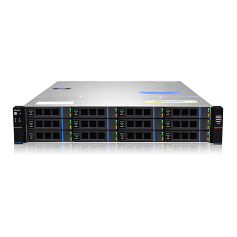
PacketBand ISDN Chassis

QSG | Quick Start Guide: PB-ISDN
| www.net2edge.com
2
Trademarks
All trademarks and registered trademarks are the property of their respective owners.
Copyright Notice/Restrictions
Copyright © 2016 Net2Edge Limited all rights reserved.
No part of this work may be reproduced or used in any form or by any means (graphic,
electronic or mechanical) without written permission from Net2Edge.
The information contained herein is confidential property of Net2Edge Limited. The use,
copying, transfer or disclosure of such information is prohibited except by express
written agreement with Net2Edge Limited.
Revision History
Rev
Date
Description
2.0
5th September 2016
Rebranding and formatting changes

QSG | Quick Start Guide: PB-ISDN
| www.net2edge.com
3
Contents
Contents
Trademarks.................................................................................................. 2
Copyright Notice/Restrictions ................................................................... 2
Revision History........................................................................................... 2
Contents....................................................................................................... 3
1. Introduction ........................................................................................ 4
2. Applications ........................................................................................ 4
3. Features .............................................................................................. 4
4. Getting Started ................................................................................... 5
4.1 Standard Accessories .......................................................................................... 5
4.2. Optional Accessories ........................................................................................... 5
4.3 Making Connections ............................................................................................ 5
4.4 Installing DbManager ........................................................................................... 6
5. Configuring PacketBand ISDN Chassis ........................................... 7
5.1 Connecting to the PacketBand ISDN Chassis................................................... 7
5.2 Notes on configuring the PacketBand ISDN Chassis ....................................... 9
5.3 Device Settings ..................................................................................................... 9
5.4 Clock Sources..................................................................................................... 10
5.5 PRI Ports ............................................................................................................. 10
5.6 Configuring Routing Profiles ............................................................................. 11
5.7 Prioritizing Routing Profiles............................................................................... 12
5.8 Link Configuration .............................................................................................. 13
5.9 Using Groups ...................................................................................................... 14
5.10 Finishing Configuration...................................................................................... 14
5.11 Additional Resources ......................................................................................... 14
5. Contacts............................................................................................ 15

QSG | Quick Start Guide: PB-ISDN
| www.net2edge.com
4
1. Introduction
This document is a basic guide for configuring a new Net2Edge PacketBand ISDN. A full
User Manual for configuring all settings on the unit is supplied on the DbManager
Installation Disk.
2. Applications
The PacketBand ISDN range allows the delivery of synchronous ISDN, across
asynchronous IP networks. The product range covers both switched ISDN applications
and unswitched 'nailed' circuits. PacketBand will packetize traffic for transport across
the IP network and transparently depacketise it at a remote site. The traffic will then be
played out to the data interfaces.
PacketBand ISDN must be used as a two-ended solution, and an existing system can
easily be expanded with more PacketBand ISDN units to allow links to new sites and
devices.
3. Features
The PacketBand ISDN Chassis is available to support either 8, 16 or 32 PRIs. Each
product has the following features:
• 8, 16 or 32 PRI (E1 / T1 ports)
• 2 x SFP cages
• 2 x RJ45 UTP ports
• 1 x RJ12 asynchronous control port
• 1 x RJ11 alarm port
• 2 x RJ45 external clock inputs
• 2 x BNC external clock inputs
• 1 or 2 PSUs (AC or DC)

QSG | Quick Start Guide: PB-ISDN
| www.net2edge.com
5
4. Getting Started
This section will describe how to make the physical connections between PacketBand
ISDN Chassis and the other system devices, and install the Net2Edge management
application, DbManager.
4.1 Standard Accessories
The following accessories are supplied with the PacketBand ISDN:
Item
Description
DbManager CD
Installable DbManager application, technical documents and
manuals
Controller Cable
Management cable. Connects to the
PacketBand ISDN Chassis’ Terminal
port
Cable Spec
RJ12
DB9S
Pin
Function
Pin
1
Rx
3
2
Tx
2
3
Gnd
5
IEC Mains Cable
Connects PacketBand ISDN Chassis to the mains supply
4.2. Optional Accessories
The following items can be ordered separately:
ISDN Cables
Cables to connect the PacketBand ISDN Chassis to a
CPE or network. Please see the full manual for
specifications of all Net2Edge cables
SFP Modules and Cables
Please see the PacketBand ISDN Chassis user manual
for instructions and precautions to take when using SFP
modules
4.3 Making Connections
First, connect the ISDN cables to PacketBand ISDN Chassis followed by the Terminal
Port management cable (if required), PKT Port cable and lastly the Mains cable. If the
unit has a DC power supply connection, use the screw terminals to connect the DC
power source.
If the unit has a DC power supply connection, use the screw terminals to connect the
DC power source.

QSG | Quick Start Guide: PB-ISDN
| www.net2edge.com
6
Warning: The -48VDC power terminals are marked 0V, -48V, and GND.
Net2Edge -48VDC products are designed for use with negative voltage DC
supplies, and therefore expect the positive voltage to be connected to the 0V
terminal, and the negative connected to -48V. Please be sure about the polarity
of this connection before connecting power to the terminals. Units which have a
positive +24VDC power source will be marked +24VDC, 0V and GND
respectively. Please ensure that the positive connection is made on the +24VDC
terminal.
4.4 Installing DbManager
DbManager is required in order to monitor and manage the PacketBand ISDN Chassis.
Management can be made using the Terminal (serial) port, or using TCP/IP over a LAN
or WAN. DbManager is installed using the CD provided with product or can be
downloaded from the Net2Edge Website: www.net2edge.com
1. Insert the DbManager Installation Disk into the drive of the PC which will be used
for management of PacketBand ISDN.
2. InstallShield Wizard will start up. Follow the steps to install DbManager.
3. Serial Number – Enter the Serial Number on the case of the DbManager Disk.
N.B.: DbManager is supplied as a 'Lite' version by default. This allows configuration
and monitoring of devices, but only allows configuration of a single device node and
a single user account. To use DbManager in 'Lite' mode, do not enter a serial
number during installation. Please see the full DbManager User Manual for more
information on configuring and using DbManager.
Warning: If an older version of DbManager is already installed on the management
PC, it is necessary to update to the version supplied on the new DbManager CD.
This can be done by consulting the ‘Upgrade’ folder on the DbManager CD. The
‘readme.txt’ file explains how to upgrade to the new DbManager without reinstalling
the program.

QSG | Quick Start Guide: PB-ISDN
| www.net2edge.com
7
5. Configuring PacketBand ISDN Chassis
Follow these steps to connect to PacketBand ISDN Chassis with DbManager and
configure the unit for use.
Configuration of PacketBand ISDN Chassis is carried out by setting up DbManager to
make a management connection, and then setting up the elements of PacketBand ISDN
Chassis in this order:
Device Settings
The unit-specific settings of the PacketBand ISDN
Chassis such as the IP Address and Identifier
Clock Sources
configure which interface PacketBand ISDN Chassis is
to take synchronisation clock from a network, or
recovered clock from another PacketBand ISDN
Chassis
ISDN Ports
Each ISDN port can be individually configured with the
correct settings to interface with another device or
network
Link Configuration
Configure settings to carry ISDN channels across a
PSN between PacketBand ISDN units
Call Routing
Configure routes for the traffic PacketBand ISDN
Chassis will pass between connected devices and
networks
5.1 Connecting to the PacketBand ISDN Chassis
1. Start up the DbManager Application
2. Login as Super User (no password required)
3. Four windows will be displayed:
Map
A network map showing Nodes
and Links between Net2Edge
devices
Terminal
A view of the communications
between DbManager and
PacketBand ISDN
Event History
All events which occur while
connected to PacketBand ISDN
Outstanding Events
Current Events

QSG | Quick Start Guide: PB-ISDN
| www.net2edge.com
8
4. Select View Properties Terminal from the DbManager toolbar.
5. Choose the COM port which is in use. Leave the Serial Port Rate at the
default setting of 19200bps. Click OK.
6. Select the Devices in World window and double click the Device node
7. The Connected to Device window should appear, showing the front and rear
panels of PacketBand ISDN. If it does not, check the COM port settings and
try again.
Warning: If management via the Terminal port is not possible, it could be that
the management PC has another application running which uses the COM
ports of the PC. Even when some programs which use the COM ports are
closed down, other programs cannot access the COM ports. Rebooting the
PC is required in order to release the COM ports so that DbManager can use
them
If the PC and PacketBand ISDN Chassis are connected to the same LAN, management
is possible using TCP/IP. The PacketBand ISDN default IP settings are:
IP Address: 192.168.0.1
Subnet Mask: 255.255.0.0
Gateway: 0.0.0.0
To configure DbManager to access the PacketBand ISDN Chassis using TCP/IP, please
follow these steps:
1. Select View Properties Terminal Device IP Addresses from the DbManager
toolbar
2. 192.168.0.1 should already be configured. If using another IP address, Add it to
the list using the Add button
3. Click OK OK
4. Select the Devices in World window and double click the Device node
5. The Connected to Device window should appear, showing the front panel of
PacketBand ISDN.
The Device node can be made to connect to other IP addresses configured in the
Device IP Addresses list by right-clicking the node, selecting Properties and choosing
an IP address from the IP List.
Info: TCP/IP management requires TCP port 3001 (dec) to be open between the
management PC and PacketBand ISDN Chassis. Any switches, hubs or routers
must be configured to allow communication on this port in order to manage the
PacketBand ISDN Chassis via TCP/IP.

QSG | Quick Start Guide: PB-ISDN
| www.net2edge.com
9
A successful management connection will open up the Connected to Device window:
5.2 Notes on configuring the PacketBand ISDN Chassis
Uploading
Changes to the configuration can be made on each window and saved using the OK key
when exiting each window. When happy with the configuration, it must be uploaded to
the PacketBand ISDN for the new settings to come into effect.
To upload, go to File Upload and wait until the progress bar completes.
Saving Files
Configuration files can be saved in order to backup settings or copy settings across to
another unit. Once the configuration has been uploaded, go to File Save File and
choose a location where you wish to save the file. The file extension of any saved config
files is .dbc
Loading Files
Once connected to a unit, an existing configuration file can be loaded to the device. Go
to File Open File and navigate to the saved file. Click Open. Now the file must be
uploaded to PacketBand ISDN: Go to File Upload and wait until the progress bar
completes.
Warning: When loading existing configuration files to a unit, please ensure that
the correct configuration files are used for the unit type in use. PacketBand ISDN
Chassis configuration files are not compatible with other Net2Edge products.
5.3 Device Settings
This menu controls unit-specific features of the PacketBand ISDN such as the IP
Address, Identifier, Serial Number, Configuration Number, Time & Date and Event
Reporting. These features are all fully explained in the PacketBand ISDN Chassis User
Manual on the DbManager Installation Disk.

QSG | Quick Start Guide: PB-ISDN
| www.net2edge.com
10
5.4 Clock Sources
PacketBand ISDN Chassis must be configured to either receive clock from an ISDN
interface or generate clock internally. Different priorities can be set for each port, so if
one port is unavailable, PacketBand ISDN Chassis will clock from the next available port
in the Clock Source hierarchy
1. Select Clock Sources from the Terminal port menu.
2. Enter values into the table to denote the clocking priority of each interface on
PacketBand ISDN Chassis. The values which may be entered are as follows:
0
Interface Not Used
1-32
ISDN Ports
33-36
External Clock Ports (optional)
101-108
Logical Links 101-108
3. Click OK to save the setting.
Warning: Clock Sources must be configured correctly to ensure error-free
operation when PacketBand ISDN Chassis is connected to any other clock-
locked system or network. Please consult the full PacketBand ISDN manual if
unsure how to configure Clock Sources.
5.5 PRI Ports
All PRI ports are NT by default (connect to TE device). To use the ports as TE, each port
must be manually set to TE and a crossover cable must be used. Each port has a single
LED to show its status:
Flashing once/sec:
Layer 1 and 2 established
Flashing five times/sec:
Layer 1 established, trying to synchronize with Layer 2
On:
Calls active on interface
1. Click on an enabled PRI port.
2. The configuration settings for the port are displayed.
3. Configure the settings as required for the port.
4. Click OK to save the settings.

QSG | Quick Start Guide: PB-ISDN
| www.net2edge.com
11
5.6 Configuring Routing Profiles
It is strongly recommended that you draw a simple diagram showing the PacketBand
ISDN Chassis, its ISDN ports in use, the DDI numbers, and any local devices and the
number ranges used to access them. An example is shown below.
This example requires that the PacketBand ISDN-32s route calls as follows:
1. Route calls from the PSTN to the PBX
2. Route calls from the PBX to the PSTN
All of these actions can be catered for using Call Routing Profiles. A Call Routing Profile
is used to direct traffic from one port or group of ports to another, or to a Logical Link. A
Routing Profile has many options to control how calls are routed, but in this case and in
most applications the Routing Profile will consists of the following elements:
Name, Source, Destination
Click on the Terminal port and select Call Routing from the Drop-Down menu to
configure routing profiles for PacketBand ISDN Chassis.
1. The Call Routing Profiles List is displayed. This will show all Routing Profile
details when they are configured.
2. Select Add Profile and choose Add Routing Profile.
3. Name the profile and tick the Enable check-box.
4. Move the SOURCE PORTS radio button to Select and enter a source for
incoming calls. A source can be designated by entering a port number, port and
channel number or by using a Group of ports and/or channels:
To use a port:
Enter the port number (e.g. 1for PRI 1, 2 for PRI 2)
To use a port and
channel:
Enter the port number followed by a full stop and
then the channel number (e.g. 1.1 for PRI 1 channel
1, 2.2 for PRI 2 Channel 2)
To use a Group:
Configure a group and select it from the Drop-Down
menu
To use a Logical
Link:
Enter the Logical Link number (101 for Logical Link
101, 164 for Logical Link 164)

QSG | Quick Start Guide: PB-ISDN
| www.net2edge.com
12
5. Move the DESTINATION PORTS radio button to Select, and enter a destination
for calls in the same way as the SOURCE PORTS
6. Select the Incoming Numbers tab to choose numbers which Liberator will use to
route the calls.
Note: If no Incoming Numbers are configured (*/*), the PacketBand ISDN Chassis
will route all calls received on the Source ports to the Destination ports,
regardless of the DDI, CLI or SubAddress numbers of the call.
7. The DDI Listing defaults to */* which represents any number and any SubAddress
(Number/SubAddress).
8. Double click the */* to edit the number values. An entry of *1234/* would route
any call with a DDI ending in 1234 with any SubAddress. Right-clicking an
existing entry will present more options.
9. Enter a CLI value if required. This is entered in the same way as the DDI. The
default value; * will route calls with any CLI.
Note: More routing options may be used to configure complex routing profiles.
These are all explained in the PacketBand ISDN-32 manual on the DbManager
installation disk.
10. Click OK on the two active windows and the new routing profile will appear in the
Call Routing Profiles List.
11. Click Exit to return to the Connected to Device window.
5.7 Prioritizing Routing Profiles
The Call Routing Profiles List shows all configured Call Routing Profiles in order of
priority. These priorities can be rearranged to allow diverse routing possibilities. When
PacketBand ISDN Chassis receives a call, it will check each profile in order from the top
of the list for any routing parameters matching those of the call. It will route the call
based on the first matching profile.
1. Select Call Routing from the Terminal port Drop-Down menu.
2. All configured routing profiles are displayed.
3. Right click on a profile in the Type column to display options. The profile can be
promoted or demoted in the priority list. There are also options to edit and delete
the profile.

QSG | Quick Start Guide: PB-ISDN
| www.net2edge.com
13
This table shows the profiles which would be required to carry out the call routing
shown in the diagram above:
Profile
Number
Profile Name
Source
Primary
Destination
DDIs
0
PSTN to PBX
1
101
*/*
1
PBX to PSTN
101
1
*/*
The PacketBand ISDN Chassis will route any calls from the PSTN to PacketBand ISDN
Chassis via its Logical Link 101, and any calls from the PacketBand ISDN Chassis to the
PSTN. The PacketBand ISDN Chassis will have the following routing configuration:
Profile
Number
Profile Name
Source
Primary
Destination
DDIs
0
PBX to PSTN
101
1
*/*
1
PSTN to PBX
1
101
*/*
Calls can now be passed between the two PacketBand ISDN Chassis.
5.8 Link Configuration
The Link Configuration option is used to configure Logical Links between PacketBand
ISDN Chassis. Each Logical Link can carry up to 32 ISDN channels.
1. Click on Link Configuration
2. Select the first Logical Link; LL101
3. Tick the Enable checkbox
4. Enter the IP address of the remote PacketBand ISDN Chassis
Note: Each Logical Link can be configured with many settings for transport
across a Packet Switched Network. All of these options are described in the
PacketBand ISDN Chassis User Manual. The above settings are all that is
required to get a Logical Link running initially. A pair of PacketBand ISDN Chassis
working in a system should have identical Logical Link settings in order to pass
traffic across a PSN.

QSG | Quick Start Guide: PB-ISDN
| www.net2edge.com
14
5.9 Using Groups
When more than one port needs to be configured as a source or destination for calls, a
Group of ports can be set.
1. Select Add Group from the Add Routing Profile screen.
2. The Group Configuration screen is displayed.
3. Name the Group you wish to configure.
Note: The names of any Routing Profiles, Groups and Identifiers must not contain
the following characters: < > ~
4. Use the All and None buttons to add blocks of PRI and BRI ports to the Group,
or select individual channels from each port by using the tick-boxes.
5. Click OK to save the group.
6. The new Group will now appear in the SOURCE and DESTINATION drop-down
menus. Select this Group from the drop-down to use it in a Call Routing Profile.
5.10 Finishing Configuration
Note: Please remember to Upload when configuration of PacketBand ISDN
Chassis is complete. To upload, go to File Upload and wait until the progress
bar completes.
5.11 Additional Resources
All Net2Edge products and the DbManager application have their own User Manuals
which can be found in the 'Documents & Manuals' folder on the DbManager installation
disk or by registering at the Net2Edge website: www.net2edge.com
For help with a specific problem, please click on the On-Line Help icon on the website,

QSG | Quick Start Guide: PB-ISDN
| www.net2edge.com
15
5. Contacts
Corporate Headquarters
Net2Edge Limited
Kulite House
Stroudley Road
Basingstoke
RG24 8UG
United Kingdom
tel: +44 345 013 0030
www.net2edge.com
This manual suits for next models
1
Table of contents
