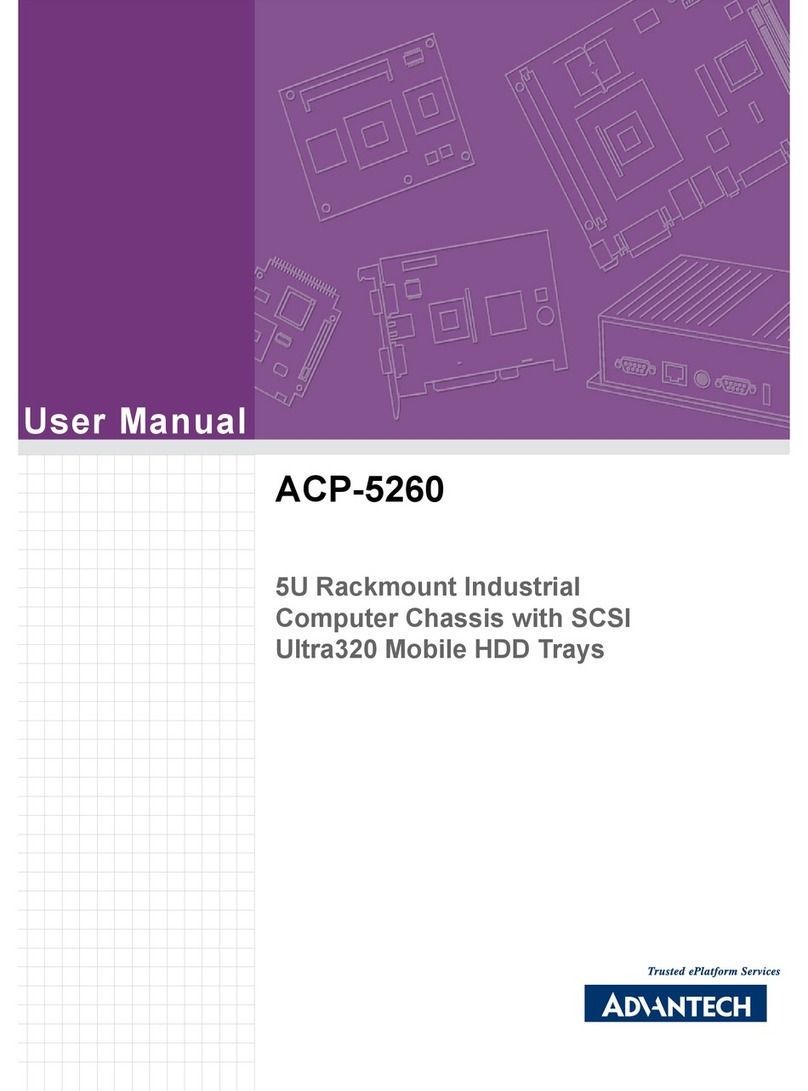
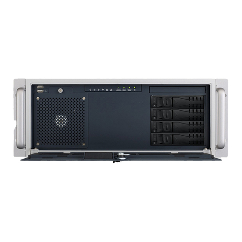
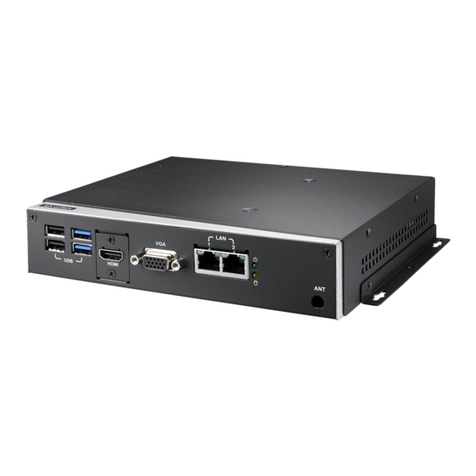
Advantech ITA-2000 User manual
Other Advantech Chassis manuals
Advantech
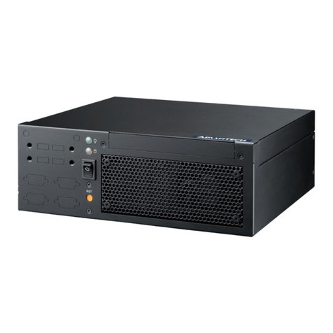
Advantech IPC-613 User manual
Advantech
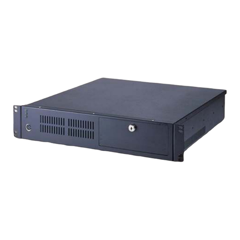
Advantech AIMB-B2000 User manual
Advantech
Advantech IPC-602 User manual
Advantech
Advantech EPD-B101 User manual

Advantech
Advantech AIMB-C300 User manual
Advantech
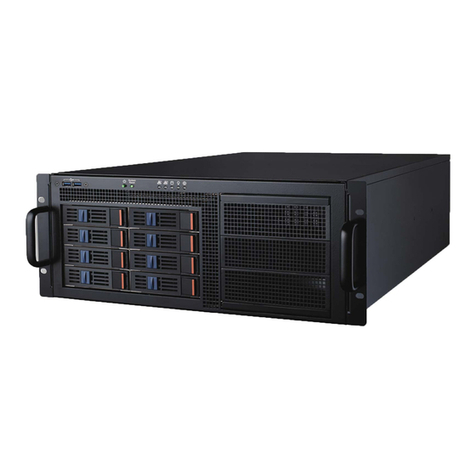
Advantech ACP-4D00 User manual
Advantech
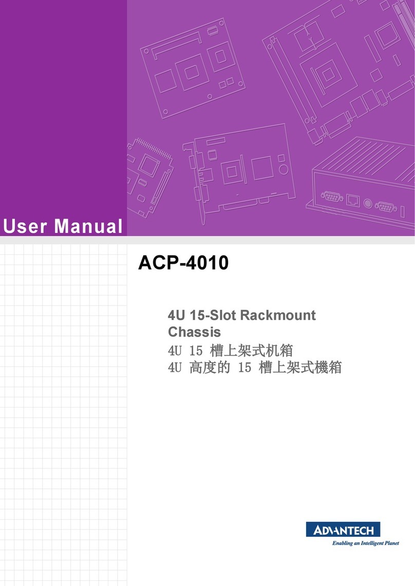
Advantech ACP-4010 User manual
Advantech
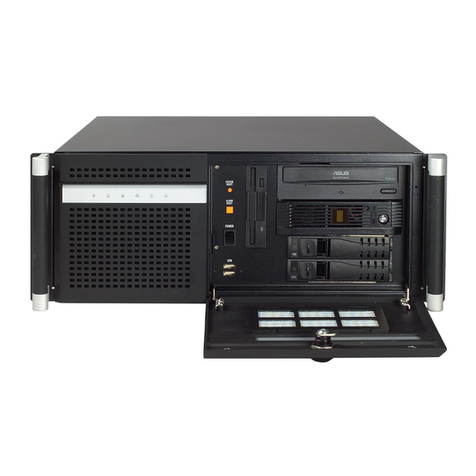
Advantech HPC-7483 User manual
Advantech
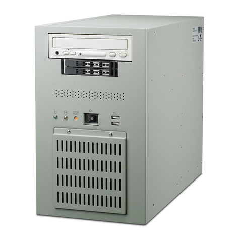
Advantech ACP-4320 User manual
Advantech
Advantech IPC-7132 User manual
Advantech
Advantech IPC-644 Series User manual
Advantech
Advantech HPC-8316 Series User manual
Advantech
Advantech HPC-7120 User manual

Advantech
Advantech IPC-6806 User manual
Advantech
Advantech HPC-7120S User manual
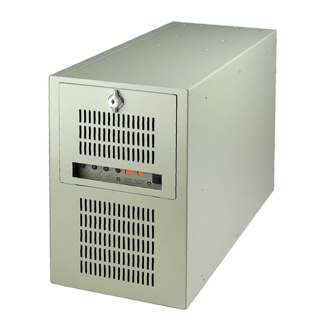
Advantech
Advantech IPC-7220 User manual
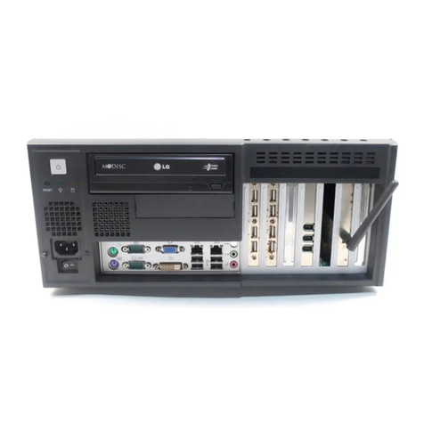
Advantech
Advantech IPC-7120 User manual

Advantech
Advantech ACP-4001 User manual
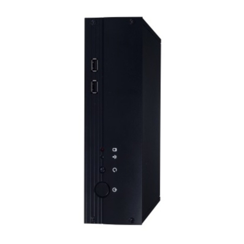
Advantech
Advantech AIMB-C200 User manual

Advantech
Advantech IPC-3012 User manual
Popular Chassis manuals by other brands
Phoenix Mecano
Phoenix Mecano HARTMANN ELECTRONIC PXCe4006 Series user manual

IMC Networks
IMC Networks iMcV/18 installation guide

Lenovo
Lenovo ThinkSystem SR665 V3 user guide

Wuntronic
Wuntronic PCI4DRQ user guide

EtherWAN
EtherWAN EMC400 quick start guide

Overland Storage
Overland Storage SnapSAN S1000 Replacement instructions

Cisco
Cisco Nexus 7010 Installing

Chenbro
Chenbro RM437 Series user manual
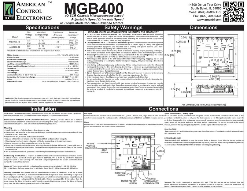
American Control Electronics
American Control Electronics MGB400 quick start guide
Cisco
Cisco USC 5030 installation guide
Enterasys
Enterasys K6 installation guide
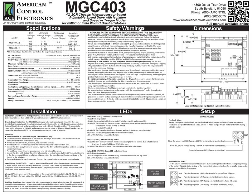
American Control Electronics
American Control Electronics MGC403 manual
