4
EFlow Kit Installation Guide
December 2017
GROW MORE WITH LESS®
FILTER ASSEMBLY
The 25mm Arkal Disc Filter is used to protect the system from
contamination of debris. It has a 130 micron ltration element
inside that requires cleaning periodically (see maintenance and
servicing). The Techlter is also required to provide the system
with trace elements of Triuralin. This chemical prevents roots
from blocking drippers. A Techlter is not required for
EFlow CNL XR and EFlow AS XR kits.
1. Assuming the outlet of the treatment plant is a 25mm male
thread, use a 25mm ratchet clamp to connect the 25mm
LDPE to the treatment plant with the 25mm Nut & Tail tting.
2. Using the ratchet clamp again, connect the 25mm Arkal Disc
Filter (black) to the 25mm LDPE with 25mm Nut & Tail ttings.
3. Now use the ratchet clamp to connect the 25mm Techlter
(black) to 25mm LDPE using 25mm Nut & Tail ttings.
IMPORTANT:
The arrow on the lter indicates the direction of ow
Filters should be installed facing down as shown in illustration
The Arkal Disc Filter is to be installed upstream of Techlter
If installing multiple zones, tees are to be installed after the
ltration system (Tees are provided in the ‘Add-on’ kit only).
The lter system is to be contained within the rectangular
valve box provided.
ZONE ASSEMBLY
1. Using the 25mm LDPE from the Filter Assembly, you need
to create a header assembly that runs perpendicular to the
dripperline. This will be buried below the surface in
Sub surface Dripperline Installations between
100mm and 200mm.
2. Attach the 25mm End Connectors to the end of the header
assembly using a 25mm ratchet clamp.
3. Using the punch tool, insert holes into the 25mm LPDE at lateral
spacings. With the ratchet clamp, attach the dripperline into
the Start Connectors and insert the tting into the hole on the
25mm LDPE. Ensure the tting and initial section of dripperline
remains perpendicular to the 25mm LDPE.
4. Using 25mm LDPE, install the Flush Manifold opposite the
header assembly.
5. Repeat the installation of Start Connectors between the
dripperline and LDPE for the Flush Manifold.
6. Insert the 25mm End Connectors at the highest end of the
Flush Manifold using a 25mm ratchet clamp.
FLUSH VALVE
The Flush Valve is used to clear any debris out of the system
during routine maintenance. The Flush Valve is located at the
lowest end of the Flush Manifold.
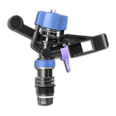
1. Screw the 25mm threaded elbow into the male Manual Flush
Valve. Be sure to apply thread tape (thread tape not provided).
2. Connect the threaded elbow to the 25mm LDPE Flush
Manifold using a 25mm ratchet clamp.
3. Install the Manual Flush Valve at 90° to the surface, ensuring
the lilac cap is level with the nish grade of the soil.
ASSEMBLY
