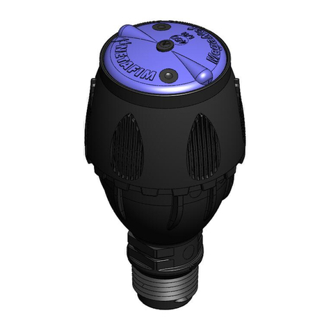
Netafim SPINNET User manual

V 001.01 - 2018
SPINNET
™
SD
VIBRONET
™
COOLNET PRO
™
MISTNET
™
SPINNET
™
MICRO-SPRINKLERS/EMITTERS
UPSIDE-DOWN
HANDBOOK

© COPYRIGHT 2017, NETAFIM™
NO PORTION OF THIS PUBLICATION MAY BE REPRODUCED, STORED IN AN AUTOMATED DATA FILE OR MADE PUBLIC
IN ANY FORM OR BY ANY MEANS, WHETHER ELECTRONIC, MECHANICAL, BY PHOTOCOPYING, RECORDING OR IN ANY
OTHER MANNER WITHOUT THE PRIOR WRITTEN CONSENT OF NETAFIM™.
THIS DOCUMENT IS PRESENTED WITH THE EXCLUSIVE AIM OF NOTIFYING SELECTED POTENTIAL CLIENTS REGARDING
THE NETAFIM™ DRIP IRRIGATION SYSTEM. RECEIPT OR THE POSSESSION OF THIS DOCUMENT SHALL NOT IMPLY
RIGHTS AND ITS CONTENTS SHALL BE VIEWED SOLELY AS A PROPOSAL. THIS DOCUMENT SHALL NOT IN ANY WAY
SERVE AS A GUARANTEE, NOR IS IT LEGALLY BINDING.
NETAFIM™ ENDEAVORS TO PROVIDE QUALITY, ACCURATE AND DETAILED INFORMATION. NEVERTHELESS, NETAFIM™
CANNOT ACCEPT ANY RESPONSIBILITY FOR RELIANCE ON THE INFORMATION PROVIDED HEREIN, AND THE USER
IS ADVISED TO OBTAIN THE PROFESSIONAL ADVICE OF NETAFIM™ AND/OR ITS AUTHORIZED REPRESENTATIVES
INDEPENDENTLY. THERE IS NO UNDERTAKING BY NETAFIM™ THAT THE INFORMATION PROVIDED HEREIN, OR ANY
PART THEREOF, IS ACCURATE, COMPLETE OR UP TO DATE.
MENTION OF THIRD PARTY PRODUCTS IS FOR SOLELY INFORMATIONAL PURPOSES AND CONSTITUTES NEITHER AN
ENDORSEMENT NOR A RECOMMENDATION. NETAFIM™ DOES NOT ASSUME ANY RESPONSIBILITY WITH RESPECT TO
THE USE OR THE PROVISIONS OF SUCH PRODUCTS.
NETAFIM™ SHALL NOT ACCEPT RESPONSIBILITY FOR ANY DAMAGE OR LOSS THAT MAY OCCUR FROM THE USE OF
ITS PRODUCTS OR THIS DOCUMENT.
NETAFIM™ RESERVES THE RIGHT TO MAKE CHANGES AND IMPROVEMENTS TO ITS PRODUCTS AND/OR THE
ASSOCIATED DOCUMENTATION WITHOUT PRIOR NOTICE.
FOREIGN LANGUAGES
In the event that you are reading this manual in a language other than English, you hereby
acknowledge and agree that the English language version shall prevail in case of inconsistency or
contradiction in interpretation or translation.

CONTENTS
Introduction
Use of symbols
Objectives of this document
Safety instructions
Micro-sprinkler/emitter selection
Introduction
Uses
Applications
Irrigation
Germination
Cooling
Rooting
Humidity increasing
Terms and concepts
Precipitation rate (Pr)
Water distribution uniformity
Max. length of distribution pipe
Head loss in the hanging micro-tube
Sprinkler water trajectory
Selecting a micro-sprinkler/emitter
Micro-sprinkler/emitter selection table
Micro-sprinklers/emitters assortment
Features and benefits
Drip-less and shadow-less emitters
Durability and low maintenance
Compliance with standard requirements
Anti-drain (AD) valves
SpinNet™
Description
Applications
Specifications
Filtration
Features and benefits
Performance
Water trajectory
Distribution uniformity
Head loss
SpinNet™ SD
Description
Applications
Specifications
Filtration
Features and benefits
Performance
Water trajectory
Distribution uniformity
Head loss
A particular case
4
5
5
6
6
6
6
7
7
8
8
8
9
9
15
15
16
17
17
18
18
18
18
18
19
19
19
19
20
20
20
21
21
22
23
23
23
23
24
24
25
25
25
26
27
VibroNet™
Description
Applications
Specifications
Filtration
Features and benefits
Performance
Water trajectory
Distribution uniformity
Head loss
CoolNet Pro™
Description
Applications
Three different configurations
Necessary terms
Mister vs. Fogger
Specifications
Filtration
Features and benefits
Performance
Water trajectory
Head loss
Applications
Cooling
Rooting
Humidity increasing
MistNet™
Description
Applications
Specifications
Filtration
Features and benefits
Performance
Water trajectory
Accessories and complementary products
Introduction
Anti-drain (AD) valve
Stabilizer (serves also as a tool)
PE flexible tube
Top connectors
Accessory connection
Appendix
Max. distribution pipe length
Warranty
29
29
29
29
29
29
30
30
30
30
31
31
31
31
31
32
32
32
32
33
33
33
34
34
35
35
36
36
36
37
37
37
37
37
38
38
39
40
40
41
42
46

4 UPSIDE-DOWN MICRO-EMITTERS HANDBOOK
INTRODUCTION
ELECTRICAL HAZARD
The following warning(s) contains instructions aimed at preventing bodily injury or direct damage
to the irrigation system components in the presence of electricity.
The symbols used in this document refer to the following:
WARNING
Instructions aimed at preventing bodily injury or direct damage to the crops and/or the irrigation
system.
CAUTION
Pertinent guidelines aimed at preventing unwanted system operation, installation or conditions.
Failure to follow said guidelines is liable to void the product's warranty.
ATTENTION
The subsequent text contains recommendations aimed at enhancing the efficiency of usage of
the instructions contained in the document.
NOTE
Specific points aimed at emphasizing a certain aspect of the operation or installation of the
system.
SAFETY FOOTWEAR
The subsequent instructions are aimed at preventing foot injury.
TIP
The following offers clarification, suggestions or useful information.
ACID HAZARD
The following warning(s) contains instructions aimed at preventing bodily injury or direct damage
to the crops and/or the irrigation system in the presence of acid.
PROTECTIVE EQUIPMENT
The subsequent instructions are aimed at preventing damage to health or bodily injury in
the presence of nutrients, acid or chemicals.
EXAMPLE
The following offers an example to clarify the operation of the settings, method of operation or
installation.
The values used in these examples are hypothetical and should not be applied to your own
situation.

UPSIDE-DOWN MICRO-EMITTERS HANDBOOK 5
Objectives of this document
This document's purpose is to present the basic concepts regarding upside down micro-sprinklers/emitter
systems for protected crops, to familiarize the reader with the system components and their functions,
and to provide an understanding of the parameters by which to select the optimal system for each
application.
It is intended for Netafim's personnel, its representatives and agents across the globe and for its clients,
their decision makers, managers and operational personnel.
The importance of thorough knowledge of the subjects discussed in this document for the selection and
effective operation of the micro-sprinkler/emitter system cannot be overemphasized.
ATTENTION
This document is not a user manual. For detailed instructions pertaining to the operation,
maintenance and troubleshooting of the components of the Netafim™ micro-sprinkler/emitter
system, refer to the user manuals and documentation of each component supplied with the system.
This document should be available to the farm's personnel at any time for consultation on subjects
concerning the correct application and current operation of the micro-sprinkler/emitter system.
In addition, Netafim's irrigation products department is at the client's service for any inquiry, advice or
additional information required after reading this document.
Safety instructions
All local safety regulations must be applied when installing, operating, maintaining and troubleshooting the
Netafim™ micro-sprinkler/emitter system and its components.
INTRODUCTION
WARNING
When handling nutrients, acids and chemicals, always use protective equipment,
gloves and goggles.
WARNING
In an agricultural environment - always wear protective footwear.
WARNING
Measures must be taken to prevent the infiltration of nutrients, acids and chemicals into the water
source.

6 UPSIDE-DOWN MICRO-EMITTERS HANDBOOK
MICRO-SPRINKLER/EMITTER SELECTION
Introduction
Netafim™ micro-sprinklers/emitters have been uniquely designed for upside-down installations, and
are the ideal solution for irrigation, cooling and humidity enhancing for protected crops in greenhouses,
tunnels, nurseries and net-houses. Our products enable unprecedented watering uniformity in both
standard full overlap installation and with our traditional "strip of micro-sprinklers/emitters".
The versatile Netafim™ line of micro-sprinklers/emitters covers a broad scope of applications; thereby
simplifying the design process. Whether you are designing a new application or retrofitting an existing
system, our micro-sprinklers/emitters offer highly reliable solutions for all your needs.
Uses
Protected crops in
•Greenhouses •Nurseries •Nethouses •Tunnels
Applications
Irrigation
Full coverage
There is no doubt that in most cases plant irrigation and fertilization is much more efficient and effective
when accomplished using drip systems. However, there are situations in which the farmer will choose to
use micro-sprinklers to perform this action, especially with protected crops. For instance, when there is a
very large quantity of potted plants per unit area, or when the crop is particularly dense and reaching each
plant with dripperlines would not be cost-effective. In such cases, the irrigation system must provide very
efficient and uniform watering.
For this purpose, Netafim™ proposes a network of SpinNet™ bridgeless micro-sprinklers (see page 19)
placed upside down (in the vast majority of protected crop applications) and by full overlap between the
wetted patterns produced by each emitter to create a uniform "rain" over the entire area.
Rectangular pattern Triangular pattern

UPSIDE-DOWN MICRO-EMITTERS HANDBOOK 7
MICRO-SPRINKLER/EMITTER SELECTION
Strip coverage
There are individual
cases, especially when
the crop is grown in
a tunnel or when the
grower wants to divide
one greenhouse span
into two separate
irrigation strips. In
such cases, only one
distribution pipe is
placed above the crop
and is not "assisted" by
micro-sprinklers on an
adjacent distribution
pipe.
For this purpose,
Netafim™ has developed
a dedicated solution:
the SpinNet™ SD (shoulder distribution) micro-sprinkler (see page 23) that allows farmers to achieve
excellent distribution uniformity with a very high wetting accuracy (i.e. a very high percentage of the water
actually falls within the strip under irrigation), thus increasing water use efficiency.
Germination
Germination is the process in which a seed is planted shallowly (only a few millimeters deep) and the
substrate (soil, substrate or a mix of both) is irrigated so that the seed germinates and becomes a young
plant.
For germination the irrigation must:
•Be very gentle, so that the water droplets will not move small clods of the soil/substrate and leave the
seed exposed, thereby possibly inhibiting proper germination.
•Provide perfect distribution uniformity. Germination is usually carried out on tables/trays divided into
individual cells (the water cannot pass through the boundary between substrate zones). Thus, although
very gentle, the water droplets must be able to provide perfect distribution uniformity.
For this purpose, Netafim™ proposes the VibroNet™ bridgeless micro emitter with vibrating action (see
page 29).
Cooling
Evaporative cooling (i.e. without contact between the water and the plants): a volume of air is cooled
by spraying very small droplets of water into the air. These droplets evaporate (thanks to the physical
attributes of condition equalization of objects when contacting each other). The droplets are at 100%
relative humidity (saturation) and the air inside the structure is at a lower relative humidity (the lower the
relative humidity of the air inside the structure, the more efficient the cooling action). The droplets turn
from liquid to gas (evaporation). Here another physical property enters in action: For every gram of water
evaporating, 560 calories are consumed from the air, as a result the air is cooled (The smaller the droplets,
the more efficient the evaporation resulting in a better cooling action).
For this purpose, Netafim™ proposes the CoolNet Pro™ super-fine mister (see page 31).

8 UPSIDE-DOWN MICRO-EMITTERS HANDBOOK
MICRO-SPRINKLER/EMITTER SELECTION
Terms and concepts
To select the appropriate micro-sprinkler system, one must be familiar with the following terms and concepts:
A.
Precipitation rate (Pr)
B.
Water distribution uniformity
• Christiansen Coefficient of Uniformity (%CU)
• Distribution uniformity (%DU)
• Scheduling Coefficient (SC)
C.
Distribution pipe maximum length
D.
Head loss in micro-tube and accessories
E.
Micro-sprinkler/emitter water trajectory
A. Precipitation rate (Pr)
The average amount of water applied to the irrigated area during a specified period, measured in this
manual in mm/h (millimeters per hour) units.
Calculating Pr
Pr (mm/h) = Micro-sprinkler/emitter flow rate (l/h) / [Spacing between micro-sprinklers/emitters in the
same distribution pipe (m) x Spacing between distribution pipes (m)]
EXAMPLE
Where:
Micro-sprinkler/emitter flow rate 70 l/h
Spacing between micro-sprinklers/emitters on the same distribution pipes 2.0 m
Spacing between distribution pipes 2.5 m
70 / (2 x 2.5) = 14.0
Pr = 14.0 mm/h
Rooting
This is necessary when the farmer wants to increase growth by cutting. For this purpose, a moist air
volume is required. The plant should be grown in a humid environment to facilitate growth of the new
roots. The emitters chosen for this purpose must be able to increase humidity in a uniform manner.
For this purpose Netafim™ proposes the CoolNet Pro™ super-fine mister (see page 31).
Humidity increasing
In some cases, the farmer is required to increase the humidity in the structure (regardless of the two
actions mentioned above). For example, when planting/sowing new plants in a relatively cold period, to
perform this operation correctly, it is necessary to heat the air inside the structure. This will dry the air.
Therefore, to ensure the beginning of a proper and effective growth, moisture must be added to the air.
For this purpose, Netafim™ proposes the CoolNet Pro™ super-fine mister (see page 31).

UPSIDE-DOWN MICRO-EMITTERS HANDBOOK 9
MICRO-SPRINKLER/EMITTER SELECTION
B. Water distribution uniformity
It is of vital importance that the irrigation water is distributed as evenly as possible throughout the irrigated
area. Properly designed micro-sprinklers/emitters enable greater distribution uniformity.
• Good distribution uniformity contributes to
higher yield and a higher quality crop.
• Poor distribution uniformity reduces yield and
crop quality and may damage the soil/substrate.
Netafim™ conducts rigorous tests to assess the distribution uniformity capacity of its micro-sprinklers/
emitters. The following is a brief summary of these testing procedures.
The water distribution uniformity survey: Setup and data collection
1.
A 4 X 4 micro-sprinklers/emitters grid (16 micro-sprinklers/emitters) is set up according to the planned
layout - spacing between micro-sprinklers/emitters
in the same distribution pipe and spacing between
distribution pipes.
ATTENTION
The survey must be conducted on a flat,
leveled and obstruction-free area.
Nine rectangular areas, each defined by 4 micro-
sprinklers/emitters at its four corners are produced.
2.
The center area is selected and a grid pattern
of rain gauges or catch cans is set up, with the
following distances between them each-
• 0.5 meter or less on both axes for
micro-sprinklers/emitters (flow rate ≥ 30 l/h)
• 0.25 meter or less on both axes for
micro-sprinklers/emitters (flow rate < 30 l/h)
ATTENTION
All the catch cans must be identical and placed in a leveled and stable position.
3.
The system is operated for 1 hour under normal operating conditions.
ATTENTION
The effect of wind on distribution uniformity is unpredictable.
For an accurate measurement, the system must not be operated under windy conditions.
4.
The level of the water collected in each gauge or can is measured and their results (in mm) noted as a
list, from the highest to the lowest.
Emitter
Catch cans
Distribution
pipe
10 UPSIDE-DOWN MICRO-EMITTERS HANDBOOK
MICRO-SPRINKLER/EMITTER SELECTION
There are 3 methods for calculating distribution uniformity:
• Christiansen Coefficient of Uniformity (%CU) - known to produce the most flattering results.
• Distribution uniformity (%DU) - known to be more rigorous than %CU.
• Scheduling Coefficient (SC) - known to be the most rigorous method of all.
Christiansen Coefficient of Uniformity (%CU)
The %CU is a measurement of uniformity, expressed as the average rate (%) of deviation from the overall
average application.
A perfectly uniform application is represented by a CU of 100%.
Lower uniformity applications are represented by lower percentages.
For micro-sprinkler/emitter irrigation of protected crops:
94% or higher Excellent uniformity
89% to 94% Very good uniformity
Lower than 89% Acceptable for certain low-value crops only
Limitation of the %CU method:
Due to the statistical nature calculation of the %CU method, it does not account for individual spots that
receive no water at all.
Calculating %CU
1.
Gather the water levels previously collected in each gauge or can (mm) [a].
2.
Sum all the numbers in column [a].
3.
The sum is divided by the number of gauges or cans placed. This provides the average net application of
the surveyed area [b].
4.
The average net application of the surveyed area [b] is subtracted from the amount of water collected
in each gauge or can (mm) [a]. Each result, whether lower or higher than the average net application, is
recorded as a positive number in column [c].
5.
All application deviations [c] are summed up.
6.
The sum is divided by the number of gauges/cans placed. This provides the average deviation from the
average net application of the surveyed area [d].
7.
The average deviation from the average net application [d] is divided by the average net application of
the surveyed area [b] and the result are subtracted from 1. This provides the CU of the surveyed area as
a percentage (%) [e].
NOTE
For simplicity, the examples below are based on 20 gauges/cans placed.

UPSIDE-DOWN MICRO-EMITTERS HANDBOOK 11
MICRO-SPRINKLER/EMITTER SELECTION
EXAMPLE
a b c d e
Net application
measurements
[mm]
Average net
application
[AVG]
Measurements [mm] -
average net application
= application deviations*
Average
deviation from
average net
application %CU
5.14
91.35 / 20 = 4.57
0.57
7.29 / 20 = 0.36 1 - (0.36 / 4.57) = 92.12
5.06 0.49
5.02 0.45
4.99 0.42
4.87 0.30
4.87 0.30
4.83 0.26
4.77 0.20
4.75 0.22
4.73 0.24
4.70 0.23
4.62 0.05
4.41 0.16
4.40 0.17
4.38 0.19
4.26 0.31
4.25 0.32
4.12 0.45
3.82 0.75
3.36 1.21
Sum:
91.35
Sum:
7. 2 9
*Application deviations are always recorded as positive numbers, whether the result is lower or higher
than the average net application [AVG].
Distribution uniformity (%DU)
The %DU is a measurement of uniformity, based on comparison of the driest 25% of the surveyed area
with the overall average net application, as a percentage.
%DU = (average of the lowest 25% / overall average) x 100
A perfectly uniform application is represented by a DU of 100%.
A less uniform application is represented by a lower percentage:
For micro-sprinkler/emitter irrigation of protected crops:
90% or higher Excellent uniformity
85% to 90% Very good uniformity
Lower than 85% Acceptable for certain low-value crops only

12 UPSIDE-DOWN MICRO-EMITTERS HANDBOOK
MICRO-SPRINKLER/EMITTER SELECTION
Advantage of the %DU method:
The measurement of %DU takes the driest results into account. Therefore it is better than %CU, as it
compares the area that receives the least water with the average application of the entire area.
Calculating %DU
1.
Gather the water levels previously collected in each gauge or can (mm) [a].
2.
Sum all the numbers in column [a].
3.
The sum is divided by the number of gauges or cans placed. This provides the average net application of
the entire surveyed area [b].
4.
The lowest 25% of the numbers in the column are summed up.
5.
The sum of the lowest 25% of the numbers in the column is divided by 25% of the number of gauges
or cans placed. This provides the average net application of the lowest 25% of the numbers
representing the surveyed area [c].
6.
The average net application of the lowest 25% of the numbers is divided by the average net application
of the entire surveyed area. This provides the DU of the surveyed area as a percentage (%) [d].
EXAMPLE
a b c d
Net application
measurements [mm]
Average net
application of the
entire area [AVG]
Average net application
of the lowest 25%
[AVG low] %DU
5.14
91.35 / 20 = 4.57 19.81 / (20 x 25%) = 3.96 (3.96 / 4.57) x 100 = 86.65
5.06
5.02
4.99
4.87
4.87
4.83
4.77
4.75
4.73
4.70
4.62
4.41
4.40
4.38
lowest 25%
4.26
4.25
4.12
3.82
3.36
Sum - entire area:
91.35
Sum - lowest 25%:
19.81

UPSIDE-DOWN MICRO-EMITTERS HANDBOOK 13
MICRO-SPRINKLER/EMITTER SELECTION
Scheduling Coefficient (SC)
The Scheduling Coefficient is a run-time multiplier. It represents the time needed to over-irrigate to achieve
the average application rate of the entire area in the driest part of the irrigated area.
SC = overall average net application / average net application in the driest parts of the irrigated area
Advantage of the SC method:
SC measurement takes into account the driest area (the part that receives the least water) while ensuring
that the entire area is irrigated with at least the minimum required quantity, according to the crop value.
NOTE
In protected crop applications, it is customary to consider 5% of the entire surveyed area as the
driest
area..
NOTE
The SC method is applicable solely for testing purposes, to validate the %CU and %DU methods and
less recommended for irrigation planning.
A perfectly uniform application is represented by an SC of 1.0.
A less uniform application is represented by a higher SC value:
For micro-sprinkler/emitter irrigation of protected crops:
Up to 1.0 Excellent uniformity
1.1 - 1.2 Very good uniformity
1.3 Good uniformity
Higher than 1.3 Acceptable for certain low-value crops only
Calculating SC
1.
Gather the water levels previously collected in each gauge or can (mm) [a].
2.
Sum all the numbers in column [a].
3.
The lowest 5% of the numbers in column [a] are summed up [only 1 number in this example].
4.
The sum of all the numbers in the column [a] is divided by the number of gauges or cans placed. This
provides the average net application of the entire surveyed area [b].
5.
The sum of the lowest 5% of the numbers in column [a] is divided by 5% of the number of gauges
or cans placed. This provides the average net application of the 5% lowest numbers in the surveyed
area [c].
6.
The sum of all the numbers in column [a] is divided by the sum of the lowest 5% of the numbers in
column [a]. This provides the SC value [d].

14 UPSIDE-DOWN MICRO-EMITTERS HANDBOOK
EXAMPLE
a b c d
Net application
measurements [mm]
Average net application
of the entire area [AVG]
Average net application of
the lowest 5% [AVG low] SC value
5.14
91.35 / 20 = 4.57 3.36 / (20 x 5%) = 3.36 (4.57 / 3.36) = 1.36
5.06
5.02
4.99
4.87
4.87
4.83
4.77
4.75
4.73
4.70
4.62
4.41
4.40
4.38
4.26
4.25
4.12
3.82
lowest 5%
3.36
Sum - entire area:
91.35
Sum - lowest 5%:
3.36
Conclusion:
The three instances above demonstrate that each method of calculating distribution
uniformity produces a different result.
Method Value Level of distribution uniformity
%CU
92.12 Very good
%DU
86.65 Very good
SC
1.36 Acceptable for some low value crops
It is common practice among micro-sprinkler/emitter manufacturers to advertise the results of the %CU
method only, which are known to be the most flattering. Netafim™, however, insisting on strict standards
and zealous R&D procedures, tests its micro-sprinklers/emitters with all 3 methods and provides its
customers with the results of the most rigorous analyses.
MICRO-SPRINKLER/EMITTER SELECTION

UPSIDE-DOWN MICRO-EMITTERS HANDBOOK 15
C. Maximum length of distribution pipe
When planning an irrigation system, it is of utmost importance not to exceed the maximum possible
length of distribution pipes to avoid a severe reduction of working pressure and in certain cases, irrigation
uniformity, i.e. efficiency, consequently resulting in a lower yield.
Various factors influence the maximum possible length of distribution pipes:
• Emitter flow rate
• Internal diameter of the distribution pipe (ID)
• Internal texture (roughness) of the distribution pipe (C)
• Distance between emitters on the distribution pipe
• Topographic slope of the distribution pipe
• Pressure at the inlet of the distribution pipe
The calculation of the maximum possible length of a distribution pipe is not a straightforward process. It
is dependent on various factors that interact in a non-linear manner. The result of the combination of the
different factors is not intuitively predictable (as demonstrated in the examples below).
The maximum possible length of a distribution pipe is reached when there is a 20% difference between
the highest pressure of the micro-sprinkler/emitter head and that, which receives the lowest pressure
along the distribution pipe (a 20% pressure difference corresponds to a 10% flow rate difference, which is
the accepted maximum for defining uniform irrigation).
The selection of the diameter of a distribution pipe must be based on the required flow rate. This factor
has the greatest influence on the maximum possible length of the distribution pipe.
EXAMPLE
Max. distribution pipe length at different slopes - 10% flow rate loss
Where:
Pipe
PE 20/4
ID 17.0 mm
Emitter
SpinNet™
Nominal flow rate 70 l/h
Head pressure 2.5 bar
Slope
Distance between emitters (m)
1.0 2.5 5.0
Max. distribution pipe length (m)
Uphill 1% 39 70 105
Flat terrain 040 73 115
Downhill -1% 41 75 120
D. Head loss in the hanging micro-tube and accessories
Since correct planning requires the consideration of the pressure needed at the micro-sprinkler/emitter
head, the head loss in the hanging micro-tube and accessories cannot be ignored.
The head loss in the hanging micro-tube and accessories is defined by the following factors:
•
Friction loss
The friction loss inside the hanging micro-tube and accessories depends on:
•The flow rate
•The internal diameter (ID) of the hanging micro-tube
•The length of the hanging micro-tube
•The internal texture (roughness) of the hanging micro-tube and accessories
•The internal design of each accessory (e.g. AD valve)
MICRO-SPRINKLER/EMITTER SELECTION

16 UPSIDE-DOWN MICRO-EMITTERS HANDBOOK
EXAMPLE
Friction loss in the hanging micro-tube and accessories
Where:
Micro-tube
length (cm)
Flow rate (l/h)
50 120 200
Head loss (bar)
Micro-
tube
AD
valve
Complete
unit
Micro-
tube
AD
valve
Complete
unit
Micro-
tube
AD
valve
Complete
unit
15 0.009 0.05 0.06 0.041 0.16 0.20 0 .10 0 0.38 0.48
60 0.035 0.05 0.08 0.16 3 0.16 0.32 0.400 0.38 0.78
120 0.070 0.05 0.12 0.325 0.16 0.49 0.799 0.38 1.18
Micro-tube
OD 6.5 mm
ID 4.0 mm
MICRO-SPRINKLER/EMITTER SELECTION
E. micro-sprinkler/emitter water trajectory
1.
Elevation of micro-sprinkler/emitter nozzle above surface
2.
Elevation of max. trajectory height above micro-sprinkler/emitter nozzle
3.
Distance of max. trajectory height from micro-sprinkler/emitter nozzle
4.
Max. wetted distance (dependant on nozzle elevation above surface).
Trajectory height above micro-sprinkler/emitter nozzle
The maximum trajectory height above the micro-sprinkler/emitter nozzle is relevant in the following cases:
• To prevent wetting the net or the ceiling.
• To prevent dripping from the distribution pipe.
• To prevent wetting the lighting fixtures.
2
3
1
4

UPSIDE-DOWN MICRO-EMITTERS HANDBOOK 17
Selecting a micro-sprinkler/emitter
CAUTION
An emitter can be properly selected only after attaining sufficient knowledge concerning all of the
factors of micro-sprinkler/emitter performance as explained above.
The micro-sprinkler/emitter is selected according to:
• The crops' needs
• The soil/substrate
• The grower's objectives
Definition of the following parameters is required:
• The distance between distribution pipes according to the span width
• Required water distribution uniformity according to crop value and expected profit
• Operating pressure
• The height of the micro-sprinkler/emitter above the surface
• The practicable trajectory height
It is not always possible to pinpoint the micro-sprinkler/emitter that perfectly satisfies all the above
prerequisites. In such a case, the most suitable micro-sprinkler/emitter should be selected by weighing the
above parameters according to their relative relevance to the crops' needs and the grower's objectives.
NOTE
Protected crops are extremely intensive, with very high input costs and an expected high return per
unit of area, and therefore a relatively low addition in a distribution pipe or two will not affect the
permission cost per square meter, but will assure significantly more uniform irrigation resulting in a
higher market valued quality crop.
Nevertheless, there are growers who insist on as few micro-sprinkler distribution pipes per span as
possible without taking into account the negative effects it has on the quality and market value of
the crop.
Micro-sprinkler/emitter selection table
Application Micro-sprinkler/emitter See page
Irrigation - full coverage SpinNet™ 19
Irrigation - strip coverage SpinNet™ SD 23
Irrigation above germination tables VibroNet™ 29
Evaporative cooling, rooting and humidity increasing CoolNet Pro™ 31
Under plant cooling MistNet™ 36
MICRO-SPRINKLER/EMITTER SELECTION

18 UPSIDE-DOWN MICRO-EMITTERS HANDBOOK
MICRO-SPRINKLERS/EMITTERS ASSORTMENT
Netafim™ micro sprinklers/emitters for protected crops -
Features and benefits
Drip-less and shadow-less micro-sprinklers/emitters
Netafim™ micro-sprinklers/emitters for protected crops are constructed
without a "bridge" to retain the spinner/deflector.
This benefit produces:
a. A drip-less operation.
Thus, plants located underneath the
micro-sprinklers/emitters are not damaged by water dripping from the
micro-sprinkler/emitter bridge. The micro-sprinklers/emitters hang below
the distribution pipe to protect the pipe from getting wet and dripping onto
the plants or cuttings below.
b. A shadow-less operation.
Thus, Netafim's micro-sprinklers/emitters
propose a higher distribution uniformity. There are no dry areas where
the water distribution is obstructed by a "bridge".
Durability and low maintenance
All Netafim™ micro-sprinklers/emitters are made from the highest quality,
durable and resistant plastics. The integration of acid resistant plastics enables
the use of acid treatment, standard agrochemicals and nutrients. All parts may
be easily assembled and disassembled without tools.
Compliance with international standard requirements
All Netafim™ micro-sprinklers/emitters are designed and tested according to the 8026 standard
requirements.
Reliable anti-drain (AD) valves
The incorporation of anti-drain (AD) valves assembled above the micro-sprinklers/emitters
ensures that all micro-sprinklers/emitters start and stop simultaneously, preventing
distribution pipe drainage and dripping onto the plants or cuttings below
(see details on page 38).
Emitter with bridge
Bridgeless emitter
Shadow Shadow
Bridge

UPSIDE-DOWN MICRO-EMITTERS HANDBOOK 19
MICRO-SPRINKLERS/EMITTERS ASSORTMENT
SpinNet™
Description
A bridgeless micro-sprinkler designed to operate exclusively in upside-down stands (the distribution pipe is
installed over the crop and the stand is attached hanging from the distribution pipe).
The SpinNet™ is proposed in 6 different flow rates (nozzles) and accommodates 3 different swivels
(rotors) to achieve optimal precipitation rate and ensure correct installation (at different distances) while
maintaining excellent distribution uniformity.
Nozzle-swivel (rotor) combinations
Swivel (rotor)
code color ›
LR
(long range)
Green
FLT
(flat distribution)
Light gray
SR
(short range)
Blue
Nozzle code
color
050 - Green N/A N/A
070 - Black
090 - Orange
120 -Red
160 - Brown
200 - Yellow
Nozzle
Swivel
Equipped with a press-fit (male/female) connection that ensures excellent grip even under high pressure
(as long as the installation is carried out according to the instructions. See page 40) and makes the
handling of the micro-sprinkler and its connection to accessories easy and user-friendly.
Applications
In greenhouses, nurseries and net-houses, the SpinNet™ is intended for use above any crop in wide
area irrigation. It is possible to plan full coverage/complete overlap while obtaining excellent distribution
uniformity.
Specifications
Models
050* 070 090 120 160 200
Nominal working pressure**
2.3 bar
Flow rates at nominal working pressure
50 l/h 67 l/h 91 l/h 120 l/h 161 l/h 199 l/h
Recommended working pressure range
2.0 - 3.0 bar
Swivel models
LR (long range) green
FLT (flat distribution) light gray
SR (short range) blue
Recommended filtration
130 micron / 120 mesh
*with SR swivel only
**Nominal working pressure is a manufacturer defined prerequisite of the International Standard 8026
and has no direct relationship with the recommended working pressure.

20 UPSIDE-DOWN MICRO-EMITTERS HANDBOOK
MICRO-SPRINKLERS/EMITTERS ASSORTMENT
Filtration
NOTE
The filtration method is to be selected based upon the type and concentration of dirt particles
existing in the water.
• Wherever sand exceeding 2 ppm exists in the water, a hydrocyclone sand separator is to be
installed upstream from the main filter.
• When sand/silt/clay solids exceed 100 ppm, preliminary treatment is to be applied according to
guidelines issued by Netafim's team of experts.
Features and benefits
• SpinNet™ micro-sprinklers are constructed without a "bridge" to retain the spinner. This benefit produces:
a. A drip-less operation
assuring that plants placed underneath the micro-sprinklers are not damaged by
water dripping.
b. A shadow-less operation
providing a higher distribution uniformity without dry areas where the water
distribution is obstructed by a "bridge".
• Interchangeable components. SpinNet™ micro-sprinklers can be disassembled manually should they
need cleaning - no tools are required.
• Acid resistant (AA) raw materials, thus allowing the application chemicals to pass through the system.
• The system can be cleaned by application of suitable acid treatments.
WARNING
When handling acid, always observe the product safety instructions and avoid acid coming in
contact with the crop, the soil/substrate and the environment.
• Excellent distribution uniformity on a full coverage irrigation system.
• It is strongly recommended to connect the SpinNet™ to the distribution pipe with a SSPE (super soft PE)
micro-tube, a specifically designed stabilizer and AD (anti-drain) valve (anti-drain) that will prevent
distribution pipe drainage.
Performance
Nozzle
Nozzle
size
(mm)
Constant
K*
Exponent
X*
050 0.90 10.5 0.5
070 1.07 14.0 0.5
090 1.22 18.9 0.5
120 1.44 25.0 0.5
160 1.76 33.6 0.5
200 1.86 41.4 0.5
Wetted diameter (meter)*
Swivel (rotor)
code color ›
LR FLT SR
Nozzle
050 N/A N/A 5.5
070 8.0 6.0 6.0
090 8.5 6.5 6.0
120 8.5 7.0 6.5
160 9.5 8.0 7.0
200 10.0 8.5 7.0
Wetted diameter
*Wetted diameter at 1.8 meter height above
surface and 2.5 bar working pressure. At least
0.5 mm/h
*The constant K and exponent X enable real flow
rate calculations at different working pressures
using the formula:
Q (l/h) = K*(P(meter)^X).
Flow rate calculation
This manual suits for next models
4
Table of contents
Other Netafim Irrigation System manuals

Netafim
Netafim NMC-JUNIOR PRO User manual

Netafim
Netafim GYRONET TURBO User manual

Netafim
Netafim nmc-pro User manual

Netafim
Netafim TECHLINE AS Guide

Netafim
Netafim SMART & GREEN 429854 User manual

Netafim
Netafim EFLOW CNL XR User manual

Netafim
Netafim SMART & GREEN 429861 User manual

Netafim
Netafim D-Net 6550 User manual

Netafim
Netafim nmc-pro User manual

Netafim
Netafim D-Net 8550 User manual