Costcare L440C User manual

Electric Stand Assist (Item: L440C)
Mobile Patient Lift
User Manual
DEALERS: This manual MUST be given to the user of the patient lift.
USER: Before using this patient lift, read this manual and save for future reference.
CAUTION: DO NOT attempt to adjust or operate patient lift without carefully reading all instruction in
this manual.

1
Table of Contents
1.0 GENERAL INFORMATION....................................................................................................................2
1.1 STANDARD SYMBOLS AND WARNING LABELS......................................................................................................2
1.2 INTENDED USE..............................................................................................................................................2
1.3 SAFETY PRECAUTIONS ....................................................................................................................................3
1.4 LIFE EXPECTANCY ..........................................................................................................................................7
2.0 TECHNICAL SPECIFICATION.................................................................................................................8
2.1 PATIENT LIFT ................................................................................................................................................8
3.0 EQUIPMENT ASSEMBLY......................................................................................................................9
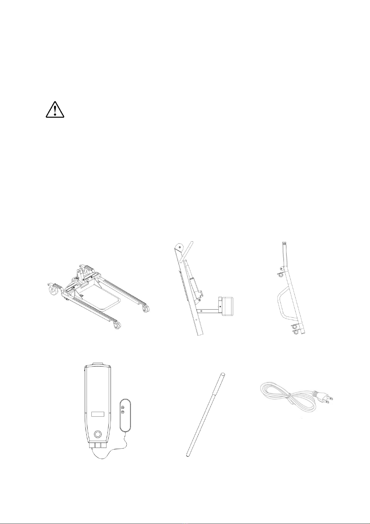
3.1 UNPACKING THE PATIENT LIFT .........................................................................................................................9
3.2 ASSEMBLING THE PATIENT LIFT.......................................................................................................................11
4.0EQUIPMENT OPERATION .................................................................................................................15
4.1 OPERATING THE PATIENT LIFT.........................................................................................................................15
4.2 CHARGING THE BATTERY...............................................................................................................................18
5.0 LIFTING THE PATIENT .......................................................................................................................20
5.1 PREPARING THE LIFT FOR USE.........................................................................................................................20
5.2 LIFTING/MOVING THE PATIENT......................................................................................................................21
5.3TRANSFERRING THE PATIENT..........................................................................................................................22
6.0 MAINTENANCE & CLEANING ............................................................................................................24
6.1 MAINTENANCE SCHEDULE.............................................................................................................................24
6.2 DETECTING WEAR AND DAMAGE ...................................................................................................................25
6.3 LUBRICATION..............................................................................................................................................25
6.4 CHECKING AND TIGHTENING MAST PIVOT BOLT ................................................................................................26
6.5 REPLACING THE ELECTRIC ACTUATOR ..............................................................................................................27
6.6 REPLACING THE KNEE PAD ............................................................................................................................28
6.7 REPLACING THE PATIENT STAND.....................................................................................................................28
6.8 MAINTAINING THE BASE ADJUSTMENT ............................................................................................................29
6.9 REPLACING THE CASTERS/FORKS ....................................................................................................................29
6.10 CLEANING .............................................................................................................................................31
7.0 TROUBLESHOOTING GUIDE..............................................................................................................32
1.0 LIMITED WARRANTY ........................................................................................................................33
APPENDIX –SERVICE RECORD........................................................................................................................34

2
1.0 GENERAL INFORMATION
1.1 Standard Symbols and Warning Labels
Warnings
Signal words with symbols are used in this manual to highlight hazards or unsafe practices
which could result in personal injury or property damage. See the information below for
definitions of the signal words and symbols.
DANGER
Danger indicates an imminently hazardous situation which, if not avoided, will result
in death or serious injury.
WARNING
Warning indicates a potentially hazardous situation which, if not avoided, could
result in death or serious injury.
CAUTION
Caution indicates a potentially hazardous situation which, if not avoided, may result
in property damage or minor injury or both.
IMPORTANT
Indicates a hazardous situation that could result in damage to equipment or property
if it is not avoided.
Gives useful tips, recommendations and information for ease of use.
1.2 Intended Use
The Electric Stand Assist Lift are intended for use in within an institutional healthcare
environment, i.e. hospitals, nursing homes, rehabilitation care, assisted living.
The patient lift is NOT a transport device. It is intended to transfer an individual from
one resting surface to another (such as a bed to a wheelchair).
DO NOT attempt any transfer without approval of the patient’s physician, nurse or
medical assistant.

3
The lifters are intended for users who fully understood the content of this manual and
is not intended for use by children.
1.3 Safety Precautions
1.3.1 Assembling the Lift
WARNING
DO NOT overtighten the mounting hardware as this will damage the mounting
brackets.
1.3.2 Operating the Lift
WARNING
DO NOT exceed maximum weight limitation of the patient lift. The weight limitation
for the lift is 400 lbs.
ALWAYS ensure there is an audible click when mounting battery on the battery
charger to confirm proper mounting. Otherwise, injury or damage may occur.
ALWAYS keep hands and fingers away from moving parts to avoid injury.
Although two assistants are recommended for all lifting preparation and transferring
procedures, our equipment will permit proper operation by one assistant. The use
of one assistant is based on the evaluation of the health care professional for each
individual case.
1.3.3 Using the Slings
WARNING
Use a sling advised by the individual’s doctor, nurse or medical assistant for the
comfort and safety of the individual being lifted.
DO NOT insert any kind of plastic back incontinence pad or seating cushion between
patient and sling material that may cause the patient to slide out of the sling during
transfer.

4
After each wash (in accordance with instructions on the sling), inspect sling(s) for
wear, tears, and loose stitching. Bleached, torn, cut, frayed, or broken slings are
unsafe and could result in injury, and should be DISCARDED immediately.
DO NOT alter slings.
Be sure to check the sling attachments each time the sling is removed and replaced,
to ensure that it is properly attached before the patient is removed from a stationary
object (bed, chair or commode).
If the patient is in a wheelchair, secure the wheel locks in place to prevent chair
movements that could lead to potential falls.
1.3.4 Lifting the Patient
WARNING
When using the lift, the legs MUST be opened to the maximum position and locked
before lifting the patient.
The rear casters of the patient lift MUST be kept unlocked when lifting an individual.
Locking the casters during lifting procedures could cause the lift to tip and endanger
the patient and assistants. The unlocked casters during lifting procedures will allow
the patient lift to stabilize itself when the patient is initially lifted from a chair, bed
or any stationary object.
Specific slings are made for the Electric Stand Assist Patient Lift. For the safety of the
patient, DO NOT intermix slings and patient lifts of different manufacturers.
Warranty will be voided.
When the patient is elevated a few inches off a stationary surface and before moving
the patient, check again to make sure that all hardware or straps are properly
connected. If any attachment is NOT properly in place, lower the patient back onto
the bed and rectify the issue.
Adjustments for safety and comfort should be made prior to moving the patient.
Patient's arms should be kept inside of the straps.
When lifting a patient, make sure the patients feet stand firmly on the foot stand and
knees tightly against the knee pad.

5
During transfer, with patient in a sling attached to the lift, DO NOT roll caster base
over uneven surfaces that could cause the patient lift to tip over. Use steering handle
on the mast at all times to maneuver the patient lift.
1.3.5 Transferring the Patient
WARNING
When the patient is elevated a few inches off a stationary surface and before moving
the patient, check again to make sure that all hardware or straps are properly
connected. If any attachment is NOT properly in place, lower the patient back onto
the bed and rectify the issue.
Wheelchair wheels MUST be locked before lowering the patient into the wheelchair
for transport.
Make sure the wheelchair weight capacity can withstand the patient's weight prior
to loading the patient.
Be sure to check the sling attachments each time the sling is removed and replaced,
to ensure that it is properly attached before the patient is removed from the bed or
chair.
Mast pivot must be tight to ensure safe use of the patient lift. Bolt must be checked
at least every six months in conjunction with periodic maintenance.
1.3.6 Performing Maintenance
WARNING
ONLY qualified personnel should carry out the lift maintenance.
DO NOT attempt to open the pre-sealed actuator or obtain local service, for it will
VOID the warranty and might result in damage. Consult your dealer or manufacturer
for further information.
Inspect the casters and axle bolts every six months to check for tightness and wear.
Regular maintenance of patient lifts and accessories is necessary to ensure proper
operation. DO NOT overtighten mounting hardware. This will damage mounting
brackets.

6
1.3.7 Electrical and Grounding
WARNING
Thoroughly read through the battery/battery charger information prior to installing,
servicing or operating your patient lift.
GROUNDING
DO NOT, under any circumstances, cut or remove the grounding prong from any plug.
Some devices are equipped with three-prong (grounding) plugs for protection
against possible shock hazards. Where a two-prong wall receptacle is encountered,
it is the personal responsibility and obligation of the customer to contact a qualified
electrician and have the two-prong receptacle replaced with a properly grounded
three-prong wall receptacle in accordance with the National Electrical Code. If you
must use an extension cord, use ONLY a three-wire extension cord having the same
or higher electrical rating as the device being connected.
1.3.8 Disposal
WARNING
This product has been supplied from an environmentally aware manufacturer.
Device contains lead acid batteries. DO NOT dispose of batteries in normal household
waste. They MUST be taken to a proper disposal site. Contact your local waste
management company for information.
This product may contain substances that could be harmful to the environment if
disposed of in places (landfills) that are not appropriate according to legislation.
Please be environmentally responsible and recycle this product through your
recycling facility at its end of life.
1.3.9 Radio Frequency Interference
WARNING
Most electronic equipment is influenced by Radio Frequency Interference (RFI).
CAUTION should be exercised with regard to the use of portable communication
equipment in the area around such equipment. If RFI causes erratic behavior, PUSH
the Red Power Switch OFF IMMEDIATELY. DO NOT turn the Power Switch ON while
transmission is in progress.

7
1.4 Life Expectancy
The lift expectancy of the lift is eight years, presuming that the product is used daily
and in accordance with safety instructions and maintenance instructions stated in this
manual.

8
2.0 TECHNICAL SPECIFICATION
2.1 Patient Lift
L440C Electric Stand Assist Lift
Height at Sling Hook-up - MAX
70”
Height at Sling Hook-up - MIN
33.6”
Base Width OPEN
40”
BASE Width Closed
25”
Base Height (Clearance)
4.5”
Base Length
48”
Caster Size (Front/Rear)
3”/ 5”
Weight Capacity
400 lbs
Weight IN Carton
137 lbs
Weight OUT of Carton
122 lbs
Battery
24V DC
Charger Input
100-240V AC
Accessories
Battery Wall Charger
Battery Status
LCD Display
Approx. Lifts per Charge (Varies depending
upon load and stroke)
100-200 Cycles per charge
Warranty Electronics
1 Year

9
3.0 EQUIPMENT ASSEMBLY
3.1 Unpacking the Patient Lift
WARNING
To avoid injury, DO NOT attempt to remove the lift from the carton without
assistance.
I. Unpack the components from the shipping carton.
II. Upon unpacking your patient lift, the package should contain all of the following
components.
III. Examine exterior of the patient lift for nicks, dents, scratches or damages. Inspect
all components.
Main component provided in the package:
Lift Caster Base x 1
Mast assembly x 1
Boom x 1
Control Box & Hand Pendant x 1
Shifter Handle x 1
Charging Power Cord x 1

10
Tools also provided in the package:
Allen Wrench x 2 (size M8 & M10)
Wrench
YOU SHOULD PREPARE THE FOLLOWING TOOLS FOR THE LIFT ASSEMBLY:
Crosshead Screwdriver x 1
Not all items provided in the carton are shown in the above. Pinch guards, bolts,
washers and nuts are fastened to their intended locations and therefore omitted from
the illustration.
IMPORTANT
Store the repackaged patent lift in a dry area. Do not place other objects on top of
the repackaged patient lift.
Unless the lift is to be used immediately, retain boxes, containers, and packing
materials for use in storing until use of patient lift is required.

11
3.2 Assembling the patient lift
WARNING
Use only parts supplied by the manufacturer for assembly. The base legs, the mast,
boom, and actuator assembly are manufactured to specifications that assure correct
alignment of all parts for safe operation.
3.2.1 Assembling the mast to the base
I. Step on the locking levers to lock the two rear casters at the base.
II. Remove the shoulder bolt, washer and nut fastened to the base of the mast
mounting bracket.
III. Position the mast in an upright position and place the mast over the U-shape cut-
out of the base.
IV. Insert shoulder bolt with washers through the base and mast, secure with nut.

12
WARNING
For storage or transport, the mast may be disconnected from the base. Each time
the mast is removed and returned to the base, the mast MUST be properly secured
to the base assembly.
3.2.2 Assembling the boom to the mast
The bottom of the actuator assembly will be preassembled to the mast mounting
bracket.
I. Remove the shoulder bolt, bushing and nut fastened to the boom mounting
bracket.
II. Lift-up on the boom align its mounting holes with the mounting bracket on the
mast.
III. Insert the shoulder bolt and washer, secure the boom to mast with nut.
3.2.3 Assembling the electric actuator to the boom
The bottom of the actuator assembly will be preassembled to the mast mounting
bracket.
I. Remove the shoulder bolt, washer and nut fastened to the boom mounting
bracket.
II. Lift-up on the boom and place it on your left shoulder.
III. Align the holes of the boom assembly mounting bracket with those of the actuator
and insert the bolt. Secure with nut.

13
Be sure that the bolt is completely through the holes of the boom assembly mounting
bracket and the actuator assembly. The boom assembly will pivot easily if the
mounting hardware is aligned properly when the boom assembly is secured.
3.2.4 Assembling the control box to the mast
I. Slide the control box onto the mounting bracket on the boom. Make sure the
control box is held by the slide track.
II. With one hand holding down the control box, plug the actuator cord to the
bottom of the control box. The hand pendant should already be connected.

14
3.2.5 Installing the shifter handle
I. Line-up the shifter handle opening with the threaded connector at the base.
II. Turn the shifter handle clockwise and securely tighten into the base.
III. Secure the shifting handle in place with a cross head screw.

15
4.0 EQUIPMENT OPERATION
4.1 Operating the patient lift
4.1.1 Closing/Opening the Legs of the lift base
Stand at the rear of the lifter and grasp the shifter handle. Swivel the shifter handle to
open and close the legs of the base.
The shifter handle MUST lock into its mounting slot to lock the legs in the full
close/open position.
WARNING
The shifter handle MUST be positioned completely into its mounting slot. DO NOT
use the patient lift until shifter handle is properly seated and the legs of the patient
lift are locked in place. Otherwise, injury and/or damage may occur.
4.1.2 Adjusting the leg support height
I. To adjust the height of the patient leg support, pull on the plunger at the rear of
the knee pad to release the lock.
II. Adjust the knee pad by moving it up or down. There are five adjustment holes.
III. Release the plunger at the preferred height. Make sure there is an audible click
and the cushion is locked in position.

16
4.1.3 Raising/lowering the electric lift
WARNING
The rear casters of the patient lift should not be locked when lifting an individual.
Locked casters could cause the lift to tip and endanger the patient and assistants. It
is recommended that the rear casters be left unlocked during lifting procedures to
allow the patient lift to stabilize itself when the patient is initially lifted from a chair,
bed or any stationary object.
To raise the patient lift, press ○
1the boom UP button ( up arrow)
to raise the boom and the patient.
To lower the patient lift, press ○
2the boom DOWN button ( down
arrow) to lower the boom and the patient.
○
3alarms the user when the load exceeds the lift capacity, and the
indicator light will come on.
○
4displays battery status with light indicators.

17
Where the hand pendant is absent or at fault,
the control box can be used to lower and raise
the patient lift.
The buttons for raising and lowering the lift is
located on the front of the control box above
the emergency stop button.
4.1.4 Activating the emergency stop
Press the RED/ORANGE emergency button on the control box to stop the boom
assembly and patient from raising or lowering. Rotate the RED/ORANGE emergency
stop button clockwise to disengage the emergency stop.

18
4.2 Charging the Battery
It is recommended that the battery should be recharged daily to prolong battery life.
The battery status can be viewed on the LCD display at the front of the control box.
4.2.1 Charging the battery with power cord
I. Use the charging cord provided in the carton, plug the pins into an appropriate
grounded electrical socket.
II. Insert the other end of the power cord into the corresponding socket on the side
of the control box.
III. The indication light on the hand pendant will illuminate to indicate the battery is
being charged.
The lift will not be operable whilst the battery is being charged. Keep the lift casters
locked and lift stationary.
Left: Standard Electrical Lifter Control Box

19
4.2.2 Charging the battery with standalone charger
The standalone charger is an accessory and should be ordered separately.
I. Flip open the hinged lid at the top of the control box to expose the internal battery.
II. Lift the battery up and out away from the control box.
III. Place the battery in the standalone battery charger. At this point, the battery
charger should be unplugged and the switch on the charger switched to “O” (off)
position. The LCD screen on the charger will display the battery status.
IV. Plug the power cord for the standalone charger into a grounded mains socket.
Switch on the battery charger. The indicator light on the battery charger will turn
red.
V. Once fully charged the indicator light will turn green. Lift up on the strap handle
on the top of the battery.
VI. Lift the battery up and out away from the battery charger
VII. Reinstall the battery onto the control box. Make sure there is an audible click
when closing the lid.
IMPORTANT
The emergency stop on the control box must be activated, button PRESSED IN, when
mounting the battery. If not, potential power surge could damage the control box.
Table of contents
Other Costcare Medical Equipment manuals
Popular Medical Equipment manuals by other brands

idi
idi Aspect ISO-Drive Operator's manual

ConMed
ConMed Sabre 2400 Operators & service manual

bort medical
bort medical 104 400 quick guide

Vapotherm
Vapotherm precision flow Operating instructions manual

Kodak
Kodak X-Omatic MULTILOADER 300 Modification Instructions

Boston Scientific
Boston Scientific Precision Montage SC-1200 Directions for use