Netgate Netgate-2100 User manual

Security Gateway Manual
Netgate-2100
© Copyright 2023 Rubicon Communications LLC
Jul 18, 2023

OUT OF THE BOX
1 Getting Started 2
2 Initial Configuration 4
3 pfSense Plus Software Overview 11
4 Input and Output Ports 15
5 Safety and Legal 18
6 Netgate 2100 Wall Mount 26
7 Connecting to the USB Console Port 29
8 Reinstalling pfSense Plus Software 38
9 Optional M.2 SATA Installation 43
10 Configuring the Switch Ports 47
11 Configuring an OPT interface as an additional WAN 53
12 Configuring an OPT interface as an additional LAN 60
13 Factory Reset Procedure 68
14 Switch Overview 69
15 Additional Resources 71
16 Warranty and Support 72
i

Security Gateway Manual Netgate-2100
This Quick Start Guide covers the first time connection procedures for the Netgate® 2100 Firewall Appliance. It will
provide the information needed to keep the appliance up and running.
Tip: Before getting started, a good practice is to download the PDF version of the Product Manual and the PDF
version of the pfSense Documentation in case Internet access is not available during setup.
© Copyright 2023 Rubicon Communications LLC 1

CHAPTER
ONE
GETTING STARTED
The basic firewall configuration begins with connecting the Netgate® appliance to the Internet. The Netgate appliance
should be unplugged at this time.
Connect one end of an Ethernet cable to the WAN port (shown in the Input and Output Ports section) of the Netgate
appliance. The other end of the same cable should be inserted into a LAN port on the ISP CPE device, such as a cable
or fiber modem. If the CPE device provided by the ISP has multiple LAN ports, any LAN port should work in most
circumstances.
Next, connect one end of a second Ethernet cable to the LAN port (shown in the Input and Output Ports section) of
the Netgate appliance. Connect the other end to the computer.
2

Security Gateway Manual Netgate-2100
1.1 What next?
To connect to the GUI and configure the firewall in a browser, continue on to Initial Configuration.
To connect to the console and make adjustments before connecting to the GUI, see Connecting to the USB Console
Port.
Warning: The default IP Address on the LAN subnet on the Netgate firewall is 192.168.1.1/24. The same
subnet cannot be used on both WAN and LAN, so if the default IP address on the ISP-supplied modem is also
192.168.1.1/24,disconnect the WAN interface until the LAN interface on the firewall has been renumbered
to a different subnet (like 192.168.2.1/24) to avoid an IP Address conflict.
To change an interface IP address, choose option 2 from the Console Menu and walk through the steps to change
it, or from the GUI, go through the Setup Wizard (opens at first boot, also found at System > Setup Wizard) and
change the IP address on Step 5. Complete the Wizard and save the changes.
© Copyright 2023 Rubicon Communications LLC 3

CHAPTER
TWO
INITIAL CONFIGURATION
Plug the power cable into the power port (shown in the Input and Output Ports section) to turn on the Netgate®
Firewall. Allow 4 or 5 minutes to boot up completely.
Warning: If the CPE on WAN (e.g. Fiber or Cable Modem) has a default IP Address of 192.168.1.1,
disconnect the Ethernet cable from the WAN port on the Netgate 2100 Security Gateway before proceeding.
Change the default LAN IP Address of the device during a later step in the configuration to avoid having conflicting
subnets on the WAN and LAN.
2.1 Connecting to the Web Interface (GUI)
1. From the computer, log into the web interface
Open a web browser (Google Chrome in this example) and enter 192.168.1.1 in the address bar. Press
Enter.
Fig. 1: Enter the default LAN IP address in the browser
2. A warning message may appear. If this message or similar message is encountered, it is safe to proceed. Click
the Advanced Button and then click Proceed to 192.168.1.1 (unsafe) to continue.
3. At the Sign In page, enter the default pfSense®Plus username and password and click Next.
• Default Username: admin
• Default Password: pfsense
4

Security Gateway Manual Netgate-2100
Fig. 2: Example certificate warning message
© Copyright 2023 Rubicon Communications LLC 5

Security Gateway Manual Netgate-2100
2.2 The Setup Wizard
This section steps through each page of the Setup Wizard to perform the initial configuration of the firewall. The
wizard collects information one page at a time but it does not make any changes to the firewall until the wizard is
completed.
Tip: The wizard can be safely stopped at any time for those who wish to perform the configuration manually or
restore an existing backup (Backup and Restore).
To stop the wizard, navigate away from the wizard pages by clicking the logo in the upper left of the page or by
choosing an entry from one of the menus.
Note: Ignore the warning at the top of each wizard page about resetting the admin account password. One of the
steps in the Setup Wizard is to change the default password, but the new password is not applied until the end of the
wizard.
1. Click Next to start the Setup Wizard.
Fig. 3: Setup Wizard starting page
2. Click Next after reading the information on Netgate Global Support.
3. Use the following items as a guide to configure the options on the General Information page:
Hostname Any desired hostname name can be entered to identify the firewall. For the purposes of
this guide, the default hostname pfsense is used.
Domain The domain name under which the firewall operates. The default home.arpa is used for
the purposes of this tutorial.
© Copyright 2023 Rubicon Communications LLC 6

Security Gateway Manual Netgate-2100
DNS Servers For purposes of this setup guide, use the Google public DNS servers (8.8.8.8 and
8.8.4.4).
Note: The firewall defaults to acting as a resolver and clients will not utilize these forwarding
DNS servers. However, these servers give the firewall itself a way to ensure it has working DNS
if resolving the default way does not work properly.
Fig. 4: General Information page in the Setup Wizard
Type in the DNS Server information and Click Next.
4. Use the following information for the Time Server Information page:
Time Server Hostname Use the default time server address. The default hostname is suitable for
both IPv4 and IPv6 NTP clients.
Timezone Select a geographically named time zone for the location of the firewall.
For this guide, the Timezone will be set to America/Chicago for US Central time.
Change the Timezone and click Next.
5. Use the following information for the Configure WAN Interface page:
The WAN interface is the external (public) IP address the firewall will use to communicate with the Internet.
DHCP is the default and is the most common type of WAN interface for home fiber and cable modems.
Default settings for the other items on this page should be acceptable for normal home users.
Default settings should be acceptable. Click Next.
© Copyright 2023 Rubicon Communications LLC 7

Security Gateway Manual Netgate-2100
Fig. 5: Time Server Information page in the Setup Wizard
Fig. 6: Configure WAN Interface page in the Setup Wizard
© Copyright 2023 Rubicon Communications LLC 8

Security Gateway Manual Netgate-2100
6. Configuring LAN IP Address & Subnet Mask. The default LAN IP address of 192.168.1.1 and subnet mask
of 24 is usually sufficient.
Tip: If the CPE on WAN (e.g. Fiber or Cable Modem) has a default IP Address of 192.168.1.1, the Ethernet
cable should be disconnected from the WAN port on the Netgate 2100 Security Gateway before starting.
Change the default LAN IP Address of the device during this step in the configuration to avoid having conflicting
subnets on the WAN and LAN.
7. Change the Admin Password. Enter the same new password in both fields.
8. Click Reload to save the configuration.
9. After a few seconds, a message will indicate the Setup Wizard has completed. To proceed to the pfSense®Plus
dashboard, click Finish.
Note: This step of the wizard also contains several useful links to Netgate resources and methods of obtaining
assistance with the product. Be sure to read through the items on this page before finishing the wizard.
2.3 Finishing Up
After completing or exiting the wizard, during the first time loading the Dashboard the firewall will display a notifi-
cation modal dialog with the Copyright and Trademark Notices.
Read and click Accept to continue to the dashboard.
If the Ethernet cable was unplugged at the beginning of this configuration, reconnect it to the WAN port now.
This completes the basic configuration for the Netgate appliance.
© Copyright 2023 Rubicon Communications LLC 9

Security Gateway Manual Netgate-2100
Fig. 7: Copyright and Trademark Notices
© Copyright 2023 Rubicon Communications LLC 10

CHAPTER
THREE
PFSENSE PLUS SOFTWARE OVERVIEW
This page provides an overview of the pfSense®Plus dashboard and navigation. It also provides information on how to
perform frequent tasks such as backing up the pfSense®Plus software and connecting to the Netgate firewall console.
3.1 The Dashboard
pfSense®Plus software is highly configurable, all of which can be done through the dashboard. This orientation will
help to navigate and further configure the firewall.
Fig. 1: The pfSense®Plus Dashboard
Section 1 Important system information such as the model, Serial Number, and Netgate Device ID for this Netgate
firewall.
Section 2 Identifies what version of pfSense®Plus software is installed, and if an update is available.
Section 3 Describes Netgate Service and Support.
11

Security Gateway Manual Netgate-2100
Section 4 Shows the various menu headings. Each menu heading has drop-down options for a wide range of config-
uration choices.
3.2 Re-running the Setup Wizard
To re-run the Setup Wizard, navigate to System > Setup Wizard.
Fig. 2: Re-run the Setup Wizard
3.3 Backup and Restore
It is important to backup the firewall configuration prior to updating or making any configuration changes. From the
menu at the top of the page, browse to Diagnostics > Backup/Restore.
Click Download configuration as XML and save a copy of the firewall configuration to the computer con-
nected to the Netgate firewall.
This backup (or any backup) can be restored from the same screen by choosing the backed up file under Restore
Configuration.
Note: Auto Config Backup is a built-in service located at Services > Auto Config Backup. This service will save
up to 100 encrypted backup files automatically, any time a change to the configuration has been made. Visit the Auto
Config Backup page for more information.
© Copyright 2023 Rubicon Communications LLC 12

Security Gateway Manual Netgate-2100
Fig. 3: Backup & Restore
Fig. 4: Click Download configuration as XML
© Copyright 2023 Rubicon Communications LLC 13

Security Gateway Manual Netgate-2100
3.4 Connecting to the Console
There are times when accessing the console is required. Perhaps GUI console access has been locked out, or the
password has been lost or forgotten.
See also:
Connecting to the USB Console Port. Cable is required.
Tip: To learn more about getting the most out of a Netgate appliance, sign up for a pfSense Plus Software Training
course or browse the extensive Resource Library.
3.5 Updates
When a new version of pfSense Plus software is available, the device will indicate the availability of the new version
on the System Information dashboard widget. Users can peform a manual check as well by visiting System > Update.
Users can initiate an upgrade from the System > Update page as needed.
For more information, see the Upgrade Guide.
Warning: Some older installations of pfSense Plus software on Netgate 2100 and Netgate 2100 MAX devices
contain an EFI partition which does not have sufficient space to accommodate the new EFI loader for version 23.01
and later. This primarily affects UFS-based systems initially installed with version 21.02-p1 or before.
For details, see Troubleshooting Upgrades on Netgate 1100 and Netgate 2100 Devices.
© Copyright 2023 Rubicon Communications LLC 14

CHAPTER
FOUR
INPUT AND OUTPUT PORTS
4.1 Rear Side
Fig. 1: Rear view of the Netgate 2100 Firewall Appliance
The items in this image are described by entries in Routed Ethernet,Switched Ethernet, and Other Ports.
4.1.1 Routed Ethernet
The WAN Combo-Port is shared between an RJ-45 port and an SFP port. Only one port can be used.
Interface Name Port Name
WAN mvneta0
LED Pattern Description
Left LED only green Flashes with 1Gb traffic, solid with link.
Both LEDs green Both flash with 100Mb traffic, solid with link.
Right LED only green Flashes with 10Mb traffic, solid with link.
15

Security Gateway Manual Netgate-2100
4.1.2 Switched Ethernet
Interface Name Port Name
LAN1 mvneta1
LAN2 mvneta1
LAN3 mvneta1
LAN4 mvneta1
The four LAN Ethernet ports are switched ports. By default all of these ports act as a single switch uplinked to the
LAN interface on the firewall.
Note: For more details on how the switch operates, see Switch Overview.
For instructions on how to configure the switch see Configuring the Switch Ports.
LED Pattern Description
Both LEDs green Left Flashes with 1Gb traffic, solid with link.
Left LED only green Left flashes with 100Mb traffic, solid with link.
Right LED only green Left Flashes with 10Mb traffic, solid with link.
Warning: The LAN ports do not support the Spanning Tree Protocol (STP). Two or more ports connected to
another Layer 2 switch, or connected to 2 or more different interconnected switches, could create a flooding loop
between the switches. This can cause the router to stop functioning until the loop is resolved.
4.1.3 Other Ports
• Power (12 VDC with threaded locking connector)
• Recessed Reset Button (performs a reset to factory default)
• USB 2.0 Port
• Micro SIM
•Mini-USB Serial Console
• 3x SMA-sized antenna holes (covered by rubber caps)
Note: The reset button is only used to reset the system back to factory defaults. It does not respond when pushed
while the system is running. See Factory Reset Procedure.
© Copyright 2023 Rubicon Communications LLC 16

Security Gateway Manual Netgate-2100
USB Ports
USB ports on the device can be used for a variety of purposes.
The primary use for the USB ports is to install or reinstall the operating system on the device. Beyond that, there
are numerous USB devices which can expand the base functionality of the hardware, including some supported by
add-on packages. For example, UPS/Battery Backups, Cellular modems, GPS units, and storage devices. Though the
operating system also supports wired and wireless network devices, these are not ideal and should be avoided.
4.2 Front Side
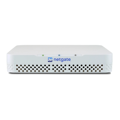
Fig. 2: Front view of the Netgate 2100 Firewall Appliance
4.2.1 LED Patterns
Description LED Pattern
Boot in Process Circle, then square, then diamond all rapidly flash blue
Boot Completed/Ready Diamond slowly flashes blue
Upgrade Available Square slowly flashes orange
Upgrade in Progress Square slowly flashes orange
Factory Reset All rapidly flash red
© Copyright 2023 Rubicon Communications LLC 17

CHAPTER
FIVE
SAFETY AND LEGAL
5.1 Safety Notices
1. Read, follow, and keep these instructions.
2. Heed all warnings.
3. Only use attachments/accessories specified by the manufacturer.
Warning: Do not use this product in location that can be submerged by water.
Warning: Do not use this product during an electrical storm to avoid electrical shock.
5.2 Electrical Safety Information
1. Compliance is required with respect to voltage, frequency, and current requirements indicated on the manu-
facturer’s label. Connection to a different power source than those specified may result in improper operation,
damage to the equipment or pose a fire hazard if the limitations are not followed.
2. There are no operator serviceable parts inside this equipment. Service should be provided only by a qualified
service technician.
3. This equipment is provided with a detachable power cord which has an integral safety ground wire intended for
connection to a grounded safety outlet.
a) Do not substitute the power cord with one that is not the provided approved type. If a 3 prong plug is
provided, never use an adapter plug to connect to a 2-wire outlet as this will defeat the continuity of the
grounding wire.
b) The equipment requires the use of the ground wire as a part of the safety certification, modification or
misuse can provide a shock hazard that can result in serious injury or death.
c) Contact a qualified electrician or the manufacturer if there are questions about the installation prior to
connecting the equipment.
d) Protective grounding/earthing is provided by Listed AC adapter. Building installation shall provide appro-
priate short-circuit backup protection.
e) Protective bonding must be installed in accordance with local national wiring rules and regulations.
18
Table of contents
Other Netgate Gateway manuals
Netgate
Netgate SG-3100 User manual

Netgate
Netgate SG-3100 User manual
Netgate
Netgate SG-4860 User manual
Netgate
Netgate Netgate-6100 User manual
Netgate
Netgate XG-7100-1U User manual
Netgate
Netgate FXS Series User manual

Netgate
Netgate SG-3100 User manual
Netgate
Netgate SG-1100 User manual
Netgate
Netgate SG-5100 User manual
Netgate
Netgate SG-2100 User manual
