Netio PowerBOX 3PF User manual

PowerBOX 3Px
PowerBOX 4Kx
MANUAL
FIRMWARE 3.1.0
and later
7.4.2021

2
Table of Contents
Introduction.............................................................................................................4
1Safety notices ....................................................................................................4
2General characteristics .........................................................................................5
3Specifications.....................................................................................................7
3.1 Features .............................................................................................8
3.2 Drawings ........................................................................................... 10
3.3 Device description ............................................................................... 12
3.4 LED and button functions....................................................................... 13
3.5 Minimum system requirements (for configuration) ........................................ 13
3.6 Package contents ................................................................................ 14
3.7 Optional accessories............................................................................. 14
4Configuration and control .................................................................................... 15
4.1 Connectiong PowerBOX ......................................................................... 15
4.2 Detecting and configuring the IP address.................................................... 15
4.3 Login to device web ............................................................................. 17
4.4 NETIO Mobile2 for Android ..................................................................... 18
4.5 Restoring factory defaults...................................................................... 19
4.6 Controlling the output manually .............................................................. 19
5Web interface .................................................................................................. 20
5.1 Outputs ............................................................................................ 20
5.1.1 Outputs - Energy measurements –PowerBOX 4Kx only ....................... 22
5.1.2 Outputs - General ................................................................... 24
5.1.3 Outputs - Schedule .................................................................. 26
5.2 Open API: M2M Protocols ....................................................................... 27
5.2.1 M2M API Protocol –XML over HTTP............................................... 28
5.2.2 M2M API Protocol –JSON over HTTP ............................................. 33
5.2.3 M2M API Protocol –URL API (http get)........................................... 37
5.2.4 M2M API Protocol –Telnet ......................................................... 40
5.2.5 M2M API Protocol –Modbus/TCP .................................................. 45
5.2.6 M2M API Protocol –MQTT-flex..................................................... 49
5.2.7 M2M API Protocol –Netio Push .................................................... 53
5.2.8 M2M API Protocol –SNMP........................................................... 55
5.3 Cloud ............................................................................................... 59
5.4 Users ............................................................................................... 62
5.5 Schedules.......................................................................................... 64
5.6 Settings ............................................................................................ 66
5.6.1 Network Configuration ............................................................. 66
5.6.2 Date / Time .......................................................................... 68
5.6.3 Firmware.............................................................................. 69
5.6.4 System................................................................................. 71
5.7 Log.................................................................................................. 73
6DECLARATION OF CONFORMITY.............................................................................. 75
7Products overview ............................................................................................. 77

3

4
Introduction
Thank you for purchasing this product of NETIO products a.s. Before using your product, please read
this User Manual (MAN) and the included Quick Installation Guide (QIG) to avoid problems with incorrect
installation or use.
Caution:
The product works with mains voltage. Mishandling may damage it or result in injury or death.
1Safety notices
1. The manufacturer is not liable for any damage caused by incorrect use of the device or by
operating it in an unsuitable environment.
2. The device is not rated for outdoor use.
3. Do not expose the device to strong vibrations.
4. Unauthorized modifications may damage the device or cause a fire.
5. Protect the device from liquids and excessive temperatures.
6. Make sure the device does not fall.
7. Only electrical appliances approved for use with the electrical network may be connected to the
device.
8. Do not connect multiple devices in series.
9. The cable plug must be easily accessible.
10. The device is completely switched off only when unplugged.
11. If the device malfunctions, disconnect it from the electrical outlet and contact your vendor.
12. Do not cover the device.
13. Do not use the device if it appears to be mechanically damaged.
14. Make sure that the input and output cables are rated for the respective current.

5
2General characteristics
PowerBOX 3Px
Switched Power Outputs: 3
Output Switching: ZVS (Zero Voltage Switching)
Metered channels: 0
PowerBOX 4Kx
Switched Power Outputs: 4
Output Switching: ZCS (Zero Current Switching)
Metered channels: 4
Electricity consumption metering: [V, Hz, A, W, Wh, TPF, °]
Measurement accuracy <1%
Common
LAN interface 10/100 Mbps (RJ-45)
Built-in web server for device configuration and control
Password-protected login into device configuration
IOC (Independent Output Control)
PowerUp state - (ON / OFF / LAST)
Overvoltage protection
Operating temperature range: -20°C to +65°C
Supported protocols: DNS, NTP, DHCP, HTTP, uPNP
Supported M2M protocols: Modbus/TCP, Telnet, SNMP, MQTT-flex, Http Push, XML, JSON, URL
API
Overview of PowerBOX 3Px and PowerBOX 4Kx variants according to the electrical socket type
e.g. PowerBOX 4KF use Euro input plug (CEE 7/7) and Type F (Schuko) output sockets
“x”
Variant
Output socket
Input plug
Voltage
Max.
current
Max.
load
F
DE
Type F
E/F (CEE 7/7)
230V ~
16A
3600W
E
FR
Type E
E/F (CEE 7/7)
230V ~
16A
3600W
G
UK
Type G
Type G
230V ~
13A
3000W

6
Figure 1 –PowerBOX variants
3PF
3PE
3PG
4KE
4KF
4KG

7
3Specifications
Power
100-240 V; 50/60 Hz; 16 A - PowerBOX 3PE, PowerBOX 4KE
100-240 V; 50/60 Hz; 16 A - PowerBOX 3PF, PowerBOX 4KF
100-240 V; 50/60 Hz; 13 A - PowerBOX 3PG, PowerBOX 4KG
Switched outputs
16 A in total / 16 A each output - PowerBOX 3PE, PowerBOX 4KE
16 A in total / 16 A each output - PowerBOX 3PF, PowerBOX 4KF
13 A in total / 13 A each output - PowerBOX 3PG, PowerBOX 4KG
Maximum line breaker
capacity
C16A –PowerBOX 3PE, PowerBOX 4KE
C16A –PowerBOX 3PF, PowerBOX 4KF
C13A –PowerBOX 3PG, PowerBOX 4KG
Fuse
Integrated, non-resettable
Surge protection
Type 3 (CAT III)
Power Output relays
Micro-disconnection (µ) (resistive load), SPST-NO
1E5 switching cycles, max. 1.5 kV pulse voltage
Switch heat and fire resistance class 1
Electrical load
PowerBOX 3Px: ZVS (Zero Voltage Switching)
- most load types, such as switching power supplies compatible
PowerBOX 4Kx: ZCS (Zero Current Switching)
- Resistance load compatible
- Capacitive load compatible
- Inductive load compatible
Network interfaces
1x Ethernet RJ-45 10/100 Mbit/s
Attention! Device connected over LAN must be connected in
network with same earth potential (PE).
Internal consumption
Max 2W
Environment
IP30, protection rating = class 1
Operating temperature -20°C to 65°C / 10A
-20°C to 50°C / 16A
Device rated for pollution degree 2.
Designed for continuous operation in altitudes up to 2000 m.
Does not require additional cooling

8
3.1 Features
ZCS (Zero Current Switching) –PowerBOX 4Kx
ZCS (Zero Current Switching) function ensures that the relay contact is closed
at the moment of zero voltage and opened at the moment when zero current
flows through it.
Closing and opening at these exact moments has a number of advantages:
The negative effects of inrush current on the lifetime of the relay in the
NETIO device are significantly reduced.
Reduced probability of a circuit breaker tripping in the circuit branch
where the appliance with a high inrush current is connected.
Significantly improved lifetime of switching supplies in appliances that are connected to the
socket (especially in case of frequent switching on and off).
Significantly reduced electromagnetic interference caused by repeated switching on and off.
Zero current switching (ZCS) significantly improves the lifetime of the NETIO device and the
connected end devices. This function is particularly important in case of frequent switching.
ZVS (Zero Voltage Switching) –PowerBOX 3Px
ZVS (Zero Voltage Switching) means switching the 110/230VAC output when
the immediate voltage is zero.
ZVS is a good solution for switching on/off devices such as switching power
supplies.
ZVS is not suitable for controlling inductive loads (transformers or motors), as
it increases the probability of relay damage when such types of loads are
frequently switched on/off.
NETIO products without energy metering support ZVS (Zero Voltage Switching) when switching
110/230V relay outputs.
ZVS is sufficient relay switching technology for most load types, such as switching power supplies in
IT solutions.
IOC (Independent Output Control)
Independent Output Control function of the NETIO device uses an independent
system that ensures a stable operation of the output even if the main system
is being restarted, updated, or is booting.
Thanks to IOC, the controlled output can power devices that, for technical
reasons, must be powered without interruption (such as servers). The output
control is completely independent from the WiFi or LAN communication
subsystem.
ZCS
Zero Current
IOC
Independent IO
ZVS
Zero Voltage

9
PowerUp State
The PowerUp State parameter (sometimes also called Cold start) defines the
behavior of the 110/230V power output during the first milliseconds to seconds
after powering up the device, before the LAN/WiFi communication with a
master system is established.
For some applications, it is important to set the correct state of a power
output immediately after power is turned on (or restored). With servers in
particular it is important to avoid undesired momentary switching.
Possible settings for NETIO device
- On
- Off
- LAST state restores the last state before the power was disconnected
Electrical measurements –only PowerBOX 4Kx
PowerBOX 4Kx measures relevant electrical parameters.
Parameter
Range
Units
Resolution
Accuracy
Voltage
90,0 –250,0
V
0,1
<1%
Frequency
45,0 –65,0
Hz
0,1
<1%
Current
0,005 –16,000
A
0,001
<1%
TPF
(True Power Factor)
0,00 –1,00
-
0,01
<1%
Phase
0 –360
°
0,01°
<1%
Output power
0 –3600
W
1
<1%
Energy
0 - 4294967296
Wh
1
<1%
Reverse Energy
0 - 4294967296
Wh
1
<1%
PowerUp
state

10
3.2 Drawings
PowerBOX 3Px
Figure 2 –PoweBOX 3Px front and side view [mm]
Figure 3 –PoweBOX 3Px - overall dimensions in mm with MK1 kit installed (MK1 sold separately)

11
DIN rail mounting option details
Figure 4 –PoweBOX cut view

12
3.3 Device description
PowerBOX 3Px
1. 1x RJ45 LAN connector
2. RJ45 LEDs –device states (yellow and green)
3. Multifunction “SETUP” button
Figure 5 –PowerBOX 3Px description
PowerBOX 4Kx
1. 1x RJ45 LAN connector
2. RJ45 LEDs –device states (yellow and green)
3. Multifunction “SETUP” button
4. M2M activity LED (red)
Figure 6 –PowerBOX 4Kx description
3
2
1
3
2
1
4

13
3.4 LED and button functions
LED indicators
RJ45 –green
Network Link (lit) + Activity (flashes)
RJ45 –yellow
1x flash when the device starts
3x flash when the internal system restarts
Flashing (2 sec lit, 1 sec dark) when the Eth cable is disconnected
and the device is running (connected to power).
M2M (red) –only PowerBOX 4Kx
Blink when some M2M communication is in progress.
Blink when NETIO Cloud communication is in progress.
Device Web administration / Mobile app is not indicated.
SETUP button
Switching all outputs
Output test:
Press the SETUP button 3x rapidly.
–If any of output is On (1) -> Off (0).
–If all outputs are Off (0), All outputs -> On (1).
Restoring factory defaults
Disconnect the device from the power. Press and hold the button.
Connect the device to the power grid (button is pushed) and wait at
least 10 seconds until the yellow LED on the RJ45 jack flashes 3 times,
release the button.
The device reverts to factory settings.
3.5 Minimum system requirements (for configuration)
A device with an Internet browser (Firefox, Chrome, Safari, Microsoft Internet Explorer, Opera, Mozilla
etc.) that has JavaScript and cookies enabled.
14
3.6 Package contents
- NETIO PowerBOX 3Px or PowerBOX 4Kx device with fixed power cable.
- Printed Quick Installation Guide (QIG)
Figure 7 –PowerBOX QIG
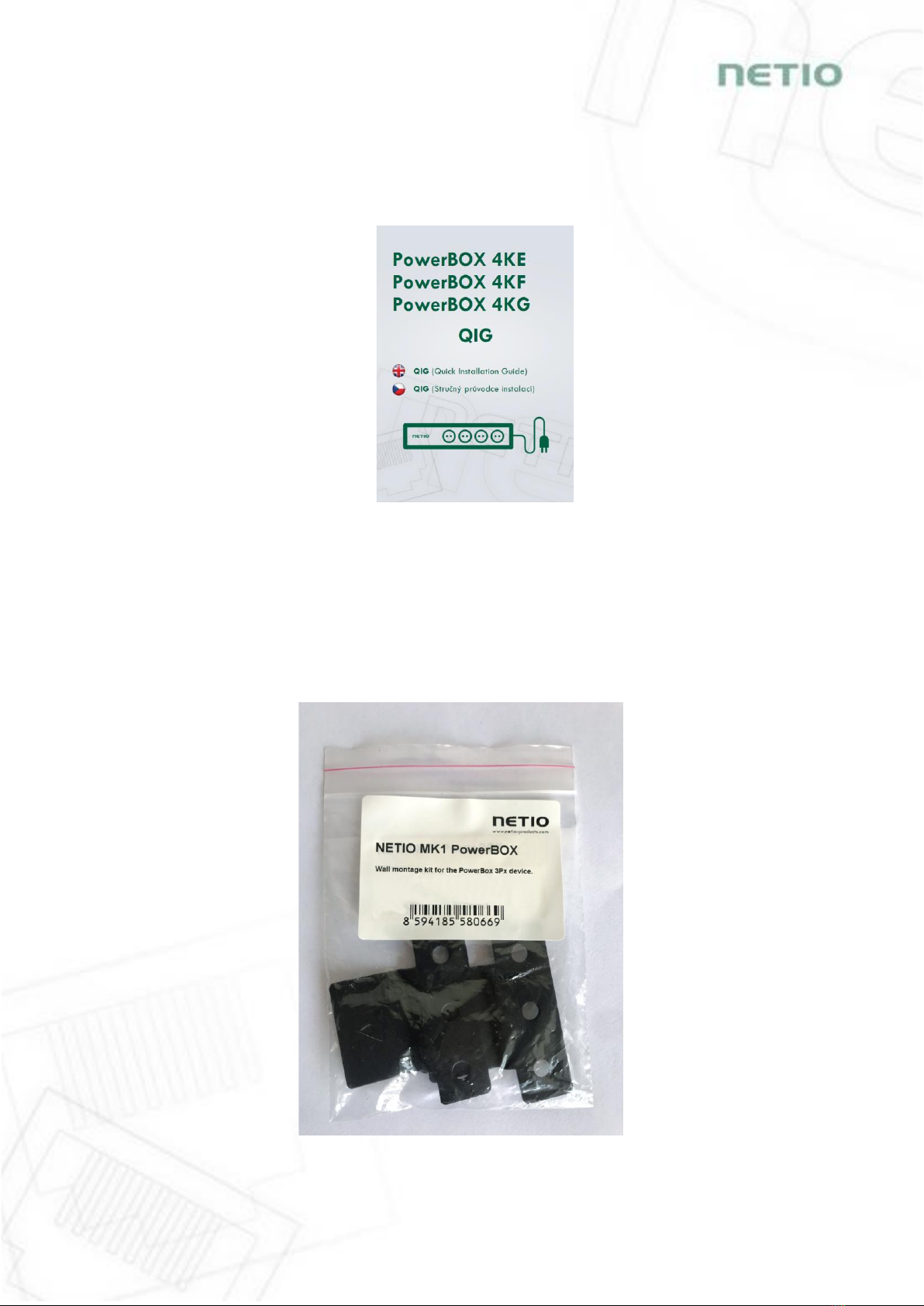
3.7 Optional accessories
- NETIO MK1 PowerBOX –wall mounting kit for PowerBOX 3Px and PowerBOX 4Kx devices
Figure 8 –NETIO MK1 PowerBOX

15
4Configuration and control
4.1 Connectiong PowerBOX
NETIO PowerBOX use the Ethernet connection (RJ45) to network.
Connect your NETIO device to a LAN with a network cable (RJ45).
Plug the input cable plug into the electrical socket.
Wait about 30 seconds until the device starts and address is provided from a DHCP server.
Note: It is mandatory to have DHCP server in the network for the first connection to LAN and Setup.
The IP can be switched to Static afterwards.
4.2 Detecting and configuring the IP address
If you have followed the instructions in the previous chapter, you know the NETIO device’s IP
address, whether it was assigned by a DHCP server or configured manually. If you forgot the IP
address, or if you have received a pre-configured device, you will need to find out its IP address.
Use Windows based NETIO Discover utility, available for download at http://www.netio-
products.com/en/software/netio-discover.
Figure 9 –NETIO Discover web interface
To successfully discover the IP address, the controlling system must be in the same LAN as the
NETIO device.
If the discovered IP address belongs to a different address range than that of your network, we
recommend resetting the device to factory defaults (see chapter Restoring factory defaults) and
then configuring it according to chapter Configuration and control.

16
Figure 10 –Discovering and configuring network parameters using NETIO Discover (MS Windows)
To change the IP address, click the value in the MAC address column, uncheck Enable DHCP and
specify the IP address, Subnet mask and Default gateway. After applying the settings, NETIO device
will be accessible at the specified address.
Enter the IP address into a web browser or the NETIO Mobile app and log in to the device.
Note: If you can’t use MS Windows app, use NETIO Mobile2 App for Android.
See details in the chapter NETIO Mobile2 for Android
Note: For MAC or Linux users check http://wiki.netio-products.com

17
4.3 Login to device web
Figure 11 –PowerBOX login dialog
To log in, use admin / admin
(default login username / password)

18
4.4 NETIO Mobile2 for Android
NETIO Mobile2 application is for control NETIO devices
produced after 2016.
Features:
Switch On / Off / Restart each power socket on local
network.
Show power consumption on each power output (if
supported).
Searching NETIO devices in local network
Install NFC enabled NETIO devices
https://play.google.com/store/apps/details?id=cz.netio.netio

19
4.5 Restoring factory defaults
This operation deletes all user settings and restores the configuration to the factory defaults. It is
useful when the device is in an unknown state or does not behave as described in this manual.
Procedure:
1. Turn off (unplug) the PowerBOX from power grid.
2. Press and hold the button.
3. Connect the device plug to the power grid (button is still pushed) and wait at least 10 until the
yellow LED on the RJ45 jack flashes 3 times, release the button.
4. The device reverts to the factory settings.
Forgotten password
The reset to factory defaults is also used when the password has been forgotten. After
restoring the factory defaults, the username and password to access the PowerBOX will
be “admin” / “admin”.
4.6 Controlling the output manually
The outputs can be switched on/off (toggled) by pressing the button quickly 3 times in a row.
1. Press the “DEFAULT” button three times fast to toggle the outputs.
Note: If at least one output is ON the “toggle” by button change all outputs to OFF. If all outputs
are OFF the “toggle” change all to ON.

20
5Web interface
5.1 Outputs
In the left menu, click Outputs. A screen showing the output appears. The output can be controlled
directly with two buttons:
Figure 12 –Controlling the output
1) The ON/OFF button controls the output directly. When the output is on, the button is
green; when the output is off, the button is grey . When switching the output off, a
confirmation dialog appears:
This manual suits for next models
5
Table of contents
Other Netio Accessories manuals

Popular Accessories manuals by other brands

Bin Master
Bin Master SmartBob AO operating instructions

Master cool
Master cool MMBT12 Installation and operation manual

Chef's Choice
Chef's Choice Chef's Choice AngleSelect DC 1520 instructions

globalwater
globalwater WL400 manual

HIK VISION
HIK VISION DS-KB6403-WIP user manual

Silvercrest
Silvercrest 60494 Operation and safety notes


BLACK DECKER
BLACK DECKER BDC24L manual

1 BY ONE
1 BY ONE SimpleTaste instruction manual

IB Connect
IB Connect Box user manual

SON
SON System 9 CVX user manual

Heath Zenith
Heath Zenith Wireless Push Button Accessory 598-1151-02 owner's manual

Silvercrest
Silvercrest STK 36 B2 Assembly, operating and safety instructions