NETmc Marine videoPWR User manual

USER GUIDE FOR
NETmc MARINE
videoPWR
Camera / lamp controller units
Rev 3.2 July 2010
NETmcMarine videoPWR Rev3.2 1 of 15

Contents
1. INTRODUCTION.................................................................................................................3
2. VIDEOPWRPELI.................................................................................................................4
2.1 Hardware Description and Connections....................................................................4
2.2 Electrical:......................................................................................................................4
3. VIDEOPWR DUAL - RACKMOUNT VERSION..................................................................5
3.2 Hardware Description and Connections....................................................................5
Front of the unit .......................................................................................................................5
Back of the unit........................................................................................................................5
3.3 Electrical:......................................................................................................................6
3.4 Video enhancement.....................................................................................................7
4. HOW TO CONTACT NETMC MARINE SUPPORT ............................................................7
APPENDIX 1 ...........................................................................................................................9
Technical Specifications.........................................................................................................9
APPENDIX 2 .........................................................................................................................10
Wiring Pin-Out of Souriau Umbilical Connector.................................................................10
Spare parts:............................................................................................................................10
APPENDIX 3 .........................................................................................................................11
Wiring Pin-Out of Amphenol Umbilical Connector.............................................................11
APPENDIX 4 .........................................................................................................................12
Screw terminal wiring (where applicable)............................................................................12
APPENDIX 5 .........................................................................................................................13
LYYN Visiblity Enhancement Technology...........................................................................13
NETmc Marine Ltd
New Deer, Turriff
Aberdeenshire
AB53 6TL
U.K.
TEL. +44 1771 644001
FAX. +44 1771 644005
NETmcMarine videoPWR Rev3.2 2 of 15

1. Introduction
NETmc Marine videoPWR camera / lamp controller units have been supplied in 2 separate models:
- a videoPWRpeli which is fitted into a Pelicase for ease of transportation, and is used to control
one diver camera and lamp system
- a single/dual channel 1U rackmount videoPWR which provides control of up to 2 separate diver
camera and lamp systems. The dual channel version has 100% replication for each diver
system, with separate mains inputs, switches and umbilical output sockets.
For an additional cost video enhancement technology can be fitted into the unit.
VideoPWR camera/lamp controllers are designed to work with our customer’s own camera/lamps as
requested:
- Where a Souriau umibilical connector is fitted (see Appendix 2), the videoPWR unit has been
designed specifically for use with Novasub underwater cameras parts CAMSS2.3TP and
CAMSS2.4C, and Novasub LED lights part LUX6LSS1.4-12.
- If a different or no connector is fitted please contact us to find out which camera/lamps systems the
videoPWR is designed to work with.
NETmcMarine videoPWR Rev3.2 3 of 15
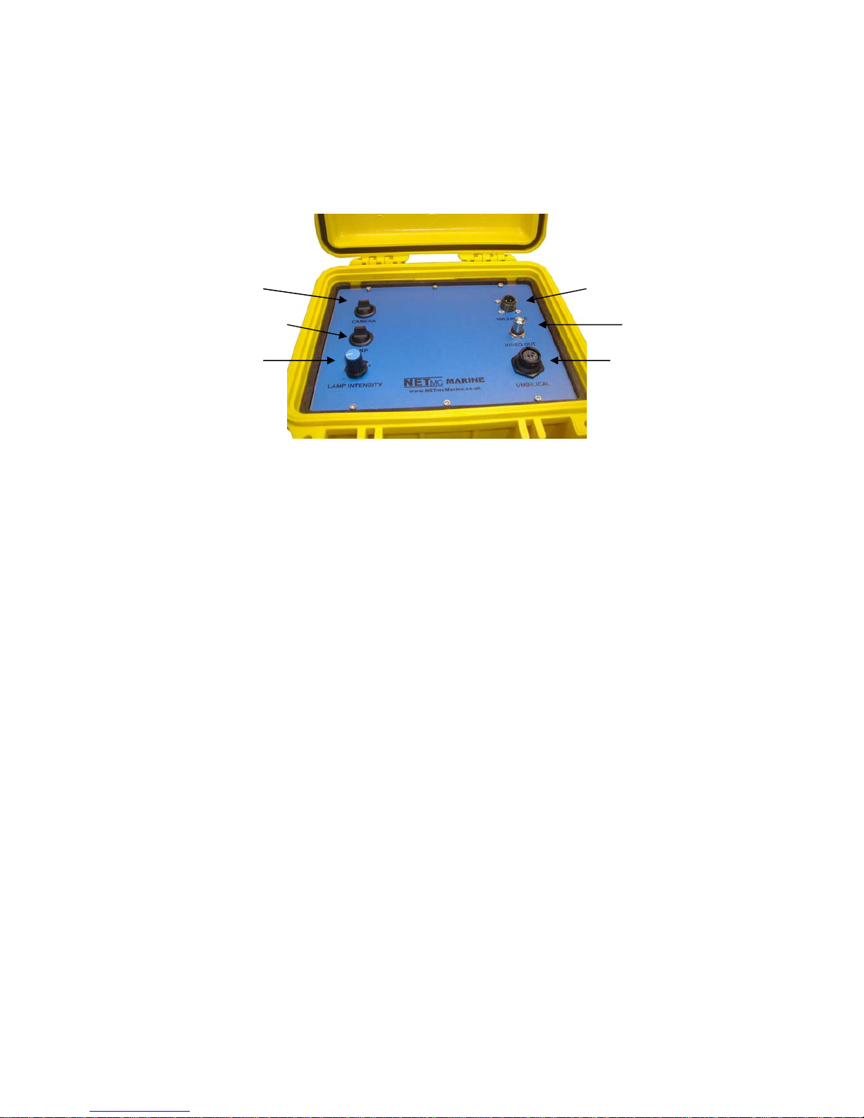
2. videoPWRpeli
2.1 Hardware Description and Connections
Switch camera on/off Connector for
p
ower
Connector for video outSwitch lam
p
on/off
Lam
p
dimmer control Connector for umbilical
When switching on, the dimmer control knob should always be set at its minimum.
This prevents damage to any connected lamp and prevents inrush surges which might
happen if no lamp is connected - which may blow fuses.
2.2 Electrical:
The units operate from 90 to 260 VAC input.
Lamp output 0-24v DC variable.
Camera output typically 24v DC
Camera signal should be via co-ax unless unit has been ordered specifically with twisted pair line
drivers – this is indicated on the product bar code.
THIS EQUIPMENT MUST BE EARTHED.
NETmcMarine videoPWR Rev3.2 4 of 15
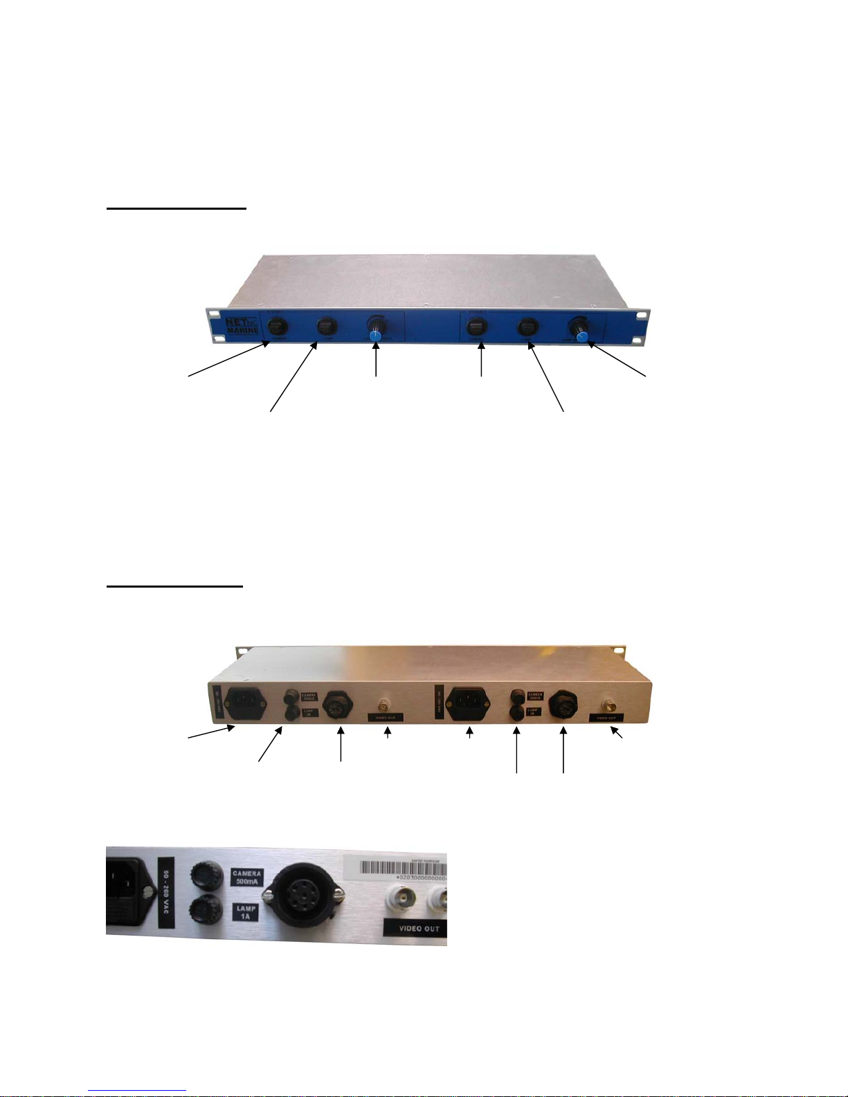
3. videoPWR dual - rackmount version
3.2 Hardware Description and Connections
Front of the unit
Camera switch 1
Lam
p
switch 1
Lamp dimmer
control 1 Camera switch 2
Lam
p
switch 2
Lamp dimmer
control 2
When switching on, the dimmer control knob should always be set at its minimum.
This prevents damage to any connected lamp and prevents inrush surges which might
happen if no lamp is connected - which may blow fuses.
Back of the unit
Example - Dual channel videoPWR to work with Novasub cameras/lamps
Connector for
p
ower 1 Video out 2Power 2
Umibilical 2
(Souriau
connector)
Camera 2
Lamp 2
Video out 1
Umibilical 1
(Souriau
connector)
Camera 1
Lamp 1
Example with Amphenol connector
(see Appendix 2)
NETmcMarine videoPWR Rev3.2 5 of 15
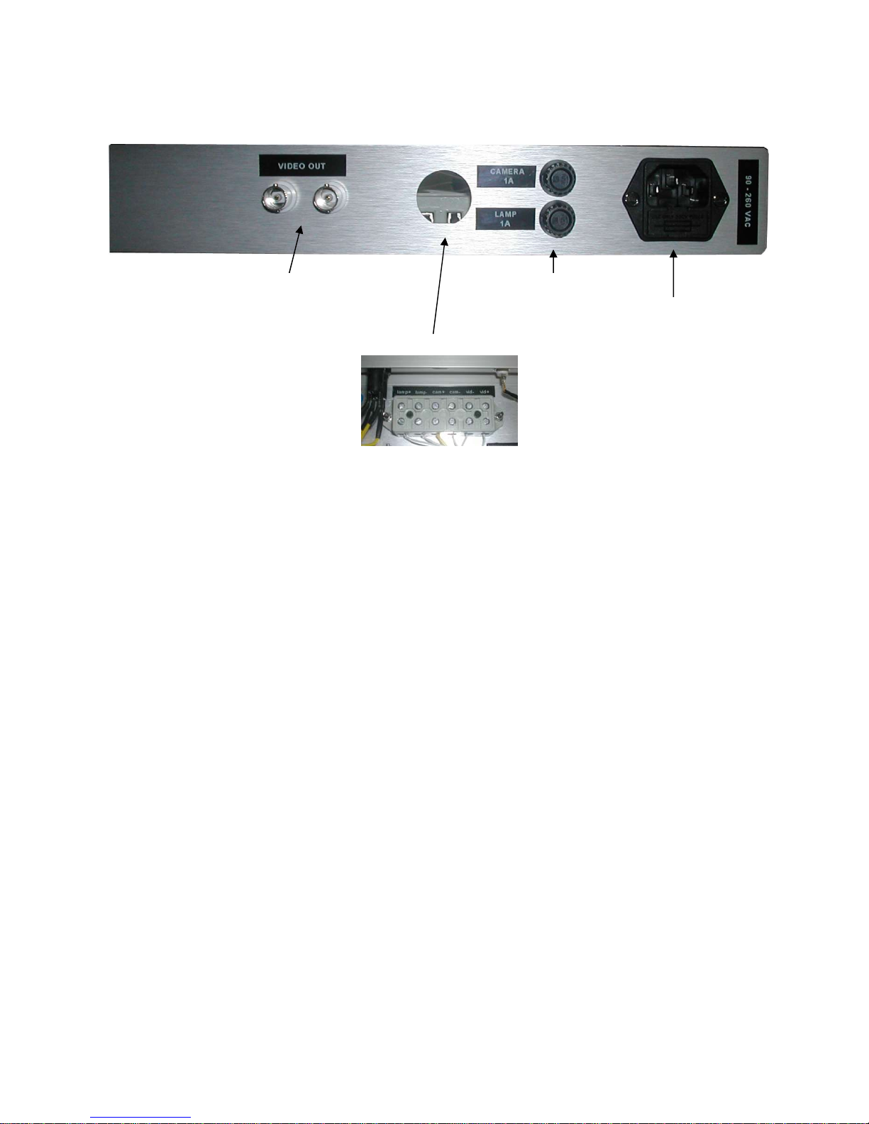
Example single channel videoPWR, to work with Bowtech cameras L3C-550-A4, lamps LED-
800-13, no umbilical connector requested:
Video
connectors Camera /
Lamp
Power Connector
Screw terminal instead of umbilical connector. See Appendix 4
3.3 Electrical:
The units operate from 90 to 260 VAC input.
Lamp output 0-24v DC variable.
Camera output typically 24v DC
Camera signal should be via co-ax unless unit has been ordered specifically with twisted pair line
drivers – this is indicated on the product bar code.
THIS EQUIPMENT MUST BE EARTHED.
NETmcMarine videoPWR Rev3.2 6 of 15

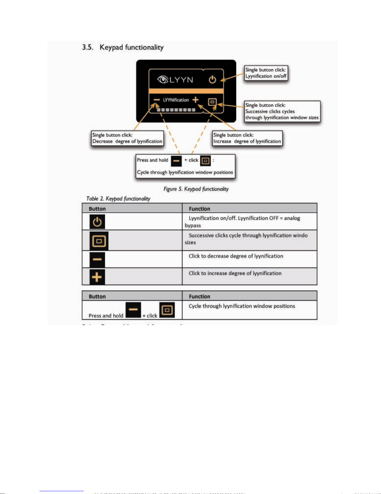
3.4 Video enhancement
Video enhancement is an optional addition to a videoPWR unit, which must be ordered at the time of
purchase.
This feature uses Lyyn Visibility Enhancement Technology to improve visibility underwater by up to
60%.
Please see Appendix 5 for more details on this feature.
4. How to contact NETmc Marine Support
Should any problems occur with your videoPWR that are not addressed by this manual please
contact our Support Team:
Email: [email protected].
Tel: +44 1771 644001
Should your call be outside office hours, please leave a message on the answering machine, which
will be forwarded to one of the support engineers. Although we cannot guarantee 24/7 availability,
we endeavour to respond as quickly as possible to any query – regardless of when the support call is
made.
NETmcMarine videoPWR Rev3.2 7 of 15

Note:
This equipment has been tested and found to comply with the limits for a Class A digital device,
pursuant to part 15 of the FCC Rules. These limits are designed to provide reasonable protection
against harmful interference when the equipment is operated in a commercial environment. This
equipment generates, uses, and can radiate radio frequency energy and, if not installed and used in
accordance with the instruction manual, may cause harmful interference to radio communications.
Operation of this equipment in a residential area is likely to cause harmful interference in which case
the user will be required to correct the interference at his own expense.
Notes:
1. Whilst every effort has been made to ensure that the information contained in this manual is
accurate, no liability can be accepted for errors and omissions.
2. Should this product be modified in any way by anyone other than a qualified NETmc Marine
employee, then NETmc Marine cannot be held liable for any consequences.
NETmcMarine videoPWR Rev3.2 8 of 15

Appendix 1
Technical Specifications
Power Requirements 110-240 Vac, 50-60 Hz
Operating Temperature 10 - 35 Degrees
Non-operating Temperature -10 - 60 Degrees
Operating Humidity 5-95% RH non-condensing
Non-operating Humidity 5-95% RH non-condensing
Operating Shock 65G, 2ms
Non-operating Shock 250G, 2ms
Operating Altitude -305m – 3,050m
Non-operating Altitude -305m – 12.200m
Operating Vibration Linear 20-300Hz, 0.75G (0 to peak)
Random 10-300 Hz, 0.004g2/Hz
Non-operating Vibration Low frequency 5-20 Hz, 0.195 inches (double amplitude)
High frequency 10-300Hz, 5.0G (0 to peak)
Dimensions - rackmount 482(W) x 41(H) x 155(D) (1U case)
Weight - rackmount 1.5 kg
Dimensions – peli version 270(L) x 246(W) x 174(H) (1300 Pelicase)
Weight – peli version 2.5 kg
Storage and shipping
After overnight road freight the units should be left at room temperature for 24 hours before powering
on.
After air freighting the units should be left at room temperature for 48 hours before powering on.
NETmcMarine videoPWR Rev3.2 9 of 15
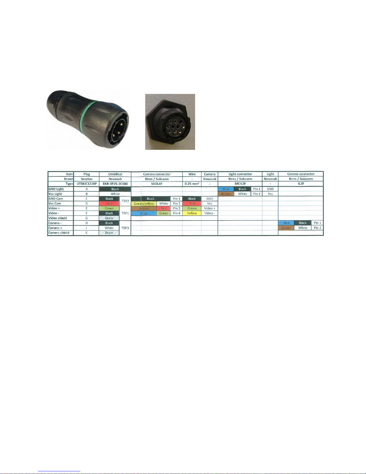
Appendix 2
Wiring Pin-Out of Souriau Umbilical Connector
Spare parts:
Umbilical: Novasub. Type DLR-3P25-2C100
Umbilical Plug: Brand Souriau, type UTS6JC1210P, RS part 191-428
Crimp pin : Souriau SM20WL3S25UK RS 233-2703
NETmcMarine videoPWR Rev3.2 10 of 15
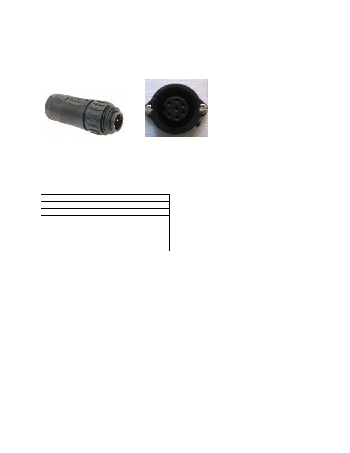
Appendix 3
Wiring Pin-Out of Amphenol Umbilical Connector
Amphenol part C01630H00610010
RS part: 540-1688
Protective cap: RS part 452-085
Pin
1 Lamp +
2 Lamp -
3 N/C
4 Video Signal
5 Video Ground
6 N/C
7 Video Power + 12v
NETmcMarine videoPWR Rev3.2 11 of 15
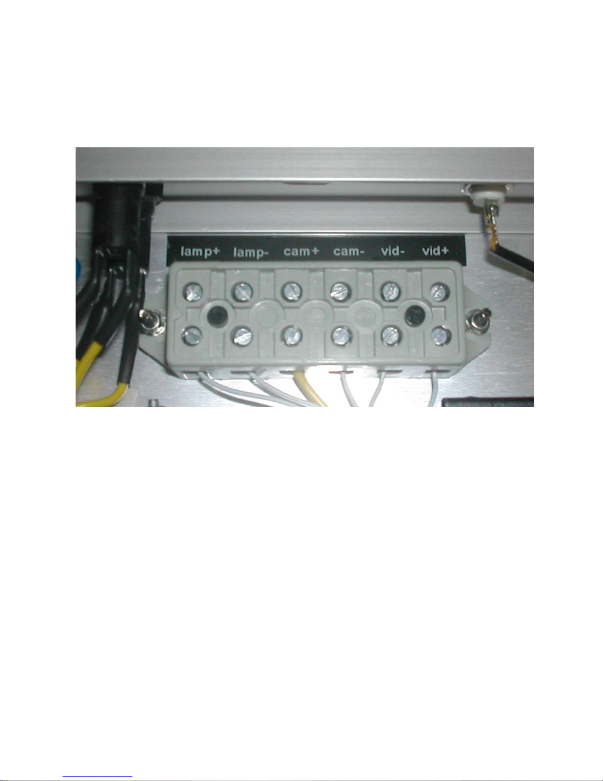
Appendix 4
Screw terminal wiring (where applicable)
NETmcMarine videoPWR Rev3.2 12 of 15

Appendix 5
LYYN Visiblity Enhancement Technology
NETmcMarine videoPWR Rev3.2 13 of 15

NETmcMarine videoPWR Rev3.2 14 of 15
NETmcMarine videoPWR Rev3.2 15 of 15
Table of contents
Popular Marine Equipment manuals by other brands


Notifier
Notifier NFX-WS series installation instructions

SLEIPNER MOTOR AS
SLEIPNER MOTOR AS Side-Power SP30Si installation manual

JL Marine
JL Marine Power-Pole Advanced Foot Switch operating instructions

Raymarine
Raymarine ST40 Quick reference guide

SurTec
SurTec Star-vox 22PCIR001 manual

NASA Marine
NASA Marine STINGRAY Series manual


