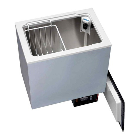
Isotherm INOX DR 49 Manual

Installation & operating instructions
Isotherm INOX marine refrigerators
Type: DR 49 & DR 65
Istruzioni per l’installazione e l’uso
Frigoriferi marini Isotherm INOX
Modelli: DR 49 & DR 65
Einbau- & Bedienungsanleitung
Isotherm INOX Marine Kühlschrank
Für Modelle: DR 49 & DR 65
Installation & Mode d’emploi
Réfrigérateur à usage marin Isotherm INOX
Pour modèles : DR 49 & DR 65
Installations- & Bruksanvisning
Isotherm INOX marinkylskåp
För typ: DR 49 & DR 65
Instrucciones de instalación y de uso
Neveras para embarcaciones Isotherm INOX
Para los modelos: DR 49 & DR 65
Installatievoorschriften en gebruiksaanwijzing
Isotherm INOX koelkasten voor maritiem gebruik
Voor type: DR 49 & DR 65
Asennus- ja käyttöohje
Isotherm INOX -venejääkaapit
Koskee malleja: DR 49 & DR 65
080428-LLG
DRman.ind
GB
I
D
F
S
E
NL
FIN
Indel Webasto Marine S.r.l.
Zona Artigianale
IT-61019 S. Agata Feltria (PU) - Italy
Tel +39 0541 848 030 Fax +39 0541 848 563
E-mail:[email protected]
www.indelwebastomarine.com

Installation & operating instructions
Table of contents
1 Introduction
1.1 General
1.2 Safety and precautions
1.3 Environmental markings
2 Operation
2.1 Temperature setting thermostat
2.2 User tips
2.3 Defrosting
3 Maintenance
3.1 Battery voltage sensor
4 Installation instructions
4.1 Ventilation
4.2 Door front
4.3 Electrical connections
4.4 Electrical wire dimensions
4.5 Inner light
4.6 Wiring diagram
5 Technical data
6 Trouble shooting
7 Installation dimensions
1
GB

1. Introduction
1.1 General
Isotherm refrigerators are specially designed to
operate in tough marine environments. They are
fi t ted with a fully hermetic, leak-free compressor,
they offer the lowest possible power consumption
and noise level. All models are simple to install. They
can withstand an angle of heel up to 30°, for a short
time. To ensure that your Isotherm fridge operates as
efficiently as possible, please follow these general
guidelines:
• Unnecessary opening of the fridge door will increase
power consumption.
• Good ventilation of the compressor and condenser
unit will reduce power consumption.
• The electrical system should be in good condition.
Inspect batteries and charging levels regularly.
Always use a separate starter battery for the engine.
Follow carefully the guidelines regarding electrical
cable areas and fuse placements.
• Keep the inside of the fridge and freezer clean and
dry. Remove any water from condensation that may
have collected in the drip tray.
• Keep the door slightly open to air the refrigerator
when leaving the boat for any length of time.
• Clean the inside of the refrigerator with lukewarm
water and a mild detergent before taking the fridge
into operation the first time.
For your own and others safety, read this first.
Danger! When connected to mains power,
ensure that the power supply is equipped with
an earth safety automatic switch, a ”ground fault
circuit interrupter”.
Danger! Never touch bare electrical wiring
connected to the AC power supply.
Do not use the device if the connector cables
show visible damage.
Never connect battery charger direct to the
refrigeration system.
A battery charger must be connected to the
battery, never direct to the refrigeration system.
Danger! In addition to acid, a newly-charged
battery contains explosive gas.
Never cover the ventilation openings for the
compressor unit.
Refrigerant may never be let out in the air.
Repair of the refrigeration circuit must be done by
a certified technician.
1.3 Environmental markings
This appliance is marked according to the European
directive 2002/96/EC on Waste Electrical and
Electronic Equipment (WEEE). By ensuring this
product is disposed of correctly, you will help prevent
potential negative consequences for the environment
and human health, which could otherwise be caused
by inappropriate waste handling of this product.
The symbol on the product, or on the documents
accompanying the product, indicates that this product
may not be treated as household waste. Instead it
shall be handed over to the applicable collection point
for recycling of electrical and electronic equipment.
Disposal must be carried out in accordance with local
environmental regulations for waste disposal.
For more detailed information about treatment,
recovery and recycling of this product,
please contact your local city office,
your household waste disposal service
or the shop where you purchased the
product.
1.2 Safety and precautions
2

2. Operation
The refrigerators are made for use at ambient tem-
parures between 0°C/32°F and +42°C/107°F.
2.1 Temperature regulation thermostat
The refrigerator is fitted with a manually operated
thermostat. This is turned clockwise to reduce
temperature and anti-clockwise to both increase
temperature and activate the on-off switch at the end
position, 0-position. A certain spring resistance is
recognized at the off position.
It is advisable to start with the thermostat in a medium
position. It is advisable to keep a temperature of 5-6°C/
41-43°F inside the refrigerator. Higher temperatures
will reduce storage time.
The ambient temperature influences the temperature
also inside the fridge. Avoid direct sunshine and other
heat sources close to the refrigerator.
The thermostat control knob is placed inside the
refrigerator, see description below.
3. Maintenance
The Isotherm DR refrigeration systems have a fully
hermetic closed cooling system and do not require any
maintenance or refilling of refrigerant.
The compressor is of mobile type and has a very high
efficiency and an outstanding life-time. The refrigerator
shall be left in the boat during the winter. (If the
temperature is below freezing point, the compressor
may not start). The maintenance is reduced to
periodically, not less than a year, cleaning of the
condenser from dust. Use a soft brush and no sharp
tools. Keep the cabinet inside clean. Use lukewarm
water and a mild detergent for cleaning the inside. Put
the doors, during not in operation periods, in their
slightly open ventilation position.
Thermostat inside on
vertical wall.
3.1 Battery voltage sensor
To protect the batteries from becoming completely
discharged, a battery voltage sensor switches off the
compressor automatically at the following levels:
System voltage V Cut out V Cut in V
12 9.6 (10.4) 10.9 (11.7)
24 21.3 (22.8) 22.7 (24.2)
If the bridge between C and P is cut off, values within
the () are valid.
3
2.2 User tips
- Load the food inside the refrigerator in such a way, air
can circulate to equalize the temperature.
- Do not cover the shelves with glass or paper etc.
- To reduce the amount of ice building up in the
evaporator, cover all liquids and moist food.
- Let all hot foods cool well before putting them into the
refrigerator.
2.3 Defrosting
The evaporator is working on below freezing
temperatures and will form frost and ice from humidity
in the air. The humidity increases with higher outside
temperature, with storage of non sealed fresh food and
liquids and the time the door is kept open. Defrosting
shall be made when the frost layer is more than 4 mm
/ 1/8” thick.
Set the thermostat in OFF position or switch off on the
ASU control panel. Store the foodstuff and the liquid as
cold as possible during the defrosting process.
Do not use sharp metal tools to remove frost or
ice. Do not re-start until the refrigerator is completely
defrosted, cleaned and dried. Empty and clean also
the plastic drip tray below the evaporator. Place towels
in the bottom of the refrigerator to collect melt water.
4 Installation instructions
Many boats have a space which is intended for a
fridge. The Isotherm Cruise fridge has been designed
to suit the general dimensions normally used for this
purpose.
The compressor should normally stand upright in the
boat, but will operate at an angle of heel up to 30° and
for short periods even more.
The INOX type refrigerators have a flush mounting
frame, three side frame, as standard.
4.1 Ventilation
It is very important that the compressor/condenser
unit is well ventilated and that cold air can enter at the
bottom, pass behind the fridge and warm air can leave
at the top in the area where it is mounted. The natural
fl o w of air from below and upwards behind the fridge
can be increased by arranging ventilation openings at
the rear.
Make sure there is a free area of 100-150 cm² / 15
- 23 sq.in. below and behind the refrigerator to allow
ventilation air to pass behind from below.
See fig.

4
4.4 Wire dimensions
Cable
area mm²
Wire
gauge #
Max cable
length in m/ft.
12V
Max cable
length in m/ft,
24V
2.5 12 2,5 / 8 5 / 16
4 12 4 / 13 8 / 26
6 10 6 / 33 12 / 66
4.3 Electrical connections/wiring
When connecting the refrigerator electrically, it is
important that following points are considered:
Always use cables of sufficient area. The area in the
following table should be regarded as a minimum.
* Always connect the refrigerator directly to the battery
or to the battery main switch on the plus circuit. Do
not connect it via the boats own control panel or
other diversions as this can cause a voltage drop in
the power supply. Use the included fuse holder with
a 15A fuse. Use 7.5A fuse in a 24 volt system. The
fuse shall be mounted on the plus cable.
4.5 Inner light
The refrigerators have inner light (LED) mounted in the
top of the cabinet.
4.2 Door front panel
The INOX models have doors in stainless steel and do
not have exchangeable door fronts.
4.6 Wiring diagram
12-24 VDC
1. Electronic unit 12/24 volt
2. Battery
3. Fan
4. Thermostat
5. Fuse 15A-12V / 7,5A-24V
6. Light LED
1
2
3
4
5
6
001284
AC/DC, 100-240 VAC & 12-24 VDC
* Connect the red cable to the positive (+) terminal
and the black to the negative (-) terminal. Use tab
type terminals for the connection to the electronic
unit and other cable connectors of sufficient size for
the cable size selected.
* Do not connect the refrigerator direct to a battery
charger. The battery charger must be connected to
the battery.
001286

5
5 Technical data
Voltage 12 or 24 volt DC / 100-240 volt AC
Power consumption when compressor is running: DR 49 & 65: 5 A at 12 V (half at 24 V)
Average consumption:
Average consumption measured at +6°C/43°F in the refrigerator
and 22°C/72°F ambient temperature.
The average consumption is much dependent on the way the
fridge is used and how well the ventilation
is working.
DR 49: 0,8 A at 12 V
DR 65: 0,9 A at 12 V
Compressor: Danfoss BD35F
Refrigerant: R134a, filling amount is printed on the sticker
inside the fridge.
Fuse: 15 A for12 volt or 7,5 A for 24 volt respec-
tively.
Isotherm refrigerators fulfil valid EMC directives and are CE-marked.
6 Fault finding
Fault Possible cause Action
Fridge not cold, compressor will
not start.
No power supply.
Battery in poor condition.
Faulty thermostat.
Faulty electronic unit.
Check that power is present at electronic unit.
Check fuse.
Check polarity on connectors and cables.
Bridge the thermostat over T-C, see wiring
diagram. If compressor starts, this indicates a
faulty thermostat. If the compressor does not
start, this indicates a faulty electronic unit or
compressor.
Contact an authorized service agent.
A possible leak in the cooling system, contact
an authorized service agent.
Compressor makes only short
start attempts.
Bad power supply, too low voltage or
voltage drop at start attempts.
Discharged batteries.
Check cables, terminals and other connec-
tions, possible verdigris or corrosion, Clean.
Charge batteries, run the engine or connect a
battery charger. Voltage must be kept above
11.0 V at start attempts.
Compressor runs but no refrig-
eration generated.
Loss of refrigerant. Leakage in pipes or
evaporator.
Pipes blocked.
Pressure and leak test. Check for pipe dam-
ages. Repair possible leak, evacuate and re-fill
refrigerant. (All this to be made by refrigeration
specialist).
Compressor runs long time but
not generating enough cold.
Bad ventilation. Condenser too warm.
Cooling fan not working
Too much frost on evaporator.
Door not closing well.
Condenser blocked by dust.
Improve ventilation for compressor.
Re-place fan.
Defrost.
Check/adjust door position and door seal.
Clean condenser.
Fuse blows. Wrong fuse size.
Faulty electronic unit.
Check fuse, 15 A-12 V / 7,5 A-24 V
Exchange electronic unit.
If a complicated fault does occur, such as requiring specialist assistance, please contact
Indel Webasto Marine S.r.l. Italy or your local marine distributor for advice.

6
Type B * H * D D - AC/DC
DR 49 INOX 400 530 510 530
DR 65 INOX 470 530 530 550
*) B x H = day opening, min dimensions
More detailed drawings of the refrigerators can
be seen on: www.indelwebastomarine.com
7 Installation dimensions

Istruzioni per l’installazione e l’uso
Indice
1 Introduzione
1.1 Generalità
1.2 Norme di sicurezza
1.3 Ambiente
2 Istruzioni per l’uso
2.1 Regolazione della temperatura con termostato
2.2 Consigli per l’uso
2.3 Sbrinatura
3 Manutenzione
3.1 Protezione per bassa tensione
4 Istruzioni per l’installazione
4.1 Ventilazione
4.2 Pannellatura dello sportello
4.3 Collegamenti elettrici
4.4 Dimensioni dei cavi elettrici
4.5 Illuminazione interna
4.6 Schema elettrico
5 Dati tecnici
6 Ricerca dei guasti
7 Misure di installazione
1
I

1. Introduzione
1.1 Generalità
I frigoriferi marini Isotherm sono progettati per
soddisfare i requisiti elevati dell’ambiente marino
in termini di prestazioni e affidabilità. Dotati di un
innovativo compressore stagno a prova di perdite,
offrono consumo elettrico e livello di rumore minimi. I
frigoriferi sono facili da installare. Possono funzionare
fi n o a un’inclinazione di 30° o, per brevi periodi,
superiore.
Per le massime prestazioni, osservare quanto segue:
• L’apertura non necessaria del frigorifero comporta un
maggiore consumo elettrico.
• Una ventilazione adeguata di compressore e
condensatore riduce notevolmente il consumo elettrico.
• L’impianto elettrico deve essere in buone condizioni.
Verificare regolarmente le batterie e il livello di carica.
Utilizzare sempre una batteria di avviamento separata
per il motore.
Attenersi alle indicazioni fornite relativamente alle
dimensioni dei cavi e ai fusibili.
• Lasciare sempre socchiuso lo sportello per consentire
l’aerazione del frigorifero qualora non venga utilizzato
per periodi più o meno lunghi.
• Prima di utilizzare il frigorifero, pulirlo internamente
con un detergente neutro e acqua tiepida.
1.2 Norme di sicurezza
• In caso di collegamento all’alimentazione a terra,
accertarsi che sia dotata di massa e salvavita per
evitare gravi lesioni personali. Non toccare eventuali
cavi elettrici danneggiati o non isolati quando è inserita
l’alimentazione a terra.
Pericolo di morte!
• È assolutamente vietato effettuare interventi nel
circuito del refrigerante.
• Non rilasciare mai il refrigerante nell’ambiente.
• Non ostruire mai il sistema di ventilazione del
frigorifero.
• Non montare il frigorifero vicino a fonti di calore quali
fornelli, caldaie, radiatori ecc.
• Montare il frigorifero in un luogo asciutto e al riparo da
spruzzi d’acqua.
• Non collegare mai il caricabatterie direttamente al
frigorifero.
Il caricabatterie deve essere collegato alla batteria.
• Oltre all’elettrolito, una batteria appena ricaricata può
contenere idrogeno gassoso esplosivo. Pericolo!
• Non conservare nel frigorifero bombolette spray
contenenti gas propellenti infiammabili.
• La riparazione dell’impianto refrigerante del frigorifero
deve essere affidata a personale qualificato.
1.3 Ambiente
Questo prodotto è conforme alla direttiva 2002/96/CE
sui rifiuti di apparecchiature elettriche ed elettroniche
(RAEE).
Il corretto smaltimento del prodotto è essenziale
per prevenire potenziali conseguenze negative per
l’ambiente e la salute.
Il simbolo su prodotto, imballaggio o relativa
documentazione indica che il prodotto non deve
essere smaltito fra i rifiuti domestici. Il prodotto deve
essere consegnato a un centro di raccolta autorizzato
per il riciclaggio delle apparecchiature elettriche ed
elettroniche. Smaltire sempre il prodotto nel rispetto
delle disposizioni ambientali locali sullo smaltimento dei
rifiuti.
Per maggiori informazioni su smaltimento, riciclaggio
e riutilizzo del prodotto, rivolgersi alle autorità locali,
al servizio di raccolta dei rifiuti locale o al rivenditore/
all’azienda presso cui è stato acquistato il prodotto.
L’imballaggio, progettato per proteggere il frigorifero e i
relativi componenti durante il trasporto, è fabbricato in
materiale riciclabile. L’imballaggio riporta i simboli del
riciclaggio e deve essere consegnato a un centro di
raccolta.
2

2. Istruzioni per l’uso
I frigoriferi sono progettati per l’uso a una temperatura
esterna compresa fra 0 e 42°C.
2.1 Regolazione della temperatura con
termostato
La temperatura del frigorifero si regola in continuo per
mezzo del termostato, che integra anche una funzione
di spegnimento se ruotato al finecorsa antiorario.
Per spegnere l’apparecchio occorre superare una
leggera resistenza della manopola. La posizione della
manopola del termostato dipende dal tipo di frigorifero,
vedere le seguenti figure.
Per regolare la temperatura, procedere come segue:
Ruotando il termostato in senso orario la temperatura
interna si abbassa e viceversa.
Si raccomanda di mantenere il frigorifero a una
temperatura di 5-6°C. La temperatura esterna
influenza quella del frigorifero, quindi può essere
difficile mantenere la temperatura interna corretta se il
frigorifero è esposto a calore e luce solare diretta.
Posizione del
termostato in DR
49 & DR 65
3
2.2 Consigli per l’uso
- Se possibile, accendere il frigorifero circa 6 ore prima
di riporvi i prodotti.
- Riporre i prodotti nel frigorifero senza ostacolare la
circolazione dell’aria al suo interno.
- Non coprire i ripiani con plastica, carta ecc.
- Per ridurre la formazione di brina nel frigorifero, non
riporre liquidi in contenitori aperti.
- Lasciare raffreddare i prodotti caldi prima di riporli nel
frigorifero.
2.3 Sbrinatura
Poiché l’evaporatore funziona a temperature inferiori al
punto di congelamento, su di esso si formano ghiaccio
e brina.
L’umidità dell’aria, la temperatura e il numero di
aperture dello sportello influenzano notevolmente la
formazione di brina.
Sbrinare sempre il frigorifero quando lo strato di
brina sull’evaporatore ha uno spessore di 3-4 mm o
superiore.
Spegnere il frigorifero ruotando il termostato in
posizione 0 Effettuare la sbrinatura quando i prodotti
possono rimanere il più possibile al fresco fuori dal
frigorifero. Non utilizzare oggetti appuntiti per
rimuovere il ghiaccio e la brina dall’evaporatore in
quanto potrebbe danneggiarsi causando perdite di
refrigerante.
Riaccendere il frigorifero solo dopo averlo sbrinato,
pulito e asciugato con cura. Estrarre, svuotare e
asciugare la vaschetta di sgocciolamento sotto
l’evaporatore. All’occorrenza, durante la sbrinatura,
sistemare un asciugamano alla base del frigorifero per
agevolare la raccolta dell’acqua.
3. Manutenzione
I frigoriferi Isotherm Drawer sono dotati di un impianto di
raffreddamento stagno che non richiede manutenzione
e rabbocco di refrigerante.
Il compressore è progettato appositamente per
applicazioni mobili per garantire un rendimento e
una durata eccellenti. In inverno il frigorifero deve
essere conservato all’interno dell’imbarcazione, ma il
compressore non funziona a temperature prossime a
0°C o inferiori. La manutenzione stagionale si limita
alla pulizia del condensatore dietro il frigorifero. In
particolare, è necessario spazzolare/aspirare tutta la
polvere accumulata per effetto della ventola. Utilizzare
una spazzola morbida e un aspirapolvere. È importante
tenere pulito l’interno del frigorifero con acqua tiepida e
sapone neutro. Quando il frigorifero è spento e in
inverno, lasciare lo sportello socchiuso in posizione di
aerazione.
3.1 Protezione per bassa tensione
Per evitare che le batterie si scarichino
eccessivamente, una protezione spegne il compressore
in caso di tensione insufficiente e lo riaccende solo
quando la tensione nell’impianto aumenta in seguito
alla ricarica delle batterie.
Tensione di sistema Spegnimento Spegnimento
12V 9,6 (10,4) V 10,9 (11,7) V
24V 21,3 (22,8) V 22,7 (24,2) V
Se si rimuove il ponticello nell’elettronica fra C e P sono
validi i valori indicati fra parentesi.
4 Istruzioni per l’installazione
Molte imbarcazioni sono dotate di un apposito vano
per il frigorifero. I frigoriferi Isotherm Cruise sono
conformi a queste “dimensioni standard”. Il frigorifero
deve sempre essere in posizione orizzontale, con
i piedini di gomma del compressore in basso. Il
compressore può funzionare fino a un’inclinazione di
30° o, per brevi periodi, superiore. Se l’inclinazione è
superiore, il compressore si disattiva e si riavvia quando
l’inclinazione diminuisce.
Non montare il frigorifero vicino a fonti di calore ed
evitare che sia esposto alla luce solare diretta.
I modelli DR 49 INOX e DR 65 INOX sono dotati di
telaio di montaggio a tre lati di serie.

4
4.1 Ventilazione
È molto importante che il compressore/condensatore
situato dietro il frigorifero sia ben ventilato in modo che
l’aria fresca possa entrare dal basso e passare dietro il
frigorifero e che l’aria calda possa fuoriuscire dall’alto o
dai lati.
Il flusso naturale dell’aria dal basso verso l’alto può
essere aumentato praticando aperture di ventilazione in
punti adatti. Le aperture devono essere di circa 100-150
cm².
Vedere la seguente figura che illustra il principio per
una corretta ventilazione.
4.2 Pannellatura dello sportello
I modelli INOX sono dotati di sportello completamente
in acciaio inox e sono sprovvisti di pannellatura dello
sportello sostituibile.
4.3 Collegamenti elettrici
Per il collegamento all’impianto elettrico
dell’imbarcazione, osservare quanto segue:
- Utilizzare sempre cavi con sezione sufficiente (vedere
le raccomandazioni nella seguente tabella).
- Utilizzare sempre cavi di rame normali o stagnati a più
conduttori, indicati per l’ambiente marino.
- Collegare il frigorifero direttamente alla batteria o al
relativo interruttore principale. Evitare il collegamento
tramite il quadro elettrico dell’imbarcazione in quanto
potrebbe causare cadute di tensione.
- Inserire a monte del frigorifero un fusibile da 15 A (12
V) o 7,5 A (24 V).
- Collegare il cavo rosso al polo positivo dell’impianto
elettrico e quello nero al polo negativo. Utilizzare un tipo
di capocorda pressato adatto alla dimensione del cavo.
- In caso di montaggio di un interruttore separato per il
frigorifero, controllare che sopporti un carico di 15 A.
Non collegare il frigorifero direttamente al caricabatterie
se non si dispone di una batteria collegata in parallelo.
4.4 Dimensioni dei cavi elettrici
Sezione in mm² Lunghezza max
cavo in m. 12V
Lunghezza max
cavo in m, 24V
2,5 2,5 5
4 4 8
6 6 12
4.5 Illuminazione interna
In tutti i frigoriferi, l’illuminazione interna (LED 12-24V)
si trova in alto.
4.6 Schema elettrico
12-24 VDC AC/DC 100-240 VAC - 12-24VDC
001284 001286
1. Elettronica da 12/24 V
2. Batteria
3. Ventilatore
4. Termostato
5. Fusibile da 15 A (12 V)/7,5 A (24 V)
6. Luce LED
1
2
3
4
5
6

5
5 Dati tecnici
Tensione di esercizio 12 o 24 VDC / 100-240 VAC 12-24 VDC
Consumo elettrico con compressore in funzione: DR 49 e DR 65: 5 A a 12 V (la metà a 24 V)
Consumo medio:
Consumo medio misurato con temperatura interna di +6°C e
temperatura esterna di 22°C.
Il consumo medio è influenzato notevolmente da modo di utilizzo
del frigorifero e tipo di ventilazione.
DR 49: 0,8 A a 12 V
DR 65: 0,9 A a 12 V
Compressore: Danfoss BD35F
Refrigerante: R134a (la capacità dell’impianto è indicata
sulla targhetta dati del frigorifero).
Fusibile: Protezione da: 15 A (12 V) o 7,5 A (24 V)
I frigoriferi soddisfano la direttiva EMC vigente e sono dotati di marchio CE.
6 Ricerca dei guasti
Difetto Possibile causa Intervento
Il frigorifero non si raffredda, il
compressore non si avvia.
Manca l’alimentazione.
Batterie in cattivo stato.
Termostato difettoso.
Centralina elettronica difettosa.
Controllare che la centralina elettronica riceva
alimentazione e tensione sufficiente, controllare
il fusibile.
Controllare se l’illuminazione interna funziona e il
compressore riceve alimentazione.
Controllare cavi, capicorda e connettori.
Controllare che la batteria si ricarichi
correttamente.
Controllare il termostato: Ponticellare T - C
con cavo separato. Se il compressore non si
avvia, probabilmente è difettosa l’elettronica.
Sostituirla. Se il compressore si avvia con il
ponticello, è difettoso il termostato.
Sostituire il termostato.
Il compressore compie solo
brevi tentativi di avviamento.
Una tensione insufficiente o una caduta
di tensione durante il tentativo di
avviamento attiva la protezione.
Batterie scariche.
Controllare cavi e collegamenti; rimuovere
eventuali tracce di ossidazione o corrosione.
Caricare le batterie, accendere il motore o
collegare il caricabatterie.
Il compressore funziona ma non
raffredda.
Perdite di refrigerante dall’evaporatore o
dalla tubatura.
Tubatura intasata.
Effettuare una prova perdite e riparare
eventuali perdite, aspirare e rabboccare la
quantità corretta di refrigerante R134a. (Questo
intervento deve essere effettuato da un tecnico.)
Il compressore funziona a
lungo ma raffredda in modo
insufficiente (efficienza ridotta).
Ventilazione insufficiente,
surriscaldamento del condensatore.
La ventola non funziona.
Troppa brina sull’evaporatore.
Lo sportello non si chiude
correttamente, lascia entrare aria calda
e umida.
Condensatore ostruito dalla polvere
Aumentare la ventilazione.
Sostituire la ventola.
Sbrinare.
Correggere la posizione dello sportello e
controllarne la guarnizione.
Pulire il condensatore.
Il fusibile salta. Fusibile errato.
Centralina elettronica difettosa.
Controllare il fusibile: 15 A (12 V)/7,5 A (24 V).
Sostituire la centralina elettronica.
In caso di difetti più complessi che richiedono assistenza specializzata, rivolgersi alla Indel Webasto Marine S.r.l. Italia o al
distributore Isotherm locale.

6
Tipo B * H * D D AC-DC
DR 49 INOX 400 530 510 530
DR 65 INOX 470 530 530 550
*) Largh. x Alt. = luce, misure minime
Disegni più dettagliati sono disponibli al sito www.indelwebastomarine
.com
7 Misure di installazione

Einbau- & Bedienungsanleitung
Inhalt
1 Einführung
1.1 Allgemeines
1.2 Sicherheitsvorschriften
1.3 Umwelt
2 Bedienungsanleitung
2.1 Temperaturregelung mit Thermostat
2.2 Anwendungshinweise
2.3 Entfrostung
3 Wartung
3.1 Spannungswächter
4 Einbauanleitung
4.1 Lüftung
4.2 Türfront
4.3 Elektrischer Anschluss
4.4 Elektrokabelmaße
4.5 Innenbeleuchtung
4.6 Schaltplan
5 Technische Daten
6 Fehlersuche
7 Einbaumaße
1
D

1. Einführung
1.1 Allgemeines
Die Bootkühlschränke von Isotherm sind in Leistung und
Ausführung an die hohen Anforderungen angepasst, die auf
See gestellt werden.
Sie verfügen über einen modernen, hermetisch abgedichteten
Kompressor, der nicht nur minimalen Stromverbrauch,
sondern auch einen extrem niedrigen Schallpegel
gewährleistet. Die Kühlschränke lassen sich einfach
einbauen. Sie vertragen eine Neigung von bis zu 30°,
vorübergehend auch mehr.
Zur Sicherstellung der optimalen Funktion sind folgende
Punkte zubeachten:
• Den Kühlschrank nicht unnötig häufig öffnen. Dadurch
erhöht sich der Stromverbrauch.
• Eine gute Belüftung von Kompressor und Kondensator
wirkt sich stark positiv auf den Stromverbrauch aus.
• Eine gut funktionierende Elektroanlage wird vorausgesetzt.
Batterien und ihren Ladezustand regelmäßig überprüfen.
Der Motor muss immer eine eigene, separate Startbatterie
haben.
Die Anweisungen bezüglich der Kabelabmessungen und
Sicherungen sind genau zu befolgen.
• Den Kühlschrank sauber und trocken halten. Eventuell
vorhandenes Kondenswasser aus der Abtropfschale
im Kühlschrank entleeren.
• Die Tür immer zur Entlüftung öffnen, wenn der Kühlschrank
über längere oder kürzere Zeiträume hinweg nicht in
Betrieb ist.
• Den Kühlschrank vor Inbetriebnahme innen mit einer
milden Seifenlauge und lauwarmem Wasser reinigen.
• Beim Anschluss an Landstrom ist die
Stromversorgung mit einer Schutzerdung und über
einen FI-Schalter anzuschließen, andernfalls besteht
große Verletzungsgefahr. Keine beschädigten oder
nichtisolierten Kabel berühren, die an das Landnetz
angeschlossen sind. Lebensgefahr!
• Es dürfen auf keinen Fall Eingriffe in den
Kühlmittelkreislauf vorgenommen werden.
• Das Kühlmittel darf nicht in die Luft gelangen.
• Darauf achten, dass die Lüftungsanlage der
Kühleinheit nicht blockiert wird.
• Den Kühlschrank nicht neben einer Wärmequelle wie
Gasherd, Heizelement usw. montieren.
• Den Kühlschrank trocken und gegen Wasserspritzer
geschützt montieren.
• Batterieladegeräte nicht direkt an die Kühleinheit
anschließen.
Batterieladegeräte müssen an die Batterie
angeschlossen werden.
• Neben der Batteriesäure kann eine frisch geladene
Batterie auch explosives Knallgas enthalten. Gefahr!
• Spraydosenverpackungen, die feuergefährliches
Treibgas enthalten, dürfen nicht im Kühlschrank
gelagert werden.
• Das Kühlmittelsystem des Kühlschranks darf nur von
befugtem Personal repariert werden.
1.2 Sicherheitsvorschriften
2
1.3 Umwelt
In Übereinstimmung mit den Anforderungen der Europäischen
Richtlinie 2002/96/EG über Elektro- und Elektronik-Altgeräte
(WEEE) ist vorliegendes Gerät mit einer Markierung
versehen. Sie leisten einen positiven Beitrag für den Schutz
der Umwelt und die Gesundheit des Menschen, wenn Sie
dieses Gerät einer gesonderten Abfallsammlung zuführen.
In unsortierten Siedlungsmüll könnte ein solches Gerät durch
unsachgemäße Entsorgung negative Konsequenzen nach
sich ziehen.
Auf dem Produkt oder der beiliegenden
Produktdokumentation ist folgendes Symbol
Einer durchgestrichenen Abfalltonne abgebildet.
Es weist darauf hin, dass eine Entsorgung im normalen
Haushaltsabfall nicht zulässig ist. Entsorgen Sie dieses
Produkt im Recyclinghof mit einer getrennten Sammlung für
Elektro- und Elektronikgeräte.
Die Entsorgung muss gemäß den örtlichen Bestimmungen zur
Abfallbeseitigung erfolgen.
Bitte wenden Sie sich an die zuständigen Behörden Ihrer
Gemeindeverwaltung, an den lokalen Recyclinghof für
Haushaltsmüll oder an den Händler, bei dem Sie dieses Gerät
erworben haben, um weiter Informationen über Behandlung,
Verwertung und Wiederverwendung dieses Produkt zu
erhalten.

2. Bedienungsanleitung
Die Kühlschränke sind für den Einsatz in
Umgebungstemperaturen zwischen 0°C und +42°C
vorgesehen.
2.1 Temperaturregelung
Mit dem Thermostat wird die Te m peratur des Kühlschranks
stufenlos geregelt. Er verfügt außerdem über eine
Abschaltfunktion, die durch Drehung gegen den Uhrzeigersinn
bis zum Anschlag aktiviert wird.
Beim Abschalten ist ein spürbarer Widerstand im Drehschalter
zu überwinden. Die Abbildungen unten zeigen, wo sich der
Thermostat-Drehschalter im jeweiligen
Kühlschrankmodell befindet. Die Temperatur wird wie folgt
geregelt: Wenn der Thermostat im Uhrzeigersinn gedreht
wird, wird der Kühlraum kälter.
Beim Drehen gegen den Uhrzeigersinn wird der Kühlraum
wärmer. Es wird empfohlen, im Kühlschrank eine Temperatur
von 5-6°C zu halten.
Die Umgebungstemperatur beeinflusst die Temperatur im
Kühlschrank.
Daher kann es schwierig sein, die richtige Temperatur im
Kühlschrank zu halten, wenn dieser Wärme und direkter
Sonneneinstrahlung ausgesetzt ist.
Platzierung des
Thermostats im DR
49 & DR 65, an der
Rückwand bei dem
Verdampfer.
3
2.2 Anwendungshinweise
- Kühlschrank möglichst 6 Stunden vor der Beladung mit
Kühlwaren einschalten.
- Waren so einladen, dass die Luft im Kühlschrank zirkulieren
kann.
- Fächer nicht mit Kunststoff oder Papier u.ä. auslegen.
- Keine unverschlossenen Flüssigkeiten in den Kühlschrank
stellen, um die Frostbildung zu verringern.
- Warme Waren abkühlen lassen, bevor sie im Kuhlschrank
platziert werden.
2.3 Entfrostung
Da der Verdampfer bei Temperaturen unter dem Gefrierpunkt
arbeitet, bilden sich Frost und Eis am Verdampfer.
Die Frostbildung wird im hohen Maße durch Luftfeuchtigkeit,
Temperatur und Häufigkeit der Türöffnung beeinflusst.
Kühlschrank regelmäßig entfrosten, wenn die Frostschicht auf
dem Verdampfer 3-4 mm oder stärker ist. Kühlschrank durch
Drehen des Thermostats auf 0-Position abschalten.Ein-/
Ausschalter in Mittelposition. Möglichst dann entfrosten, wenn
die Waren so kalt wie möglich außerhalb des Kühlschranks
gelagert werden können.
Keine scharfen Gegenstände verwenden, um Eis und
Frost vom Verdampfer zu entfernen. Dieser könnte
beschädigt werden, mit dem Austritt von Kühlmittel als
Folge.
Kühlschrank erst wieder anschalten, wenn er völlig entfrostet,
trocken und sauber ist. Tropfschale unter dem Verdampfer
herausziehen, entleeren und abtrocknen.
Bei der Entfrostung evtl. ein Handtuch unten in den
Kühlschrank legen, um Schmelzwasser aufzufangen.
3. Wartung
Isotherm Cruise Kühlschränke verfügen über ein hermetisch
abgeschlossenes Kühlsystem, das keine Wartung oder
Auffüllung von Kühlmittel erfordert.
Der Kompressor ist speziell für mobile Anwendungen
ausgelegt, er verfügt über einen besonders hohen
Wirkungsgrad und eine außergewöhnlich lange Lebensdauer.
Der Kühlschrank sollte den Winter über im Boot bleiben.
Jedoch kann der Kompressor nicht starten, wenn die
Temperatur bei 0°C oder tiefer liegt. Die saisonale Wartung
beschränkt sich auf die Reinigung des Kompressors auf der
Rückseite. Aufgrund des Lüfters sammelt der Kompressor
Staub, der abzubürsten oder abzusaugen ist. Die Arbeit wird
mit weicher Bürste und Staubsauger ausgeführt. Innen ist
der Kühlschrank sorgfältig mit lauwarmem Wasser und
einer milden Seifenlauge reinzuhalten. Im Winter, und
wenn der Kühlschrank abgeschaltet ist, muss die Tür in
Lüftungsposition offen stehen.
3.1 Spannungswächter
Um die Batterien gegen Tiefentladung zu schützen, schaltet
ein Batteriewächter den Kompressor bei zu niedriger
Spannung ab. Die Einschaltung erfolgt erst wieder, wenn die
Spannung im System durch Aufladen der Batterien erhöht
wurde.
Systemspannung V Abschaltung V Einschaltung V
12 9,6 (10,4) 10,9 (11,7)
24 21,3 (22,8) 22,7 (24,2)
Wenn die Überbrückung zwischen C und P am Elektronikteil
entfernt wird, gelten die Werte in Klammern.
4 Einbauanleitung
Viele Boote verfügen über einen Stauraum, der für den
Kühlschrank vorgesehen ist. Kühlschränke von Isotherm
haben die allgemein verwendeten Standardabmessungen.
Der Kühlschrank muss immer waagerecht stehen, mit den
Gummifüßen des Kompressors nach unten. Der Kompressor
verträgt eine Neigung von bis zu 30°, ohne sich abzuschalten,
kurzzeitig auch mehr. Bei größeren Neigungen schaltet sich
der Kompressor ab und startet wieder, wenn sich die Neigung
verringert hat.
Der Kühlschrank sollte nicht in der Nähe einer Wärmequelle
und nicht so montiert werden, dass er dem direkten
Sonnenlicht ausgesetzt ist.
DR 49 INOX & DR 65 INOX verfügen standardmäßig über
einen dreiseitigen Montagerahmen.
4.1 Lüftung
Es ist ausgesprochen wichtig, dass der Kompressor/
Kondensator an der Rückseite des Kühlschranks gut belüftet
ist, so dass kalte Luft von unten zugeführt wird, hinter dem
Kühlschrank vorbeiströmt und die erwärmte Luft nach oben
oder seitwärts abgeleitet werden kann.
Der natürliche Luftstrom von unten nach oben kann
erheblich verbessert werden, indem an geeigneten Stellen
Lüftungsöffnungen angebracht werden. Eine geeignete Größe
für die Öffnungen ist 100-150 cm².
Siehe Abb. unten mit einem Prinzip für gute Lüftung.

4.2 Türfront
Die INOX DR Modelle sind mit einer Tür komplett in Edelstahl
ausgestattet, die Türfront lässt sich nicht auswechseln.
4
4.3 Elektrischer Anschluss
Beim Anschluss an die Elektroanlage des Bootes sind
folgende Punkte unbedingt zu beachten:
• Immer einen großzügigen Kabelquerschnitt verwenden,
siehe Empfehlungen in der nachstehenden Tabelle
- Immer mehrdrähtige oder verzinnte Kupferkabel für den
Einsatz auf See verwenden.
- Den Kühlschrank direkt an die Verbrauchsbatterie oder
deren Hauptschalter anschließen. Den Umweg über
den Verteiler des Bootes vermeiden, da es hierdurch zu
unnötigem Spannungsabfall kommen kann.
- Der Kühlschrank ist mit 15 A für 12 Volt bzw. 7,5 A für 24
Volt abzusichern.
- Das rote +Kabel an die Plusseite der Elektroanlage
anschließen, und das schwarze an Minus. Die
richtigen gepressten Kabelschuhe für die gewählten
Kabelabmessungen verwenden.
- Wenn ein separater Schalter für den Kühlschrank montiert
wird, muss dieser einer Belastung von 15 A standhalten.
Der Kühlschrank darf nicht direkt an ein Batterieladegerät
angeschlossen werden, ohne dass eine Batterie
parallelgeschaltet ist.
4.4 Elektrokabelmaße
Kabelquerschnitt
mm²
Max. Kabellänge
in m, 12V
Max. Kabellenge
in m, 24V
2,5 2,5 5
4 4 8
6 6 12
4.5 Innenbeleuchtung
Die Kühlschränke sind mit einer LED Innenbeleuchtung
ausgestattet, die oben im Kühlschrank montiert ist.
1. Steuereinheit 12-24V
2. Batterie
3. Ventilator
4. Thermostat
5. Sicherung 15A-12V / 7,5A-24V
6. Beleuchtung LED
1
6
2
3
4
5
001284 001286
4.6 Schaltplan
12-24VDC AC/DC, 100-240VAC & 12-24VDC

5
5 Technische Daten
Betriebsspannung 12 oder 24 Volt DC / 100-240 Volt AC
Stromverbrauch bei laufendem Kompressor: DR 49 & DR 65: 5 A bei 12 V (Hälfte bei 24 V)
Durchschnittsverbrauch:
Durchschnittsverbrauch gemessen bei +6° im Kühlraum und 22°C
Umgebungstemperatur.
Der Durchschnittsverbrauch wird stark dadurch beeinflusst, wie der
Kühlschrank genutzt wird und wie die Lüftung
ausgeführt ist.
DR 49: 0,8 A bei 12 V
DR 65: 0.9 A bei 12 V
Kompressor: Danfoss BD35F
Kältemittel: R134a, die Füllmenge ist auf dem Typenschild des
Kühlschranks angegeben.
Sicherung: Abzusichern mit: 15 A -12 Volt bzw. 7,5 A - 24 Volt
Die Kühlschränke erfüllen die geltenden EMC-Direktiven und tragen die CE-Zulassung.
6 Fehlersuche
Fehler Mögliche Ursache Maßnahme
Der Kühlschrank wird nicht kalt.
Der Kompressor läuft nicht an.
Keine Stromversorgung.
Batterien in schlechtem Zustand.
Falscher Thermostat.
Fehler an der Elektronikeinheit.
Überprüfen, ob Strom und ausreichend Spannung bis
zur Elektronikeinheit vorliegen, Sicherung kontrollieren.
Wenn die Innenbeleuchtung funktioniert, ist Strom bis
zum Kompressor vorhanden.
Kabel, Kabelschuhe und Anschlussklemmen
überprüfen.
Überprüfen, ob die Batterieladung funktioniert.
Kontrolle Thermostat: T-C mit einem separaten Kabel
überbrücken. Wenn der Kompressor nicht anläuft,
ist die Elektronikeinheit wahrscheinlich defekt. In
diesem Fall austauschen. Wenn der Kompressor
mit Überbrückung anläuft, ist der Thermostat defekt.
Thermostat austauschen.
Der Kompressor unternimmt nur
kurze Startversuche.
Zu schwache Spannung, durch
Spannungsabfall beim Startversuch
wird der Spannungswächter aktiviert.
Die Batterien sind entladen.
Kabel und Anschlüsse überprüfen und von eventuell
vorhandenen Oxid- und Korrosionsablagerungen
befreien.
Batterien laden, Motor laufen lassen oder
Batterieladegerät anschließen.
Der Kompressor läuft, erzeugt aber
keine Kälte.
Kühlmittelverlust, Undichtigkeit am
Verdampfer oder in der Rohrleitung.
Rohrleitung verstopft.
Dichtigkeitsprüfung vornehmen und eventuell
vorhandene Undichtigkeiten reparieren, mit Vakuum
absaugen und die richtige Menge R134a auffüllen.
(Eine solche Maßnahme ist von einem Fachmann
durchzuführen.)
Der Kompressor läuft lange, erzeugt
aber nur wenig Kälte. Schwache
Leistung.
Schlechte Belüftung, der Kondensator
wird warm.
Der Lüfter läuft nicht.
Zu viel Frost am Verdampfer.
Kühlschranktür schließt nicht richtig, lässt
warme feuchte Luft herein.
Der Kondensator hat sich mit Staub
zugesetzt.
Belüftung verbessern.
Lüfter austauschen.
Entfrosten.
Position und Dichtung der Tür überprüfen.
Kondensator reinigen.
Sicherung geht kaputt. Falsche Sicherung.
Elektronikeinheit kaputt.
Sicherung überprüfen, 15 A-12 V / 7,5 A-24 V.
Elektronikeinheit austauschen.
Bei komplizierteren Fehlern, die einen Spezialisten erfordern, ist Kontakt zu Indel Webasto Marine S.r.l. Italien oder zum
örtlichen Isotherm-Händler aufzunehmen.

6
Typ B * H * D1 D1 - AC/DC
DR 49 INOX 400 530 510 530
DR 65 INOX 470 530 530 550
*) BxH = lichte Öffnung, Mindestmaß
Detailliertere Zeichnungen unter www.indelwebastomarine.com
7 Einbaumaße

Installation & Mode d’emploi
Sommaire
1 Introduction
1.1 Généralités
1.2 Consignes de sécurité
1.3 Environnement
2 Mode d’emploi
2.1 Réglage de température par thermostat
2.2 Conseils d’utilisation
2.3 Dégivrage
3 Entretien
3.1 Contrôle de tension
4 Consignes d’installation
4.1 Ventilation
4.2 Porte
4.3 Connexions électriques
4.4 Sections de câble
4.5 Éclairage intérieur
4.6 Schéma électrique
5 Fiche technique
6 Recherche de panne
7 Cotes d’installation
1
F
This manual suits for next models
1
Table of contents
Languages:
Other Isotherm Marine Equipment manuals
Popular Marine Equipment manuals by other brands

Kongsberg
Kongsberg HiPAP 502 instruction manual

FLIR
FLIR M-Series installation guide

GUIDANCE MARINE
GUIDANCE MARINE RadaScan View Installer's guide

probrand
probrand ProTechT XMME-KIT00 Installation instructions and owner's manual

GENASYS
GENASYS 60XL user guide

Kongsberg
Kongsberg Simrad CS90 Reference manual