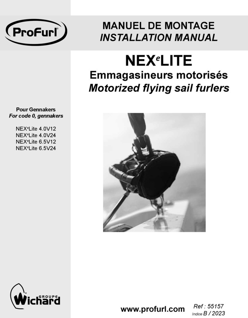
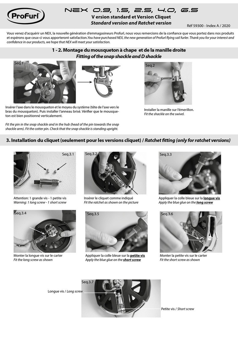
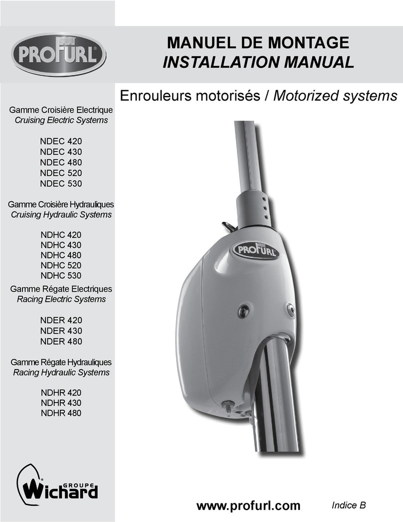
ProFurl C260 User manual

MANUEL DE MONTAGE
INSTALLATION MANUAL
Enrouleurs de Génois C260 / C260 Headsail Reeng-Furling System
mm ins
A 150 5 29/32’’
B 575 1’10 5/8’’
C 26 1 1/32’’
D 115 4 17/32’’
E 56 2 13/64’’
F 56 2 13/64’’
G 67 2 41/64’’
H 50 1 63/64’’
www.profurl.com

www.profurl.com
RÉCEPTION DU MATÉRIEL
Le matériel voyage toujours aux risques et périls du
destinataire.Il y a donc lieu d’effectuer une vérication
dès réception, et émettre éventuellement toutes réserves
pour exercer le cas échéant tous recours à l’encontre des
transporteurs dans les délais réglementaires.
RECEIPT OF GOODS
All goods must be checked on delivery and the purchaser
should claim from the carrier within seven days in the event
of loss or damage.
I Précautions Préliminaires
I a) L’enrouleur PROFURL C260 est destiné à des monocoques.
Il n’est ni conçu pour multicoques, ni pour être utilisé pour une
trinquette.
I b) Il appartient à l’installateur de vérier ou de faire vérier par
une personne compétente que l’étai sur lequel l’enrouleur sera
installé est en bon état. En cas de doute, remplacer l’étai.
II Outillage nécessaire pour le montage
L’enrouleur de génois C260 a été conçu pour être installé
facilement. Pour son montage, quelques outils nécessaires:
- un décamètre
- un mètre ou réglet
- un pied à coulisse
- un petit marteau
- une scie à métaux
- une queue à rat
Vous devez vous procurer un cordage tressé de
diamètre 6 mm, d’une longueur égale à 3 fois
la longueur du bateau + 2 mètres.
Ce cordage sera utilisé à la fois en tant
que drisse et drosse d’enroulement.
III Principe de montage
Quelque soit la terminaison d’étai, le principe de montage reste
toujours le même:
La bride (7) est toujours serré en haut du sertissage inférieur. Si
le diamètre du sertissage inférieur de l’étai excede 9 mm, serrer la
bride à fond et la repercer en se guidant sur le trou existant à Ø
- 1mm.
Le C260 n’est pas conçu pour être monté sur une terminaison
inférieure d’étai type Norsemann®, Sta-Lok® ou équivalent.
Si il est nécessaire de recourir à ce type de terminaison, prévoir
une terminaison sertie en bas de l’étai et monter l’embout type
Norseman®, Sta-Lok® ou équivalent en tête de l’étai.
ATTENTION ! Lorsque le C260 est monté sur un étai
comportant un ridoir, celui-ci devra être vérrouillé avec des moyens
appropriés pour qu’il ne puisse en aucun cas être entraîné en
rotation lors de l’utilisation de l’enrouleur.
IV Identification des gaines de C260
L’enrouleur C260 comprend:
- 1 gaine inférieure longueur 0.50 m (14)
- 3 gaines de longueur de 2 mètres (17) si l’enrouleur a été livré en
6.50 m, ou
- 4 gaines de longueur de 2 mètres (17) si l’enrouleur a été livré en
8.50 m.
I Preliminary cautions
I a) The PROFURLC260 is designed for light displacement monohulls.
It is not designed to be used on multihulls, or for a staysail.
I b) If the age of your forestay exceeds seven years, replacement
may be necessary. If in doubt replace the stay.
II Tools needed for installation
The PROFURL C260 is designed to be easily tted. The following
tools are required for the installation:
- a measuring tape
- a measuring ruler
- a callipers gauge
- a small hammer
- a metal saw
- a round le
Please purchase a braided line with a 6 mm (1/4‘‘) diameter with a
length equal to three times
the boat length + 2 meters / 6 ft.
The line will be used for both halyard and furling line.
III Fitting principle
The principle to attach the drum onto the stay is always the same,
whichever type of lower terminal is found at the bottom of the stay
(eye or turnbuckle):
The clamp (7) is always attached onto the lower swage terminal (not
the forestay wire), and should be as close as possible from the upper
end of the lower swage terminal. Should the diameter of the swage
terminal exceeds 9 mm / 3/8’’ please tighten the screws to close the
clamp and drill at Ø minus 1mm / 1/16’’ through the existing hole.
The C260 is not designed to be tted over a Norsemann®, Sta-Lok®
or similar type of lower terminal. Should such a terminal be used,
please have a swage terminal at the bottom end the stay, and use
the Norseman®, Sta-Lok® or similar at the upper end of the stay.
CAUTION ! When the PROFURL C260 is to be fitted on to a
forestay with a turnbuckle, please make sure the turnbuckle is
properly and safely locked so that it can not turn when operating the
system.
IV Checking the C260 extrusions
The PROFURL C260 includes:
- 1 lower extrusion (14) 0.50 m / 1’ 7 43/64’’ long
- 3 extrusions, each 2 meter / 6’ 6 3/4’’ long (17) if the system has
been delivered in 6.50 meter / 21’ 3 3/4’’ total length or
- 4 extrusions, each 2 meter / 6’ 6 3/4’’ long (17) if the system had
been delivered in 8.50 meter / 27’ 10 ‘‘ total length.

www.profurl.com
V -Mise à longueur des gaines
Seq 1
2 cas peuvent se présenter :
- montage sur un bateau mâté → mesurer la
longueur «L » de l’étai entre les extrémités de
sertissage avec un décamètre tel que décrit,
xer une drisse sur un point solide à l’avant du
bateau et la tendre, décapeler la terminaison
inférieure de l’étai.
- montage sur un bateau non mâté ou étai
au sol → mesurer la longueur «L » de
l’étai entre les extrémités de sertissages avec
un décamètre tel que décrit.
La longueur totale des gaines «G » sera:
G = L - 250 mm si vous disposez d ’un
bateau transportable sur remorque
(possibilité de replier l’enrouleur pour le
transport).
G = L - 200 mm dans le cas contraire
ATTENTION ! Recouper l’une des gaines
de 2 mètres pour obtenir une longueur
totale de gaines (inclus la gaine de 0.50 m)
égale à «G ».
!Ne pas couper la gaine de 0.50 m (14).
VI - Identication des éclisses
Le C260 comporte 3 différents types
d’éclisses (voir dessin):
- 1 éclisse supérieure (21) qui sera montée
en haut de la gaine supérieure (recoupée
dans la plupart des cas).
- 3 (enrouleurs en 6,50 m) ou 4 (enrouleurs en
8,50 m) éclisses de raccordement (18).
- 1 éclisse inférieure (15) livrée montée en
bas de la gaine de 0,50 m (14).
VII - Montage de l’enrouleur
Seq 2
Déboîter vers le haut la boîte à réa (25) du
carénage (24).
Enler l’étai à travers l’ouverture du carénage
(24).
Passer le cordage ø 6 mm dans la poulie de la
boîte à réa (25) et enler ses 2 extrémités vers
le bas dans l’ouverture du carénage (24).
VII -Fitting the system
Step 2
Remove upwards the halyard block (25)
from the sheave housing (24).
Slide the stay through the sheave housing
(24).
Fit the 6 mm / 1/4” halyard downward
through the sheave housing (24) and
through the sheave box (25).
VI -Checking the bearings /
torquelinks
The PROFURL C260 has three different types of
bearings / torque links. Please refer to drawing
for identication.
•1 upper bearing / torque link (21) which will be
tted at the top of the upper extrusion (having
been re-cut in most cases)
•3 (if system purchased in length of 6.5 m
/21‘ 3/4’’) intermediate bearing / torque links
(18)
or 4 (if system was purchased in length of
8.5 m /27’ 10 ”)
•1 lower bearing / torque link (15) which is
supplied already tted at the lower end of the
0.50-meter /
1’ 7 43/64 ’’ extrusion (14).
V -Cutting extrusions to length
Step 1
There are 2 possibilities:
- when tting on a standing mast → measure the
length «L » with a measuring-tape as shown in
drawing, secure a halyard on a strong point at
the bow and tension it,
remove the forestay from the chainplate.
- when tting on a mast or forestay lying on
the ground → measure the length «L » with a
measuring-tape as shown.
Total length “G” of the extrusions will be:
G =L - 250 mm /10“ if you intend to split
your set of extrusions (mainly to trail your
boat).
G= L - 200 mm / 7 7/8’’ in other cases.
CAUTION! one of the 2 meter / 6‘ 6 3/4”
extrusions may have to be cut to it your
existing forestay length.
! The 0.50-meter /1’ 7 43/64’’ lower extrusion
(14) length must not be shortened or cut.

www.profurl.com
Seq 3
Enfoncer un pion d’alignement (19) sur la
gaine (17) coupée, du côté de la coupe, en
la laissant dépasser de 11 mm.
Step 3
Hammer in an alignment pin (19) into the
cut end (cut side) of the upper extrusion
(17), leaving it protruding by 11 mm / 7/16 ”.
Seq 4
Enler l’extrémité inférieure de l’étai à travers la
gaine (17) coupée, du côté de la coupe.
Emboîter les 2 demi éclisses supérieures
(21) sur l’extrémité coupée de la gaine (17).
Step 4
Slide the lower end of the stay into the upper
extrusion (17) at cut end.
Fit the 2 half bearings/torque links (21) into the
top (cut end) of the upper extrusion (17).
Seq 5
Enler le cordage ø 6 mm et dans la gorge de
droite (tribord) vers le bas de l’enrouleur.
Vérier la libre circulation du cordage dans la
gorge.
Note: la ralingue de gauche (bâbord) sera
réservée à la ralingue de la voile.
Emboîter la boite à réa (24) sur l’éclisse
supérieure (21).
Step 5
Slide the 6 mm / 1/4” halyard into the
starboard (right) side groove of the extrusion
(17).
Check that it can run free in the groove.
Note: the port (left) side groove will be used
for the luff tape of the sail.
Fit the sheave housing (24) over the two
upper half-bearings/torque links (21).

www.profurl.com
Seq 6
Monter un pion d’alignement (19) à l’extrémité
d’une gaine de 2 mètres (17), en le laissant
dépasser de 25 mm.
Enler l’étai à travers la gaine de 2 m (17).
Monter les 2 demi éclisses de raccordement
(18).
Raccorder les différentes gaines (17) entre
elles en les emboîtant sur les éclisses (18) et le
pion d’alignement (19).
Enler le cordage vers le bas de l’enrouleur
en le passant dans la gorge de droite
(tribord).
Renouveler l’opération pour chaque gaine
de 2 m (17).
Monter la gaine de 0.50 m (14) en bas de
la dernière gaine de 2 m.
Seq 7
Les 2 demi-éclisses inférieures (15) sont
livrées montées en bas de la gaine de 0.50 m
(14): enlever l’adhésif et vérier qu’elles
sont enlées jusqu’à la butée.
Seq 8
Enler le cordage qui sort de la gorge
tribord (droite) à travers le conduit du
bloqueur (3) situé au-dessus du tambour (2),
et le tirer.
Seq 9
Emboîter le tambour (2) sur le bas de la
gaine inférieure (14) et l’éclisse (15).
Monter et serrer la vis (6).
Step 8
Slide the halyard through the stopper (3)
conduit of the drum (2), pull a few extra meter/ft
of halyard out of the drum.
Step 9
Slide the drum (2) over the bottom end of the
0.50-m / 1’7 43/64’’ lower extrusion (14).
Fit drum screw (6).
Step 6
Hammer in an alignment pin (19) until
protruding out by 25 mm (1‘’) into the upper end
of a 2 meter / 6’ 6 3/4 ’’ extrusion (17).
Slide the stay through a 2-meter / 6’ 6 3/4’’
extrusion (17).
Fit the intermediate two half bearings / torque
links (18).
Fit a 2 meter / 6’ 6 3/4” extrusion over the two
half bearing /torque links (18) and alignment pin
(19).
Fit the halyard through the starboard (right)
groove.
Repeat the above steps to assemble all 2-meter
/ 6’ 6 3/4’’ extrusions (17) together, and the 0.50
m / 1’ 7 43/64” lower extrusion (14).
Step 7
The lower bearing (15) is delivered tted at
the lower end of the 0.50m / 1’7 43/64’’ lower
extrusion (14). Remove adhesive tape that holds
it in place. Check it is inserted into the extrusion
until stop.

www.profurl.com
Seq 10
Enler le bras guide (7). Monter et serrer la
bride sur le sertissage inférieur de l’étai tel
qu’indiqué: 3 mm maxi du bord de sertissage.
Joindre provisoirement les 2 extrémités du
cordage.
Sur un bateau mâté, remettre l’étai en place.
Seq 11
Passer le cordage à travers le guide drisse
(7) et dans une poulie de guidage - (non fournie)
- positionnée sur le bateau (balcon avant ou rail
de fargue par exemple) pour que le cordage
attaque le tambour à 90 ° et à mi-hauteur de
celui-ci.
Régler l’orientation de la bride (7) sur le
sertissage de l’étai pour que le cordage otte le
moins possible sur le guide.
Step 10
Slide the drum cage (7) over the lower swage
terminal. Tighten the clamp as shown:
maximum 3 mm / 1/8 ” from the upper edge
of the terminal. Tie a knot to temporarily attach
both ends of the line.
On a boat with a standing mast, t the stay
onto the chainplate.
Step 11
Pull the line through the lead of the drum cage
(7) and through a lead block (not supplied) which
may be positioned on the toe rail or the pulpit.
Ensure that the line reaches the drum and mid
height with a 90° angle.
Adjust the angle of the drum cage (7) in
line with the boat’s axis to minimise the
chafe of the line on the lead.
VIII -Utilisation de l ’enrouleur
Seq 12
Attacher sur le point de drisse de la voile le
brin du cordage qui redescend extérieurement
à la gorge.
Seq 13
Accrocher le point d’amure de la voile sur
la manille (5) située sur le dessus du tambour
(2)
Seq 14
Hisser la voile en engageant la ralingue dans la
gorge bâbord (gauche) et en tirant sur le brin du
cordage qui sort à travers le tambour, le guide
drosse et la première poulie, étarquer et fermer
le bloqueur pour coincer la drisse.
VIII -Using the system
Step 12
Attach the line that comes from the top of system
onto the head of the sail.
Step 13
Attach the tack of the sail onto the shackle
(5) located on the drum (2).
Step 14
To hoist the sail insert the luff tape into the port
(left) side groove, pull on the tail of the line that
goes through the drum, the lead and the rst lead
block, tension the luff, and close the stopper.

www.profurl.com
Seq 15
Pour charger le tambour en cordage, faire
tourner l’enrouleur à la main pour enrouler
la voile aussi serrée que possible.
Note: veillez au sens de l’enroulement de
la voile pour que la bande anti-UV soit le
cas échéant à l’extérieur de la voile enroulée.
Attacher la voile enroulée avec une garcette ou
un petit sandow, et tirer le cordage
pour enlever complètement le cordage du
tambour. Ajouter 3 ou 4 tours en faisant
tourner l’enrouleur dans le même sens que
précédemment.
Step 15
To load the drum with the line (furling
line), turn the system by hand to completely
furl the sail as tight as possible.
Note: if your sail has an anti UV strip, the
furled sail should have the anti UV strip
outwards.
Secure the clew of the sail with rope or shock
cord to prevent it from unfurling, and pull the line
to completely empty the drum. Add an extra 3 or
4 turns of line in the opposite direction to that of
the furled sail.
Seq 16
Accrocher les écoutes au point d’écoute de
la voile.
Installer des poulies de renvoi (non fournies) et
renvoyer le cordage vers le cockpit.
Seq 17
Pour dérouler la voile, tirer sur l’écoute,en
relâchant le cordage de manœuvre.
Pour enrouler la voile, lâcher l’écoute en
tirant le cordage de manœuvre.
Pour enrouler partiellement, bloquer le
cordage de manœuvre lorsque la surface de
la voile souhaitée est obtenue et reborder
l’écoute.
Attention :
- pendant le déroulement, freinez le cordage de
manœuvre.
- pendant l’enroulement de la voile, ne laissez
jamais la voile faseyer en grand, mais conservez
toujours une légère tension sur l’écoute.
Seq 18
Pour affaler la voile :
- Enrouler entièrement la voile, la maintenir
enroulée avec une garcette ou un petit sandow
et démonter les écoutes.
- Tirer sur le cordage pour vider entièrement le
tambour.
- Faire tourner l’enrouleur à la main pour que le
cordage soit enroulé dans le même sens que la
voile enroulée, avec le même nombre de tours
que la voile.
- Liberer l’amarage du point d’écoute de la voile
et tirer simultanément sur le cordage et sur la
voile.
- Ouvrir le bloqueur (3) et affaler la voile.
Step 16
Attach the sheets onto the clew of the sail.
Remove the rope/shock cord.
Fit the furling blocks (not supplied) and lead the
furling line through to the cockpit.
Step 17
To unfurl the sail, pull the sheet by releasing the
furling line.
To furl the sail, pull the furling line by releasing
the sheet.
To reef the sail, attach the furling line when
the expected sail area is reached, and trim the
sheeting angle.
Caution:
-Do not unfurl the sail without controlling the
furling line.
-To reef or furl the sail pull the furling line by
placing a slight drag onto the sheet to prevent
the sail from excessive ogging.
Step 18
To lower the sail:
•Completely furl the sail, tie the clew with a rope
or shock cord, and remove the sheets from the
clew.
•Pull the furling line to get the drum completely
empty.
•Turn the system by hand to ll the drum with
line in the same direction as that of the furled
sail, with the same amount of turns as the sail.
•Remove the rope /shock cord from the clew
and pull simultaneously on the sail and the line
to completely unfurl the sail.
•Open the stopper (3) and lower the sail.

www.profurl.com
Ref: P29FGB08
WICHARD PACIFIC Pty Ltd
Unit 13, 2 Bishop Street
St Peters NSW 2044, Australia
Tel : + 61 2 9516 0677
Fax : + 61 2 9516 0688
Toll free number from Australia: 1800 639 767
WICHARD, Inc
148a Bryce Blvd
Fairfax VT 05454 USA
Tel : +1 401 683 5055
Fax :+1 802 655 4689
Toll free number: + 1 800 852-7084
WICHARD France
Support technique / Hotline
33 rue de l’Etoile du matin
44600 Saint Nazaire, France
Tel +33 (0)2 51 76 00 35
Fax +33 (0)2 40 01 40 43
CONDITIONS DE GARANTIE
Sans préjudice de la garantie légale, votre enrouleur PROFURL est garanti 10 (dix) ans à partir de la date de sa mise en service, la facture d’achat au revendeur
ou au constructeur faisant foi.
La garantie se limite au remplacement ou à la réparation en nos ateliers des pièces reconnues défectueuses.
La garantie disparaît immédiatement et complètement si le client modie ou fait réparer sans l’accord de Wichard le matériel fourni. La réparation, la modication
ou le remplacement des pièces pendant la période de garantie ne peuvent avoir pour effet de prolonger le délai de garantie du matériel.
La garantie ne couvre pas les dommages consécutifs à un mauvais montage, à une utilisation inappropriée ou abusive, à un accident ou à toute fortune de
mer.
VERIFICATIONS IMPERATIVES
Il appartient à l’utilisateur de vérier ou de faire vérier par une personne compétente que :
- la longueur du guindant de la voile est correcte, ni trop longue ni trop courte
- les xations de l’enrouleur à la base de l’étai sont correctement réalisées
- les différentes vis sont correctement serrées
- la drisse, une fois la voile hissée, est correctement tendue
- le Multitop est correctement installé et serré
- le diamètre de l’axe de xation fourni avec l’enrouleur correspond bien à celui de l’axe d’origine
Les ennuis consécutifs à ces défauts de montage ou d’utilisation, souvent constatés, ne sont pas couverts par la garantie.
PROCEDURE A SUIVRE EN CAS D’APPEL EN GARANTIE
En cas d’impossibilité de faire constater par une personne compétente la nature des dommages, le client prendra contact directement avec WICHARD S.A.
- France.
La ou les pièce(s) défectueuse(s) devra (devront) impérativement être retournée(s) pour inspection à WICHARD S.A.S (France), à WICHARD, Inc aux USA ou
à WICHARD PACIFIC Pty Ltd, port aux frais du client, dans les 14 (quatorze) jours suivant le constat de l’avarie.
En cas de réexpédition du matériel depuis un pays tiers, les frais de dédouanement éventuels correspondant à l’entrée en France ou aux USA restent à la
charge du client.
Au cas où le client exige une réexpédition des pièces avant réception des pièces défectueuses par WICHARD S.A.S (France), WICHARD Inc (USA) ou
WICHARD PACIFIC Pty, celles-ci seront facturées et payables avant l’expédition, règlement par carte bancaire, transfert bancaire ou tout autre moyen. Si la
responsabilité de WICHARD est reconnue, WICHARD remboursera le client dans les meilleurs délais.
LIMITED WARRANTY
Your PROFURL reeng-furling system is warranted for a period of 10 (ten) year from the date of purchase against parts and materials.
This warranty is limited to the repair and replacement of defective parts by an authorized PROFURL dealer and only after the written consent of WICHARD
S.A.S (France), WICHARD Inc, or WICHARD PACIFIC (addresses below).
The warranty is void if the system is modied or repaired prior written consent of WICHARD S.A.S (France), WICHARD Inc or WICHARD PACIFIC.
This warranty covers only the WICHARD parts and materials. Any accidental damage or expenses are not covered by the warranty.
This warranty does not cover damages caused by a system which was installed or used improperly, damaged by collision, or any act of God.
In the event of a warranty claim, WICHARD’s liability is limited to the value of the system at the date of purchase. Packaging costs, shipment or custom char-
ges are at customer’s expense.
OWNER SHOULD CHECK OR HAVE CHECKED BY A SKILLED PERSON THE FOLLOWING
After installation of the system the customer must check the following:
• the sail luff is cut at the correct length
• the locking devices attaching the drum mechanism are properly secured
• all screws are tightened
• the halyard is tight when the sail is hoisted
• the Wrapstop is properly installed as shown in this manual
• the diameter of the clevis pin supplied with the WICHARD’s system is correct with the forestay terminal
WHICH PROCEDURE SHOULD YOU FOLLOW IN CASE OF WARRANTY CLAIM?
• In case it is impossible for the owner to have the damage checked by a skilled person, the owner will contact WICHARD S.A.S (France), WICHARD, Inc
(USA) or WICHARD PACIFIC Pty Ltd. Please see address below.
• The defective part should be returned at owner’s expenses to WICHARD S.A.S (France), WICHARD Inc or WICHARD PACIFIC Pty Ltd within 14 (fourteen)
days after the damage occured to the system.
• In case the parts are shipped from a country outside France, USA or Australia, custom duties for return to WICHARD should be prepaid by the owner.
• In case the owner will demand urgent replacement of part before the defective part is received by WICHARD, the replacement part will be charged to the
owner, and paid before shipping (credit cards accepted). In case WICHARD’s responsibility is nally acknowledged, WICHARD will refund the owner.
• No replacement part purchased from a PROFURL dealer will be refunded to the owner.
• In the normal warranty procedure, the parts will be returned to the owner, shipping and customs at owner’s expenses.
Table of contents
Other ProFurl Marine Equipment manuals
Popular Marine Equipment manuals by other brands

Boss marine
Boss marine MR1520W user manual

Aquatic
Aquatic AQ-DM-6UBT DIGITAL MEDIA LOCKER User & installation manual

Teletek electronics
Teletek electronics SensoIRIS WSST IS Installation instruction

Raymarine
Raymarine ST60 Tridata Setup & operation

AUDAC
AUDAC ALTI 4 Series User & installation manual

Raymarine
Raymarine H6 owner's manual