NASA Marine STINGRAY Series User manual

NASA MARINE LTD
BOULTON ROAD
STEVENAGE
HERTS SG1 4QG
(01438) 354033
STINGRAY RANGE
ECHO
SOUNDER
BY
DESIGNED AND
MANUFACTURED
IN ENGLAND
RoHS
2002/95/EC


USING YOUR STINGRAY DUAL ALARM ECHO SOUNDER
GENERAL
Your depth sounder has been designed to give good results, even under
adverse conditions, but to obtain the very best from your instrument, the
following hints should be read carefully and followed as far as practicable.
A)
B)
The position of the instrument should be at least 2ft. (61cms) away from
the craft’s magnetic compass.
To reduce the possibility of induced interference from the engine’s
generator and/or ignition system, choose a position as far away from
the engine as possible and run the cable from the transducer as far as
practicable from the engine. Do not cut the transducer cable. But stow
any excess away from any possible source of electrical interference.
NOTES ON ELECTRICAL INTERFERENCE
External electrical interference is characterised by persistent, random flashes
around the scale which obscure the true depth reading on the depthsounder.
This is caused by large amplitude voltage “spikes” generally associated with the
engine’s alternator and/or ignition system which has not been properly
suppressed. These “spikes” may find their way into the sensitive amplifier
section of the depthsounder in two ways:
A)
B)
Through the craft’s common power supply or
Through direct radiation from the source of interference.
The effects of radiated interference will be very much reduced if the
recommendations in 1 (b) are followed. Should the interference still be apparent
try reducing the “GAIN” control which discriminates against interference whilst
still allowing adequate signal strength from the transducer.
CONNECTING THE EXTERNAL POWER SUPPLY
The instrument will operate from a supply of 10-16 volts DC.
Current consumption is typically 130mA.
Each instrument is supplied with a 3 pin plug and power cable which fits into a
special socket at the rear of case. Connect the power lead into the ship’s power
supply, brown (positive+) and blue (negative-).
UNDER NO CIRCUMSTANCES SHOULD A POWER SUPPLY
HIGHER THAN 16V BE CONNECTED

SITING OF THE TRANSDUCER
The transducer can be mounted in three ways:
A)
B)
C)
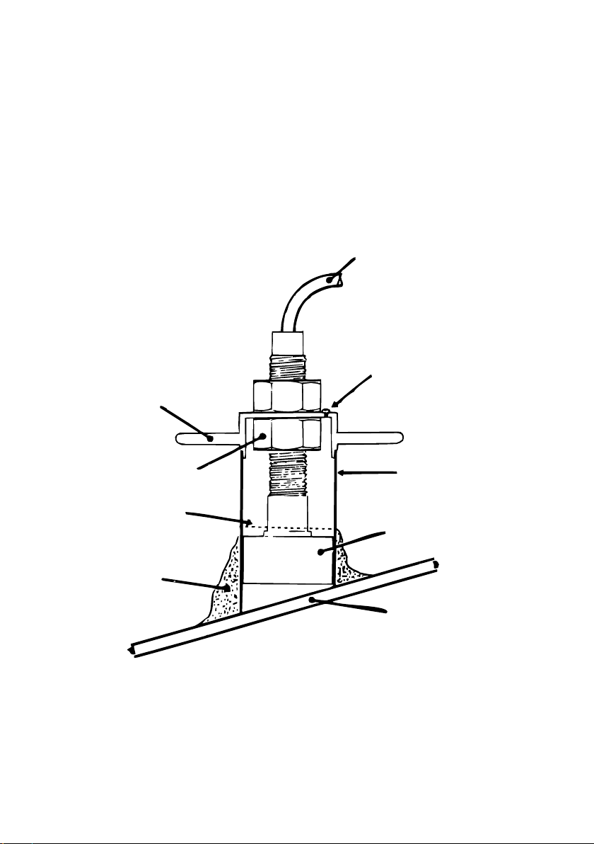
Using an in-hull transducer mounting kit available from your dealer or
direct from NASA Marine see reverse for details
The transducer face can be bonded directly to the inside of the hull.
(Some energy is lost to the hull but the loss in performance is, for most
G.R.P. hulls, hardly noticeable)
A transom mount is available from your dealer or direct from NASA Marine.
Whichever is selected the best location still has to be found.
Select a position below the water level where the transducer will point
substantially towards the sea bed and where the transducer and cable are kept
well clear of interference generating equipment. This position should be well
clear of large masses of bubbles or cavitation which would disrupt the signal.
To test the suitability of the location, press a little sticky chewing gum on the
surface of the transducer and stick it down to the inside of the hull (it may be
necessary to remove dirt and oily residue first). The unit can then be tested. If the
location is satisfactory the chewing gum can be removed and the transducer
mounted in the in-hull kit following the installation instructions or the face glued
down with quick setting epoxy. (Note: Do not shorten the transducer cable).
It is important that the face of the transducer is thoroughly bonded down to the
hull. A single air bubble will cause a considerable loss in performance.
The transducer or the place of mounting must be kept entirely free of any
antifouling compound as this can also affect the performance of the unit.
OPERATING CONTROLS
The stingray echo sounder has only four control knobs.
Top left is the deep water alarm.
Top right is the shallow water alarm. When the vessel enters deep or shallow
water corresponding with either of the preset window positions an audible
alarm will sound.
The bottom left hand knob operates; on/off, A=0-25 mtr range, B=0-100 mtr range.
The bottom right hand knob operates the “GAIN” control.
USE OF THE GAIN CONTROL
In general terms, the sensitivity of the instrument should be increased by rotating
the “GAIN” control clockwise for deep water and reduce for shallow. However,
this is by no means always necessary and experience will soon determine a
satisfactory compromise where the setting need not be altered. Because of the
large increase in transmit power built into current instruments, in very shallow
water more than one echo (i.e. rebound - echoes) are certain to occur. Reducing
the gain in this case will make interpretation of the display much easier.

IN HULL TRANSDUCER KIT
Fit your echo sounder with a NASA in-hull transducer kit. This contains all the
components required to install a standard transducer within the hull of a glass
fibre constructed vessel and is accompanied by comprehensive illustrated
instructions.
Suitable for all standard 1½”(38mm) diameter echo sounder transducers.
NOTE: THIS INSTRUMENT IS SIMPLY AN AID TO NAVIGATION AND SHOULD
NOT BE CONSIDERED AS A SUBSTITUTE FOR GOOD SEAMANSHIP.
COAXIAL CABLE
SELF TAPPING SCREW
TUBE
TRANSDUCER
HULL
FILLER
OIL LEVEL
ADDITIONAL NUT
HOUSING CAP


Declaration of Conformity
NASA Marine Ltd declare this product is in compliance with the essential requirements of
R&TTE directive 1995/5/EC.
The original Declaration of Conformity certificate can be requested at info@nasamarine.com
THIS PRODUCT IS INTENDED FOR USE ONLY ON NON SOLAS VESSELS
IMPORTANT READ THIS BEFORE
UNPACKING INSTRUMENT
LIMITED WARRANTY
Prior to unpacking this instrument read and fully understand the installation instructions.
Only proceed with the installation if you are competent to do so. Nasa Marine Ltd. will
not accept any responsibility for injury or damage caused by, during or as a result of
the installation of this product. Any piece of equipment can fail due to a number of
causes. Do not install this equipment if it is the only source of information and its failure
could result in injury or death. Instead return the instrument to your retailer for full credit.
Remember this equipment is an aid to navigation and not a substitute for proper
seamanship. This instrument is used at your own risk, use it prudently and check its
operation from time to time against other data. Inspect the installation from time to time
and seek advice if any part thereof is not fully seaworthy.
Nasa Marine Ltd. warrants this instrument to be substantially free of defects in both
materials and workmanship for a period of one year from the date of purchase.
Nasa Marine Ltd. will at its discretion repair or replace any components which fail in
normal use within the warranty period. Such repairs or replacements will be made at
no charge to the customer for parts and labour. The customer is however responsible
for transport costs. This warranty excludes failures resulting from abuse, misuse,
accident or unauthorised modifications or repairs. In no event shall Nasa Marine Ltd.
be liable for incidental, special, indirect or consequential damages, whether resulting
from the use, misuse, the inability to correctly use the instrument or from defects in
the instrument. If any of the above terms are unacceptable to you then return the
instrument unopened and unused to your retailer for full credit.
Name
Address
Dealer Name
Address
Date of Purchase
Proof of purchase may be required for warranty claims.
Nasa Marine Ltd.
Boulton Road, Stevenage, Herts SG1 4QG England
Table of contents
Other NASA Marine Marine Equipment manuals
Popular Marine Equipment manuals by other brands

Lars Thrane
Lars Thrane LT-3100 User & installation manual

ADVANSEA
ADVANSEA Speed s400 user manual

Sailmon
Sailmon E4 installation manual

Garmin
Garmin GSD 21 - GPS Receiver Remote Sonar Sensor installation instructions

Yacht Devices
Yacht Devices YDNB-07N user manual

Clarion
Clarion CMS3 Owner's manual & installation manual

Elmdene
Elmdene INT400 instruction sheet

Teleflex Marine
Teleflex Marine BayStar installation manual

Federal Signal Corporation
Federal Signal Corporation StreamLine LP4 Installation and service instructions

GME
GME RCU9200 series instruction manual

Klaxon
Klaxon Nexus 105 installation instructions

LST
LST 45681-277 Specification sheet