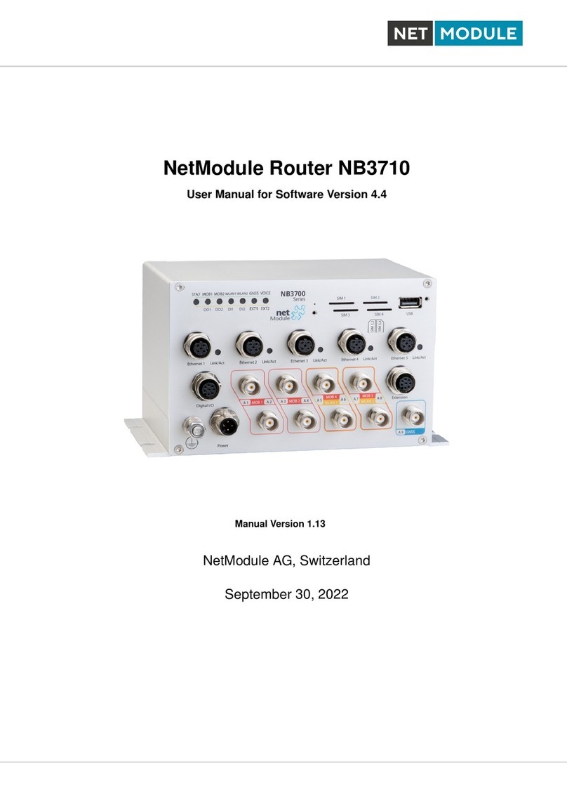
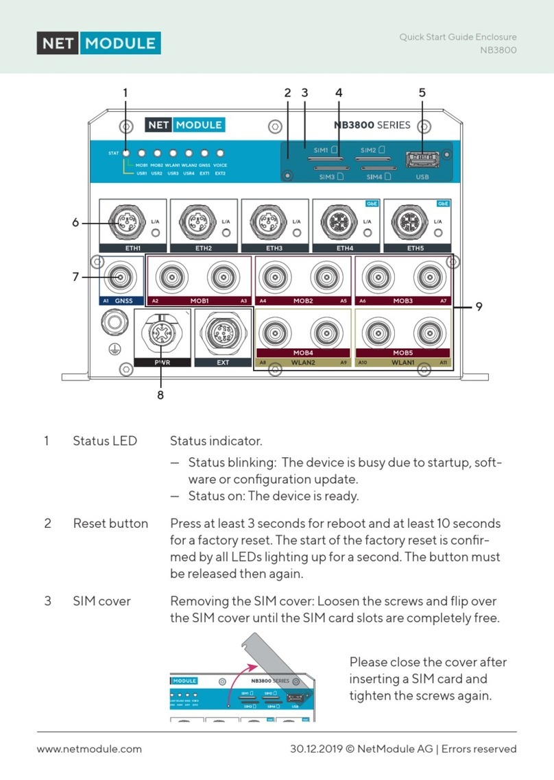
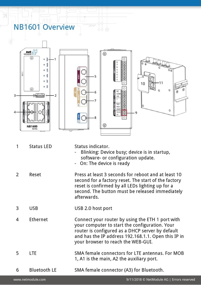
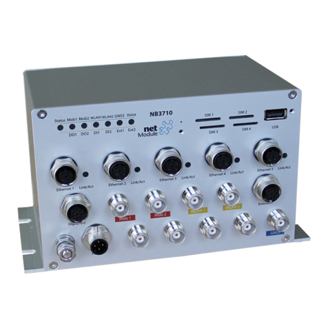
NetModule NB3720 User manual

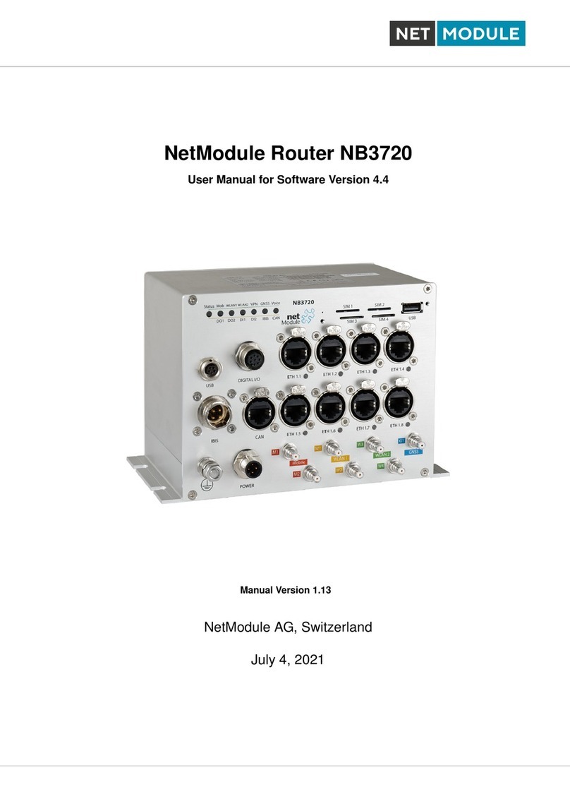
NetModule Router NB3720
User Manual for Software Version 3.8
Manual Version 1.5
NetModule AG, Switzerland
October 24, 2017

Contents
1 Welcome to NetModule 3
2 Conformity 4
2.1 Safety Instructions .............................. 4
2.2 Declaration of Conformity .......................... 5
2.3 Waste Disposal ................................ 5
2.4 National Restrictions ............................. 5
2.5 Open Source Software ............................ 6
3 Specifications 7
3.1 Features .................................... 7
3.2 Operating Elements .............................. 7
3.3 Interfaces ................................... 10
3.3.1 Overview ............................... 10
3.3.2 USB 2.0 Host Port .......................... 11
3.3.3 Ethernet Connectors ......................... 11
3.3.4 Power ................................. 12
3.3.5 Digital Inputs and Outputs ..................... 13
3.3.6 CAN Port ............................... 14
3.3.7 IBIS Port ............................... 15
4 Installation 17
4.1 Environmental Conditions .......................... 17
4.2 Installation of the Router .......................... 17
4.3 Installation of the SIM Card ......................... 17
4.4 Installation of the WLAN Antennas ..................... 18
4.5 Installation of the Local Area Network ................... 18
4.6 Installation of the Power Supply ....................... 18
5 Configuration 19
5.1 First Steps ................................... 19
5.1.1 Initial Access ............................. 20
5.1.2 Recovery ................................ 21
2

NB3720 User Manual 3.8
5.2 HOME ..................................... 22
5.3 INTERFACES ................................ 25
5.3.1 WAN .................................. 25
5.3.2 Ethernet ................................ 31
5.3.3 Mobile ................................. 37
5.3.4 WLAN ................................. 42
5.3.5 USB .................................. 48
5.3.6 Serial Port ............................... 51
5.3.7 Digital I/O .............................. 54
5.3.8 GNSS ................................. 55
5.4 ROUTING ................................... 58
5.4.1 Static Routes ............................. 58
5.4.2 Extended Routing .......................... 60
5.4.3 Multipath Routes ........................... 62
5.4.4 Mobile IP ............................... 63
5.4.5 Quality Of Service .......................... 66
5.4.6 Multicast ............................... 68
5.5 FIREWALL .................................. 69
5.5.1 Administration ............................ 69
5.5.2 Adress/Port Groups ......................... 69
5.5.3 Rules .................................. 70
5.5.4 NAPT ................................. 72
5.6 VPN ...................................... 75
5.6.1 OpenVPN ............................... 75
5.6.2 IPsec .................................. 81
5.6.3 PPTP ................................. 87
5.6.4 GRE .................................. 90
5.6.5 Dial-In ................................. 91
5.7 SERVICES .................................. 93
5.7.1 SDK .................................. 93
5.7.2 DHCP Server .............................104
5.7.3 DNS Server ..............................106
5.7.4 NTP Server ..............................108
5.7.5 DynDNS ................................109
5.7.6 E-Mail .................................111
5.7.7 Events .................................112
5.7.8 SMS ..................................113
5.7.9 SSH/Telnet Server .......................... 116
5.7.10 SNMP Agent .............................118
5.7.11 Web Server ..............................123
5.7.12 Redundancy ..............................124
5.7.13 Voice Gateway ............................126
3

5.8 SYSTEM ...................................133
5.8.1 System .................................133
5.8.2 Authentication ............................137
5.8.3 Software Update ...........................140
5.8.4 Module Firmware Update ......................141
5.8.5 Software Profiles ...........................141
5.8.6 Configuration .............................142
5.8.7 Troubleshooting ............................146
5.8.8 Keys and Certificates .........................148
5.8.9 Licensing ...............................153
5.8.10 Legal Notice ..............................154
5.9 LOGOUT ...................................155
6 Command Line Interface 156
6.1 General Usage .................................156
6.2 Print Help ...................................157
6.3 Getting Config Parameters .......................... 158
6.4 Setting Config Parameters .......................... 158
6.5 Getting Status Information ..........................159
6.6 Scanning Networks ..............................160
6.7 Sending E-Mail or SMS ............................160
6.8 Updating System Facilities ..........................160
6.9 Manage keys and certificates ......................... 161
6.10 Restarting Services ..............................161
6.11 Debug System ................................. 162
6.12 Resetting System ............................... 163
6.13 Rebooting System ...............................163
6.14 Running Shell Commands ..........................163
6.15 Working with History .............................164
6.16 CLI-PHP ...................................164
7 Technical Support 170
8 Legal Notice 171
A Appendix 173
A.1 Abbrevations .................................173
A.2 System Events .................................175
A.3 Factory Configuration ............................178
A.4 SNMP VENDOR MIB ............................179
A.5 SDK Examples ................................ 188
4

NB3720 User Manual 3.8
List of Figures
5.1 Initial Login .................................. 20
5.2 Home ..................................... 22
5.3 WAN Links .................................. 25
5.4 WAN Settings ................................. 28
5.5 Link Supervision ............................... 29
5.6 Ethernet Ports ................................ 31
5.7 Ethernet Link Settings ............................ 32
5.8 VLAN Management ............................. 33
5.9 LAN IP Configuration ............................ 35
5.10 SIMs ...................................... 37
5.11 WWAN Interfaces ............................... 40
5.12 WLAN Management ............................. 42
5.13 WLAN Configuration ............................. 44
5.14 WLAN IP Configuration ........................... 46
5.15 USB Administration ............................. 48
5.16 USB Device Management .......................... 49
5.17 Serial Port Administration .......................... 51
5.18 Serial Port Settings .............................. 52
5.19 Digital I/O Ports ............................... 54
5.20 Static Routing ................................. 58
5.21 Extended Routing ............................... 60
5.22 Multipath Routes ............................... 62
5.23 Mobile IP ................................... 65
5.24 Firewall Groups ................................ 69
5.25 Firewall Rules ................................. 70
5.26 NAPT Administration ............................ 72
5.27 Inbound NAPT ................................ 73
5.28 OpenVPN Administration .......................... 75
5.29 OpenVPN Configuration ........................... 76
5.30 OpenVPN Client Management ........................ 79
5.31 IPsec Administration ............................. 82
5.32 IPsec Configuration .............................. 83
5.33 PPTP Administration ............................ 87
5

5.34 PPTP Tunnel Configuration ......................... 88
5.35 PPTP Client Management .......................... 89
5.36 Dial-in Server Settings ............................ 91
5.37 SDK Administration ............................. 98
5.38 SDK Jobs ...................................100
5.39 DHCP Server .................................105
5.40 DNS Server ..................................106
5.41 NTP Server ..................................108
5.42 Dynamic DNS Settings ............................109
5.43 E-Mail Settings ................................ 111
5.44 SMS Configuration .............................. 114
5.45 SSH and Telnet Server ............................ 116
5.46 SNMP Agent .................................119
5.47 Web Server ..................................123
5.48 VRRP Configuration .............................124
5.49 Voice Gateway Administration ........................126
5.50 Voice Gateway Endpoint Configuration ................... 128
5.51 Voice Gateway Routing Configuration ....................131
5.52 System ..................................... 133
5.53 Regional settings ...............................136
5.54 User Accounts .................................137
5.55 Remote Authentication ............................139
5.56 Manual File Configuration ..........................142
5.57 Automatic File Configuration ........................ 143
5.58 Factory Configuration ............................144
5.59 Log Viewer ..................................146
5.60 Tech Support File ............................... 147
5.61 Keys and certificates .............................148
5.62 Certificate Configuration ...........................150
5.63 Licensing .................................... 153
List of Tables
3.1 NB3720 variants ............................... 7
3.2 NB3720 Status Indicators .......................... 9
3.3 NB3720 Interfaces ............................... 10
3.4 USB 2.0 Host Port Specification ....................... 11
6

NB3720 User Manual 3.8
3.5 Pin Assignments of M8 USB Connector ................... 11
3.6 Ethernet Port Specification ......................... 11
3.7 Pin Assignments of RJ45 Fast Ethernet Connectors ............ 12
3.8 Pin Assignments of RJ45 Gigabit Ethernet Connectors .......... 12
3.9 Power Connector Specifications ....................... 13
3.10 Pin Assignments of Power Connector .................... 13
3.11 Isolated Digital Outputs Specification .................... 13
3.12 Isolated Digital Inputs Specification ..................... 14
3.13 Pin Assignments of Digital Inputs and Outputs .............. 14
3.14 CAN Port Specification ............................ 15
3.15 Pin Assignments of RJ45 CAN Connector ................. 15
3.16 IBIS Port Specification ............................ 15
3.17 Pin Assignments of 4-pole Circular Plastic Connectors (CPC) for IBIS . 16
4.1 Operating Conditions ............................. 17
5.17 IEEE 802.11 Network Standards ....................... 43
5.33 Static Route Flags .............................. 59
5.69 SMS Control Commands ........................... 103
5.75 SMS Number Expressions ..........................113
5.103Certificate Sections .............................. 149
5.104Certificate Operations ............................ 149
A.1 Abbreviations .................................175
A.2 System Events .................................177
A.3 SDK Examples ................................ 190
7

1. Welcome to NetModule
Thank you for purchasing a NetModule Router. This document should give you an
introduction to the router and its features. The following chapters describe any aspects
of commissioning the device, installation procedure and provide helpful information
towards configuration and maintenance.
Plese further imformation such as sample SDK script or configuration samples also in
our wiki on http://wiki.netmodule.com.
8

2. Conformity
This chapter provides general information for putting the router into operation.
2.1. Safety Instructions
NetModule routers must be used in compliance with any and all applicable national
and international laws and with any special restrictions regulating the utilization of the
communication module in prescribed applications and environments.
We would like to point out that only the original accessories, shipping with the router,
must be used in order to prevent possible injury to health and damage to appliances and
to ensure that all the relevant provisions have been complied with. Unauthorized mod-
ifications or utilization of unapproved accessories may void the warranty. The routers
must not be opened. However, it is possible to replace any pluggable SIM cards even
during operation.
All circuits connected to the interfaces of the router must comply with the requirements
of Safety Extra Low Voltage (SELV) circuits and have to be designed for indoor use only.
Interconnections must not leave the building nor penetrate the body shell of a vehicle.
Possible antenna circuits must be limited to over-voltage transient levels below 1500
Volts according to IEC 60950-1, TNV-1 circuit levels using safety approved components.
NB3720 routers shall only be used with a certified (CSA or equivalent) power supply
which must have a limited and SELV circuit output. They are basically designed for
indoor use. Do not expose the communication module to extreme ambient conditions
and protect the communication module against dust, moisture and high temperature.
We remind the user of the duty to observe the restrictions concerning the utilization of
radio devices at petrol stations, in chemical facilities or in the course of blasting works
in which explosives are used. Switch off the communication module when traveling by
plane.
You need to pay heightened attention when using the communication module close to
personal medical devices, such as cardiac pacemakers or hearing aids. NetModule routers
may also cause interference in the nearer distance of TV sets, radio receivers and personal
computers.
Avoid any installation of the antenna during a lightning. Always keep a distance of more
than 40 cm from the antenna in order to reduce exposure to electromagnetic fields below
the legal limits. This distance applies to λ
4- and λ
2-antennas. Larger distances may apply
to antennas with higher gain.
Any Ethernet cabling must be shielded, the Ethernet section of this manual provides
9

NB3720 User Manual 3.8
more information.
Devices with WLAN interface may be operated only with applicable Regulatory Domain
configured.
Cellular antennas attached to the router must have an antenna gain of equal or less than
2.5 dBi. If an extension cable is used to attach the antenna, the antenna gain may be
higher by the amount of cable attenuation.
We highly recommended creating a copy of a working system configuration. It can
be downloaded using the Web Manager and easily applied to a newer software release
afterwards as we generally guarantee backward compatibility.
2.2. Declaration of Conformity
NetModule hereby declares that under our own responsibility that the
routers comply with the relevant standards following the provisions of
the Council Directive 1999/5/EC. The signed version of the Declara-
tions of Conformity can be found on the NetModule web page.
2.3. Waste Disposal
In accordance with the requirements of the Council Directive
2002/96/EC regarding Waste Electrical and Electronic Equipment
(WEEE), you are urged to ensure that this product will be segregated
from other waste at end-of-life and delivered to the WEEE collection
system in your country for proper recycling.
2.4. National Restrictions
This product may be generally used in all EU countries (and other countries following
the EU directive 1999/5/EC) without any limitation except for the countries mentioned
below. Please refer to our WLAN Regulatory Database for getting further national radio
interface regulations and requirements for a particular country.
10

NB3720 User Manual 3.8
2.5. Open Source Software
We inform you that NetModule products may contain in part open-source software.
We are distributing such open-source software to you under the terms of GNU General
Public License (GPL)1, GNU Lesser General Public License (LGPL)2or other open-
source licenses3. These licenses allow you to run, copy, distribute, study, change and
improve any software covered by GPL, Lesser GPL, or other open-source licenses with-
out any restrictions from us or our end user license agreement on what you may do
with that software. Unless required by applicable law or agreed to in writing, software
distributed under open-source licenses is distributed on an "AS IS" basis, WITHOUT
WARRANTIES OR CONDITIONS OF ANY KIND, either express or implied.
To obtain the corresponding open source codes covered by these licenses, please contact
our technical support at router@support.netmodule.com.
Acknowledgements
This product includes:
•PHP, freely available from http://www.php.net
•Software developed by the OpenSSL Project for use in the OpenSSL Toolkit
(http://www.openssl.org/)
•Cryptographic software written by Eric Young ([email protected])
•Software written by Tim Hudson ([email protected])
•Software written Jean-loup Gailly and Mark Adler
•MD5 Message-Digest Algorithm by RSA Data Security, Inc.
•An implementation of the AES encryption algorithm based on code released by
Dr Brian Gladman
•Multiple-precision arithmetic code originally written by David Ireland
•Software from The FreeBSD Project (www.freebsd.org)
1Please find the GPL text under http://www.gnu.org/licenses/gpl-2.0.txt
2Please find the LGPL text under http://www.gnu.org/licenses/lgpl.txt.
3Please find the license texts of OSI licenses (ISC License, MIT License, PHP License v3.0, zlib License)
under http://opensource.org/licenses
11

3. Specifications
3.1. Features
Currently, the following variant of NB3720 is available:
Model LTE WLAN CAN IBIS
NB3720-L2WCI-G l2x l l
Table 3.1.: NB3720 variants
Note: LTE models include support for UMTS/EDGE/GPRS. LTE models can be
equipped with a supplementary VOICE (-V) or GNSS (-G) option.
This model has following basic functionality:
•Galvanically isolated power supply
•8 Ethernet (2 Gigabit Ethernet, 6 Fast Ethernet)
•1 USB 2.0 (host)
•2 digital inputs
•2 digital outputs
•4 SIM card slots
•IBIS Wagenbus (slave)
•CAN
Due to its modular approach, the NB3720 router and its hardware components can be
arbitrarily assembled according to its indented usage or application. Please contact us
in case of special project requirements.
3.2. Operating Elements
The following table describes the NB3720 status indicators. The color of the LED
represents the signal quality for wireless links.
lred means low
lyellow means moderate
lgreen means good or excellent
12

NB3720 User Manual 3.8
Label Color State Function
Status lblinking The device is busy due to startup, software or configu-
ration update.
lon The device is ready. The captions of the top bank apply.
lon The device is ready. The captions of the bottom bank
apply.
Mob1 lllon Mobile connection 1 is up.
lblinking Mobile connection 1 is being established.
moff Mobile connection 1 is down.
WLAN1 lllon WLAN1 connection is up.
lblinking WLAN1 connection is being established.
moff WLAN1 connection is down.
WLAN2 lllon WLAN2 connection is up.
lblinking WLAN2 connection is being established.
moff WLAN2 connection is down.
VPN lon VPN connection is up.
moff VPN connection is down.
GNSS lon GNSS is turned on and a valid NMEA stream is avail-
able.
lblinking GNSS is searching for satellites.
moff GNSS is turned off or no valid NMEA stream is avail-
able.
Voice lon A voice call is currently active.
moff No voice call is active.
DO1 lon Normally open output port 1 is closed.
moff Normally open output port 1 is open.
DO2 lon Normally closed output port 2 is closed.
moff Normally closed output port 2 is open.
DI1 lon Input port 1 is set.
moff Input port 1 is not set.
13

NB3720 User Manual 3.8
Label Color State Function
DI2 lon Input port 2 is set.
moff Input port 2 is not set.
IBIS lon IBIS interface is up
moff IBIS interface is down
CAN lon CAN interface is up
moff CAN interface is down
Table 3.2.: NB3720 Status Indicators
14

NB3720 User Manual 3.8
3.3. Interfaces
3.3.1. Overview
Label Panel Function
SIM 1 Front SIM 1, it can be assigned dynamically to any modem by
configuration.
SIM 2 Front SIM 2, it can be assigned dynamically to any modem by
configuration.
SIM 3 Front SIM 2, it can be assigned dynamically to any modem by
configuration.
SIM 4 Front SIM 3, it can be assigned dynamically to any modem by
configuration.
USB Front USB 2.0 host port, can be used as USB device server or for
software/configuration updates.
Ethernet 1-8 Front Ethernet switch ports, can be used as LAN or WAN inter-
face.
CAN Front CAN Interface
IBIS Front IBIS Interface
Front Earth protection connector (earthing is optional), connected
to the ground of the power supply VGND. If used, connect a
yellow-green marked cable with at least 6mm2copper area.
Avoid corrosion and protect the screws against loosening
Power Front Power supply (galvanically isolated)
Digital I/O Front Galvanically isolated digital I/O M12 connector
Mobile Front TNC female connectors for MIMO LTE antenna
GNSS Front TNC female connector for GPS antenna
WLAN 1 Front TNC female connector for first WLAN antenna
WLAN 2 Front TNC female connector for second WLAN antenna
Reset Front Reset button, press at least 3 seconds for reboot and at least
10 second for a factory reset. The start of the factory reset is
confirmed by all LEDs lighting up for a second. The button
can be released then again.
Table 3.3.: NB3720 Interfaces
15

NB3720 User Manual 3.8
3.3.2. USB 2.0 Host Port
The USB 2.0 host port has the following specification:
Feature Specification
Speed Low, Full & Hi-Speed
Current max. 500 mA
Table 3.4.: USB 2.0 Host Port Specification
Pin Assignment USB
The five pins are enumerated in clockwise direction. The first pins is on the upper right.
Pin Signal Pinning
1 VBUS
2 GND
3 D+
4 D-
5−
Table 3.5.: Pin Assignments of M8 USB Connector
3.3.3. Ethernet Connectors
Specification
Ports 1,2,5,6,7 and 8 are Fast Ethernet. Ports 3 and 4 are Gigabit Ethernet.
Feature Specification
Isolation 1500 Vrms
Speed Fast Ethernet: 10/100 Mbps
Gigabit Ethernet 10/100/1000 Mbps
Mode Half- & Full-Duplex
Crossover Automatic MDI/MDI-X
Table 3.6.: Ethernet Port Specification
16

NB3720 User Manual 3.8
Pin Assignment on Fast Ethernet Ports
The eight pins are enumerated from right to left when looking at the front of the device.
Pin Signal Pinning
1 Tx+
2 Tx−
3 Rx+
4−
5−
6 Rx−
7−
8−
Table 3.7.: Pin Assignments of RJ45 Fast Ethernet Connectors
Pin Assignment on Gigabit Ethernet
Each of the 4 pairs is used for bidirectional data transmission. The eight pins are
enumerated from right to left when looking at the front of the device.
Pin Signal Pinning
1 BI_DA+ / M0+
2 BI_DA−/ M0−
3 BI_DB+ / M1+
4 BI_DC+ / M2+
5 BI_DC−/ M2−
6 BI_DB−/ M1−
7 BI_DD+ / M3+
8 BI_DD−/ M3−
Table 3.8.: Pin Assignments of RJ45 Gigabit Ethernet Connectors
3.3.4. Power
The power connector has the following specifications:
17

NB3720 User Manual 3.8
Feature Specification
Power supply nominal voltages 24 VDC, 36 VDC and 48 VDC according to
EN 50155
Voltage range 12 VDC to 60 VDC (−15% / +5%)
Max. power consumption 15 W
DC isolation yes
Power Interruption Class S2 Sustains interruptions up to 10 ms, there
are no batteries included
Connector type M12, 4 poles, A-coded male
Table 3.9.: Power Connector Specifications
Pin Assignment Power
Pin Signal Pinning
1 V+ (12−60 VDC)
2 Not connected
3 VGND
4 Not connected
Table 3.10.: Pin Assignments of Power Connector
3.3.5. Digital Inputs and Outputs
Isolated Outputs
The isolated digital output ports have the following specification:
Feature Specification
Number of output ports 2
Limiting continuous current 1 A
Maximum switching voltage 60 VDC, 42 VAC ( Vrms)
Maximum switching capacity 60 W
Table 3.11.: Isolated Digital Outputs Specification
18

NB3720 User Manual 3.8
Isolated Inputs
The isolated digital input ports have the following specification:
Feature Specification
Number of inputs 2
maximum input voltage 40 VDC
Minimum voltage for level 1
(set) 7.2 VDC
Maximum voltage for level 0
(not set) 5.0 VDC
Table 3.12.: Isolated Digital Inputs Specification
Note: A negative input voltage is not recognized.
Pin Assignment M12 8-pole A-coded female
Pin Signal Pinning
1 DI1+
2 DI1−
3 DI2+
4 DI2−
5 DO1: Dry contact relay normally open
6 DO1: Dry contact relay normally open
7 DO2: Dry contact relay normally closed
8 DO2: Dry contact relay normally closed
Table 3.13.: Pin Assignments of Digital Inputs and Outputs
3.3.6. CAN Port
The CAN port has the following specification:
Feature Specification
Protocol CAN Bus
Bitrate up to 1 Mbit
19

NB3720 User Manual 3.8
Feature Specification
Table 3.14.: CAN Port Specification
Pin Assignment CAN
The eight pins are enumerated from right to left when looking at the front of the device.
Pin Signal Pinning
1 CAN_H
2 CAN_L
3 CAN_GND
4−
5−
6−
7 CAN_GND
8−
Table 3.15.: Pin Assignments of RJ45 CAN Connector
3.3.7. IBIS Port
The IBIS port has the following specification:
Feature Specification
Protocol IBIS Wagenbus
Mode Slave
Buslast 1
Table 3.16.: IBIS Port Specification
Pin Assignment IBIS
The four pins are enumerated in anticlockwise direction. The first pin is on the upper
left when looking at the front of the device.
Pin Signal Pinning
1 WBSD (RX+)
20
Other manuals for NB3720
1
This manual suits for next models
1
Table of contents
Other NetModule Network Router manuals
NetModule
NetModule NB3700 User manual
NetModule
NetModule NB1600 User manual
NetModule
NetModule NB3710 User manual
NetModule
NetModule NB3711 User manual
NetModule
NetModule NB3000-Line-Hd User manual
NetModule
NetModule NB2800 User manual
NetModule
NetModule NB2710 User manual
NetModule
NetModule NB3720 User manual
NetModule
NetModule NB2700 User manual
NetModule
NetModule NB800 Series User manual
