NetPing 8/PWR-220 v3/SMS User manual

1. [Docs] NetPing 8/PWR-220 v3/SMS . . . . . . . . . . . . . . . . . . . . . . . . . . . . . . . . . . . . . . . . . . . . . . . . . . . . . . . . . . . . . . . . . . . . . . . . . . . . . 3
1.1 [ENG] Netping 8/PWR-220 v3/SMS, User guide . . . . . . . . . . . . . . . . . . . . . . . . . . . . . . . . . . . . . . . . . . . . . . . . . . . . . . . . . . . . . . 4
1.1.1 [8PWR] Copyright and Disclaimer . . . . . . . . . . . . . . . . . . . . . . . . . . . . . . . . . . . . . . . . . . . . . . . . . . . . . . . . . . . . . . . . . . . . 5
1.1.2 [8PWR] Introduction . . . . . . . . . . . . . . . . . . . . . . . . . . . . . . . . . . . . . . . . . . . . . . . . . . . . . . . . . . . . . . . . . . . . . . . . . . . . . . . 6
1.1.3 [8PWR] Device Overview . . . . . . . . . . . . . . . . . . . . . . . . . . . . . . . . . . . . . . . . . . . . . . . . . . . . . . . . . . . . . . . . . . . . . . . . . . . . 7
1.1.4 [8PWR] Sockets and Indication Elements . . . . . . . . . . . . . . . . . . . . . . . . . . . . . . . . . . . . . . . . . . . . . . . . . . . . . . . . . . . . . . . 8
1.1.5 [8PWR] Power Supply Channels Management . . . . . . . . . . . . . . . . . . . . . . . . . . . . . . . . . . . . . . . . . . . . . . . . . . . . . . . . . . . 12
1.1.6 [8PWR] Sensors Plugin . . . . . . . . . . . . . . . . . . . . . . . . . . . . . . . . . . . . . . . . . . . . . . . . . . . . . . . . . . . . . . . . . . . . . . . . . . . . . 13
1.1.7 [8PWR] Setting Parameters to Default Values (to the Factory Settings) . . . . . . . . . . . . . . . . . . . . . . . . . . . . . . . . . . . . . . . 16
1.1.8 [8PWR] Using IO Lines for External Devices Management (in an Output Mode) . . . . . . . . . . . . . . . . . . . . . . . . . . . . . . . 17
1.1.9 [8PWR] Shipping Kit . . . . . . . . . . . . . . . . . . . . . . . . . . . . . . . . . . . . . . . . . . . . . . . . . . . . . . . . . . . . . . . . . . . . . . . . . . . . . . . 18
1.1.10 [8PWR] Operating and Storage Conditions . . . . . . . . . . . . . . . . . . . . . . . . . . . . . . . . . . . . . . . . . . . . . . . . . . . . . . . . . . . . 19
1.1.11 [8PWR] Warranty . . . . . . . . . . . . . . . . . . . . . . . . . . . . . . . . . . . . . . . . . . . . . . . . . . . . . . . . . . . . . . . . . . . . . . . . . . . . . . . . 20
1.2 [ENG] NetPing 8/PWR-220 v3/SMS, Firmware description . . . . . . . . . . . . . . . . . . . . . . . . . . . . . . . . . . . . . . . . . . . . . . . . . . . . . 21
1.2.1 [ENG] 1. [DKSF 48.4 IU] Introduction . . . . . . . . . . . . . . . . . . . . . . . . . . . . . . . . . . . . . . . . . . . . . . . . . . . . . . . . . . . . . . . . 22
1.2.2 [ENG] 2. [DKSF 48.4 IU] Receiving a Main Information about a Device . . . . . . . . . . . . . . . . . . . . . . . . . . . . . . . . . . . . . 23
1.2.2.1 [ENG] 2.1. [DKSF 48.4 IU] Default Username and Password . . . . . . . . . . . . . . . . . . . . . . . . . . . . . . . . . . . . . . . . . 24
1.2.2.2 [ENG] 2.2. [DKSF 48.4 IU] How to Know a Default IP Address and MAC Address of a Device? . . . . . . . . . . . . 25
1.2.2.3 [ENG] 2.3. [DKSF 48.4 IU] Connecting a Device with a Default Authorization to a Web Interface . . . . . . . . . . . 26
1.2.2.4 [ENG] 2.4. [DKSF 48.4 IU] I Need to Know a Firmware Version, a Hardware Version, a Serial Number, a Model of
a Device and Its Uptime . . . . . . . . . . . . . . . . . . . . . . . . . . . . . . . . . . . . . . . . . . . . . . . . . . . . . . . . . . . . . . . . . . . . . . . . . . . . . 27
1.2.2.5 [ENG] 2.5. [DKSF 48.4 IU] Where Can I See a Name, a Location and Contacts of a Device? . . . . . . . . . . . . . . . . 28
1.2.2.6 [ENG] 2.6. [DKSF 48.4 IU] How to Reboot a Device? . . . . . . . . . . . . . . . . . . . . . . . . . . . . . . . . . . . . . . . . . . . . . . . 29
1.2.3 [ENG] 3. [DKSF 48.4 IU] Basic Configuration . . . . . . . . . . . . . . . . . . . . . . . . . . . . . . . . . . . . . . . . . . . . . . . . . . . . . . . . . . 30
1.2.3.1 [ENG] 3.1. [DKSF 48.4 IU] How to Configure Name of a Device, Its Location and Contacts? . . . . . . . . . . . . . . . 31
1.2.3.2 [ENG] 3.2. [DKSF 48.4 IU] Where to Change Settings of a Network Interface? . . . . . . . . . . . . . . . . . . . . . . . . . . . 32
1.2.3.3 [ENG] 3.3. [DKSF 48.4 IU] Changing a Username and a Password . . . . . . . . . . . . . . . . . . . . . . . . . . . . . . . . . . . . . 33
1.2.3.4 [ENG] 3.4. [DKSF 48.4 IU] How to Set Community for SNMP? . . . . . . . . . . . . . . . . . . . . . . . . . . . . . . . . . . . . . . . 34
1.2.3.5 [ENG] 3.5. [DKSF 48.4 IU] How to Restrict Access to a Device? . . . . . . . . . . . . . . . . . . . . . . . . . . . . . . . . . . . . . . . 35
1.2.3.6 [ENG] 3.6. [DKSF 48.4 IU] How to Disable All Notifications Quickly? . . . . . . . . . . . . . . . . . . . . . . . . . . . . . . . . . 36
1.2.3.7 [ENG] 3.7. [DKSF 48.4 IU] It Is Necessary to Send SNMP Trap Notifications. How to Configure This? . . . . . . . 37
1.2.3.8 [ENG] 3.8. [DKSF 48.4 IU] How to Set the Clock? . . . . . . . . . . . . . . . . . . . . . . . . . . . . . . . . . . . . . . . . . . . . . . . . . . 38
1.2.3.9 [ENG] 3.9. [DKSF 48.4 IU] I Want to Configure SYSLOG. How to Do This? . . . . . . . . . . . . . . . . . . . . . . . . . . . . 39
1.2.3.10 [ENG] 3.10. [DKSF 48.4 IU] How to Receive Notifications and Reports via Email? . . . . . . . . . . . . . . . . . . . . . . 40
1.2.3.11 [ENG] 3.11. [DKSF 48.4 IU] How to Update Firmware on a Device? . . . . . . . . . . . . . . . . . . . . . . . . . . . . . . . . . . 41
1.2.3.12 [ENG] 3.12. [DKSF 48.4 IU] What Notifications Has the Log File Got? . . . . . . . . . . . . . . . . . . . . . . . . . . . . . . . . 42
1.2.4 [ENG] 4. [DKSF 48.4 IU] Working with Temperature Sensors . . . . . . . . . . . . . . . . . . . . . . . . . . . . . . . . . . . . . . . . . . . . . . 46
1.2.4.1 [ENG] 4.1. [DKSF 48.4 IU] What Temperature Sensors a Device Supports? . . . . . . . . . . . . . . . . . . . . . . . . . . . . . . 47
1.2.4.2 [ENG] 4.2. [DKSF 48.4 IU] How to Determine a Unique Number of a 1-Wire Sensor? . . . . . . . . . . . . . . . . . . . . . 48
1.2.4.3 [ENG] 4.3. [DKSF 48.4 IU] Where to Read a Current Temperature? . . . . . . . . . . . . . . . . . . . . . . . . . . . . . . . . . . . . 49
1.2.4.4 [ENG] 4.4. [DKSF 48.4 IU] Is It Possible to Set a Description for Temperature Sensors? . . . . . . . . . . . . . . . . . . . 50
1.2.4.5 [ENG] 4.5. [DKSF 48.4 IU] Configuring Top and Bottom Margin of a Safe Range for a Temperature Sensor . . . 51
1.2.4.6 [ENG] 4.6. [DKSF 48.4 IU] I Want to Configure Sending Notifications When a Status of a Temperature Sensor Is
Changed. How to Do This? . . . . . . . . . . . . . . . . . . . . . . . . . . . . . . . . . . . . . . . . . . . . . . . . . . . . . . . . . . . . . . . . . . . . . . . . . . . 52
1.2.5 [ENG] 5. [DKSF 48.4 IU] Working with a Humidity Sensor . . . . . . . . . . . . . . . . . . . . . . . . . . . . . . . . . . . . . . . . . . . . . . . . 53
1.2.5.1 [ENG] 5.1. [DKSF 48.4 IU] What Humidity Sensor a Device Supports? . . . . . . . . . . . . . . . . . . . . . . . . . . . . . . . . . 54
1.2.5.2 [ENG] 5.2. [DKSF 48.4 IU] How to Determine a Unique Id of a 1-Wire Humidity Sensor? . . . . . . . . . . . . . . . . . . 55
1.2.5.3 [ENG] 5.3. [DKSF 48.4 IU] Initial Configuration of a Humidity Sensor . . . . . . . . . . . . . . . . . . . . . . . . . . . . . . . . . 56
1.2.5.4 [ENG] 5.4. [DKSF 48.4 IU] Browsing Readings and Configuring Parameters of a Humidity Sensor in a Web
Interface . . . . . . . . . . . . . . . . . . . . . . . . . . . . . . . . . . . . . . . . . . . . . . . . . . . . . . . . . . . . . . . . . . . . . . . . . . . . . . . . . . . . . . . . . . 57
1.2.5.5 [ENG] 5.5. [DKSF 48.4 IU] I Want to Configure Sending Notifications When a Humidity Sensor Status Is Changed.
How to Do This? . . . . . . . . . . . . . . . . . . . . . . . . . . . . . . . . . . . . . . . . . . . . . . . . . . . . . . . . . . . . . . . . . . . . . . . . . . . . . . . . . . . 58
1.2.6 [ENG] 6. [DKSF 48.4 IU] Working with Smoke Sensors . . . . . . . . . . . . . . . . . . . . . . . . . . . . . . . . . . . . . . . . . . . . . . . . . . . 59
1.2.6.1 [ENG] 6.1. [DKSF 48.4 IU] What Smoke Sensors a Device Supports? . . . . . . . . . . . . . . . . . . . . . . . . . . . . . . . . . . . 60
1.2.6.2 [ENG] 6.2. [DKSF 48.4 IU] How to Determine a Unique Number of a 1-Wire Smoke Sensor? . . . . . . . . . . . . . . . 61
1.2.6.3 [ENG] 6.3. [DKSF 48.4 IU] Initial Configuring of Smoke Sensors . . . . . . . . . . . . . . . . . . . . . . . . . . . . . . . . . . . . . . 62
1.2.6.4 [ENG] 6.4. [DKSF 48.4 IU] Is It Possible to Set Description for Smoke Sensors? . . . . . . . . . . . . . . . . . . . . . . . . . . 63
1.2.6.5 [ENG] 6.5. [DKSF 48.4 IU] How to Browse a Current Status of Smoke Sensors? . . . . . . . . . . . . . . . . . . . . . . . . . . 64
1.2.6.6 [ENG] 6.6. [DKSF 48.4 IU] How to Turn a Power Off and Reset a Smoke Sensor? . . . . . . . . . . . . . . . . . . . . . . . . 65
1.2.6.7 [ENG] 6.7. [DKSF 48.4 IU] I Want to Configure Sending Notifications When a Sensor Status Is Changed. How to
Do This? . . . . . . . . . . . . . . . . . . . . . . . . . . . . . . . . . . . . . . . . . . . . . . . . . . . . . . . . . . . . . . . . . . . . . . . . . . . . . . . . . . . . . . . . . . 66
1.2.7 [ENG] 7. [DKSF 48.4 IU] Working with Discrete Input-Output Channels . . . . . . . . . . . . . . . . . . . . . . . . . . . . . . . . . . . . 67
1.2.7.1 [ENG] 7.1. [DKSF 48.4 IU] Is It Possible to Set a Description for an Input-Output Line? . . . . . . . . . . . . . . . . . . . 68
1.2.7.2 [ENG] 7.2. [DKSF 48.4 IU] Configuring Operation Mode of an Input-Output Line . . . . . . . . . . . . . . . . . . . . . . . 69
1.2.7.3 [ENG] 7.3. [DKSF 48.4 IU] How to Define a Current Logic Level at an Input-Output Line? . . . . . . . . . . . . . . . . 70
1.2.7.4 [ENG] 7.4. [DKSF 48.4 IU] How to Manage an Input-Output Line in the Output Mode? . . . . . . . . . . . . . . . . . . . 71
1.2.7.5 [ENG] 7.5. [DKSF 48.4 IU] I Want to Configure Sending Notifications When Changing a Logic Level of an
Input-Output Line. How to Do This? . . . . . . . . . . . . . . . . . . . . . . . . . . . . . . . . . . . . . . . . . . . . . . . . . . . . . . . . . . . . . . . . . . . 72
1.2.7.6 [ENG] 7.6. [DKSF 48.4 IU] For What a Filter for Short Noises Is Necessary in Settings of an Input-Output Line? . 74
74
1.2.8 [ENG] 8. [DKSF 48.4 IU] Working with Built-In Relays . . . . . . . . . . . . . . . . . . . . . . . . . . . . . . . . . . . . . . . . . . . . . . . . . . 75
1.2.8.1 [ENG] 8.1 [DKSF 48.4 IU] Configuring Relay Management Modes . . . . . . . . . . . . . . . . . . . . . . . . . . . . . . . . . . . . 76

1.2.8.2 [ENG] 8.2 [DKSF 48.4 IU] I Want to Configure Sending Notifications on Events of Relay Triggering. How to Do
This? . . . . . . . . . . . . . . . . . . . . . . . . . . . . . . . . . . . . . . . . . . . . . . . . . . . . . . . . . . . . . . . . . . . . . . . . . . . . . . . . . . . . . . . . . . . . . 77
1.2.8.3 [ENG] 8.3. [DKSF 48.4 IU] What Is «Watchdog», and How to Configure It? . . . . . . . . . . . . . . . . . . . . . . . . . . . . . 78
1.2.8.4 [ENG] 8.4. [DKSF 48.4 IU] What Is «Schedule», and How to Configure It? . . . . . . . . . . . . . . . . . . . . . . . . . . . . . . 80
1.2.9 [ENG] 9. [DKSF 48.4 IU] Working with Device Power Supply Inputs . . . . . . . . . . . . . . . . . . . . . . . . . . . . . . . . . . . . . . . . 82
1.2.9.1 [ENG] 9.1. [DKSF 48.4 IU] Configuring Power Supply Inputs in a Device Web Interface . . . . . . . . . . . . . . . . . . . 83
1.2.10 [ENG] 10. [DKSF 48.4 IU] Working with the Module «Logic» . . . . . . . . . . . . . . . . . . . . . . . . . . . . . . . . . . . . . . . . . . . . 84
1.2.10.1 [ENG] 10.1. [DKSF 48.4 IU] What Is «Logic»? . . . . . . . . . . . . . . . . . . . . . . . . . . . . . . . . . . . . . . . . . . . . . . . . . . . . 85
1.2.10.2 [ENG] 10.2. [DKSF 48.4 IU] How to Use the Module «Logic»? . . . . . . . . . . . . . . . . . . . . . . . . . . . . . . . . . . . . . . . 86
1.2.10.3 [ENG] 10.3. [DKSF 48.4 IU] Configuring Thermostat . . . . . . . . . . . . . . . . . . . . . . . . . . . . . . . . . . . . . . . . . . . . . . 89
1.2.10.4 [ENG] 10.4. [DKSF 48.4 IU] How to Configure Pinger in the Module «Logic»? . . . . . . . . . . . . . . . . . . . . . . . . . . 90
1.2.10.5 [ENG] 10.5. [DKSF 48.4 IU] What Is SNMP SETTER? . . . . . . . . . . . . . . . . . . . . . . . . . . . . . . . . . . . . . . . . . . . . . 91
1.2.10.6 [ENG] 10.6. [DKSF 48.4 IU] Reset Signal and Initial Statuses of Outputs . . . . . . . . . . . . . . . . . . . . . . . . . . . . . . . 92
1.2.10.7 [ENG] 10.7. [DKSF 48.4 IU] Connecting Relays and IO Lines . . . . . . . . . . . . . . . . . . . . . . . . . . . . . . . . . . . . . . . . 93
1.2.10.8 [ENG] 10.8. [DKSF 48.4 IU] IR Commands . . . . . . . . . . . . . . . . . . . . . . . . . . . . . . . . . . . . . . . . . . . . . . . . . . . . . . 94
1.2.10.9 [ENG] 10.9. [DKSF 48.4 IU] Examples of Configurations of the Module «Logic» . . . . . . . . . . . . . . . . . . . . . . . . 95
1.2.11 [ENG] 11. [DKSF 48.4 IU] Working with IR Control Module . . . . . . . . . . . . . . . . . . . . . . . . . . . . . . . . . . . . . . . . . . . . . 99
1.2.11.1 [ENG] 11.1. [DKSF 48.4 IU] How to Record IR Commands Properly? . . . . . . . . . . . . . . . . . . . . . . . . . . . . . . . . . 100
1.2.11.2 [ENG] 11.2. [DKSF 48.4 IU] Reproducing IR Commands through a Web Interface . . . . . . . . . . . . . . . . . . . . . . 101
1.2.11.3 [ENG] 11.3. [DKSF 48.4 IU] Is It Possible to Reproduce IR Commands through SNMP? . . . . . . . . . . . . . . . . . 102
1.2.11.4 [ENG] 11.4. [DKSF 48.4 IU] How to Determine a Firmware Version of an IR Module? . . . . . . . . . . . . . . . . . . . 103
1.2.11.5 [ENG] 11.5. [DKSF 48.4 IU] Recommendations . . . . . . . . . . . . . . . . . . . . . . . . . . . . . . . . . . . . . . . . . . . . . . . . . . . 104
1.2.12 [ENG] 12. [DKSF 48.4 IU] Working with SMS Notifications and an Embedded GSM Modem . . . . . . . . . . . . . . . . . . 105
1.2.12.1 [ENG] 12.1. [DKSF 48.4 IU] How to Know a Balance on a SIM Card? . . . . . . . . . . . . . . . . . . . . . . . . . . . . . . . . 106
1.2.12.2 [ENG] 12.2. [DKSF 48.4 IU] I Need to Specify a Number for Sending SMS Notifications. How to Do This? . . 107
1.2.12.3 [ENG] 12.3. [DKSF 48.4 IU] How to Enable Detailed Logging for a GSM Modem? . . . . . . . . . . . . . . . . . . . . . . 108
1.2.12.4 [ENG] 12.4. [DKSF 48.4 IU] Checking a GSM Signal Strength . . . . . . . . . . . . . . . . . . . . . . . . . . . . . . . . . . . . . . . 109
1.2.12.5 [ENG] 12.5. [DKSF 48.4 IU] Receiving an SMS Notification about Previously Specified Events . . . . . . . . . . . . 110
1.2.12.6 [ENG] 12.6. [DKSF 48.4 IU] GSM Modem Does not Work. How to Reboot It? . . . . . . . . . . . . . . . . . . . . . . . . . 111
1.2.12.7 [ENG] 12.7. [DKSF 48.4 IU] What SMS Notifications Can a Device Send? . . . . . . . . . . . . . . . . . . . . . . . . . . . . . 112
1.2.12.8 [ENG] 12.8. [DKSF 48.4 IU] How to Control a Device Using SMS Commands . . . . . . . . . . . . . . . . . . . . . . . . . . 116
1.2.12.9 [ENG] 12.9. [DKSF 48.4 IU] Adjusting Time of Sending a Daily Report about a Status of Sensors and IO Lines as
an SMS Notification . . . . . . . . . . . . . . . . . . . . . . . . . . . . . . . . . . . . . . . . . . . . . . . . . . . . . . . . . . . . . . . . . . . . . . . . . . . . . . . . 120
1.2.12.10 [ENG] 12.10. [DKSF 48.4 IU] How to Know IMEI of an Embedded GSM Modem? . . . . . . . . . . . . . . . . . . . . . 121
1.2.12.11 [ENG] 12.11. [DKSF 48.4 IU] How to Send Random SMS? . . . . . . . . . . . . . . . . . . . . . . . . . . . . . . . . . . . . . . . . . 122
1.2.13 [ENG] 13. [DKSF 48.4 IU] Device Supporting SNMP Protocol . . . . . . . . . . . . . . . . . . . . . . . . . . . . . . . . . . . . . . . . . . . . 125
1.2.13.1 [ENG] 13.1. [DKSF 48.4 IU] Device Supporting SNMP Protocol . . . . . . . . . . . . . . . . . . . . . . . . . . . . . . . . . . . . . 126
1.2.13.2 [ENG] 13.2. [DKSF 48.4 IU] Configuring Sending SNMP TRAP Notifications . . . . . . . . . . . . . . . . . . . . . . . . . . 127
1.2.13.3 [ENG] 13.3. [DKSF 48.4 IU] What OID Are Supported by a Device? . . . . . . . . . . . . . . . . . . . . . . . . . . . . . . . . . . 129
1.2.13.4 [ENG] 13.4. [DKSF 48.4 IU] Supporting SNMP trap . . . . . . . . . . . . . . . . . . . . . . . . . . . . . . . . . . . . . . . . . . . . . . . 133
1.2.14 [ENG] 14. [DKSF 48.4 IU] Support of URL-Encoded Commands by a Device . . . . . . . . . . . . . . . . . . . . . . . . . . . . . . . 136
1.2.14.1 [ENG] 14.1. [DKSF 48.4 IU] Controlling IO Lines . . . . . . . . . . . . . . . . . . . . . . . . . . . . . . . . . . . . . . . . . . . . . . . . . 137
1.2.14.2 [ENG] 14.2. [DKSF 48.4 IU] Relay Management . . . . . . . . . . . . . . . . . . . . . . . . . . . . . . . . . . . . . . . . . . . . . . . . . . 139
1.2.14.3 [ENG] 14.3. [DKSF 48.4 IU] Controlling Reserving Power Supply Inputs . . . . . . . . . . . . . . . . . . . . . . . . . . . . . . 141
1.2.14.4 [ENG] 14.4. [DKSF 48.4 IU] Controlling 1-wire Smoke Sensors . . . . . . . . . . . . . . . . . . . . . . . . . . . . . . . . . . . . . . 145
1.2.14.5 [ENG] 14.5. [DKSF 48.4 IU] Temperature Sensor Management . . . . . . . . . . . . . . . . . . . . . . . . . . . . . . . . . . . . . . 147
1.2.14.6 [ENG] 14.6. [DKSF 48.4 IU] Controlling a Humidity Sensor . . . . . . . . . . . . . . . . . . . . . . . . . . . . . . . . . . . . . . . . . 148
1.2.14.7 [ENG] 14.7. [DKSF 48.4 IU] IR Command Transceiver Management . . . . . . . . . . . . . . . . . . . . . . . . . . . . . . . . . . 149
Copyright © NetPing east Co., Ltd E-mail: Phone:+886-2-23121582[email protected]
[Docs] NetPing 8/PWR-220 v3/SMS

Copyright © NetPing east Co., Ltd E-mail: Phone:+886-2-23121582[email protected]
[ENG] Netping 8/PWR-220 v3/SMS, User guide

Copyright © NetPing east Co., Ltd E-mail: Phone:+886-2-23121582[email protected]
[8PWR] Copyright and Disclaimer
The information, contained in this document, can be changed by a manufacturer without a prior notice.Although every effort was made to make the
information in this document accurate and without errors, a manufacturer is not liable for their possible presence and for the consequences that may
result from the errors herein. A manufacturer is not liable if supplied equipment, software and this user guide does not correspond to expectations of a
user and his/her opinion about where and how to use all the above.All copyrights on supplied devices, described in this User Guide, as well as firmware
and software of devices and this User Guide belong to NetPing global Ltd. Сopying, replication and translation of this user guide to other
languagesare not allowed without a prior written permission of a rightholder. Copying, replication, changing, disassembling of provided software are
For the part of software that is provided in source codes, there is anot allowed without a prior written permission of a rightholder.
separate license agreement, which defines an order of its use and modification. Other trademarks used in this description belong to corresponding
rightholders.
Developer and manufacturer:
NetPing global Ltd

Copyright © NetPing east Co., Ltd E-mail: Phone:+886-2-23121582[email protected]
[8PWR] Introduction
This user guide helps to become familiar with an operation of a device and get an idea about its functionality and technicalNetping 8/PWR-220 v3/SMS
specifications as well as prepare a device for an operation.
A User Guide is designed for network administrators and users, who set up or operate a device. To work with a device properly, a user must have an
idea about the principles of building and functioning of local networks as well as possess the next knowledge and skills:
Basic knowledge in the area of local and global networks;
Basicknowledgeintheareaofarchitectureandprinciples of work of TCP/IP networks;
Basic knowledge in the area of architecture and principles of work of Ethernet networks.
Copyright © NetPing east Co., Ltd E-mail: Phone:+886-2-23121582[email protected]
[8PWR] Device Overview
In this section a purpose of a NetPing 8/PWRv3/SMS device is described as well as its appearance.
Purpose of a Device
A NetPing 8/PWRv3/SMS device is an IP PDU device on 8 independently managed power supply channels, divided into two groups with four channels.
A device's peculiarity is having two independent power supply inputs. Each input allows to provide a power supply to one or both groups of 4 output
channels. Switching channels between power supply inputs can be done by a command from a web-interface of a device, from an SNMP interface of a
device, with the help of SMS-message or automatically when a power supply disappears on a main input.
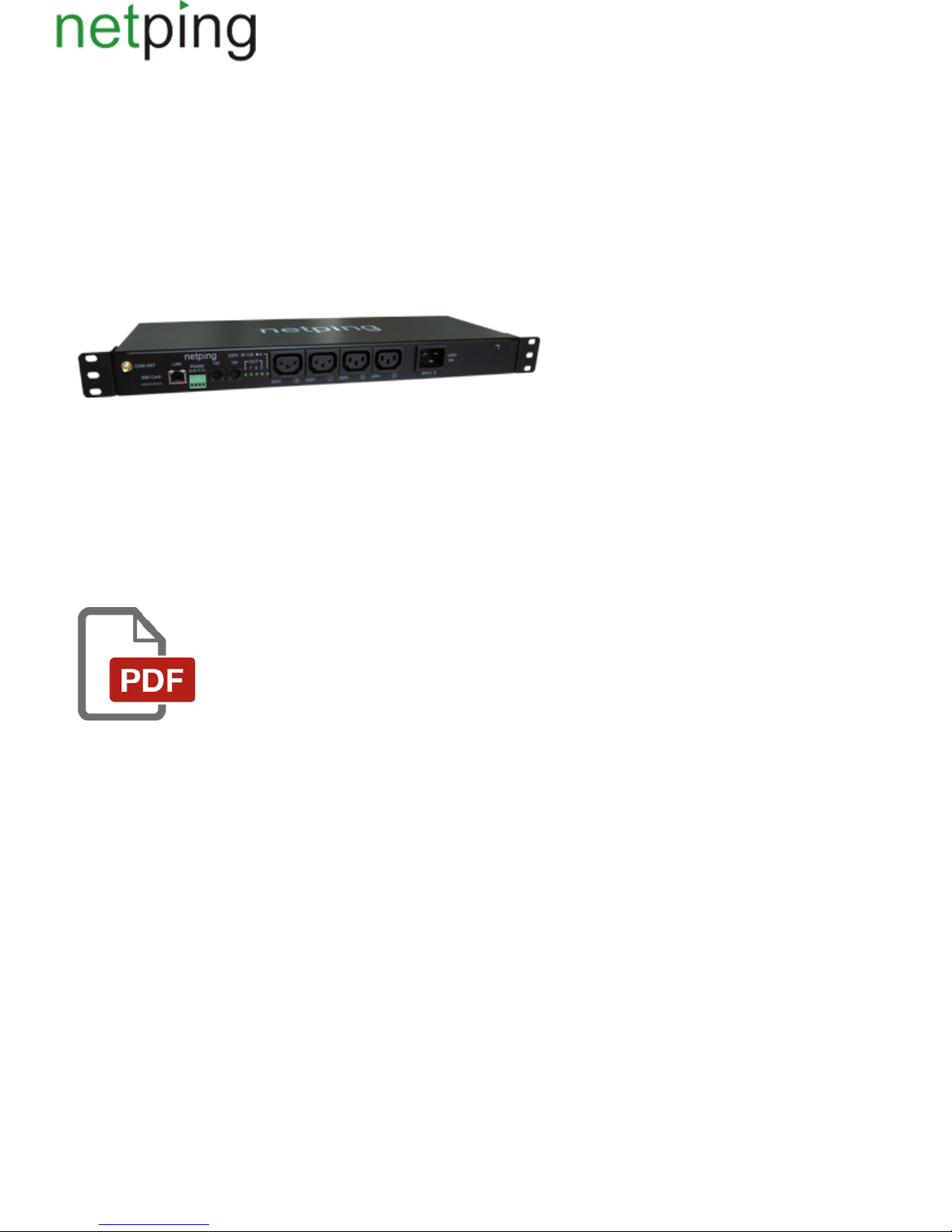
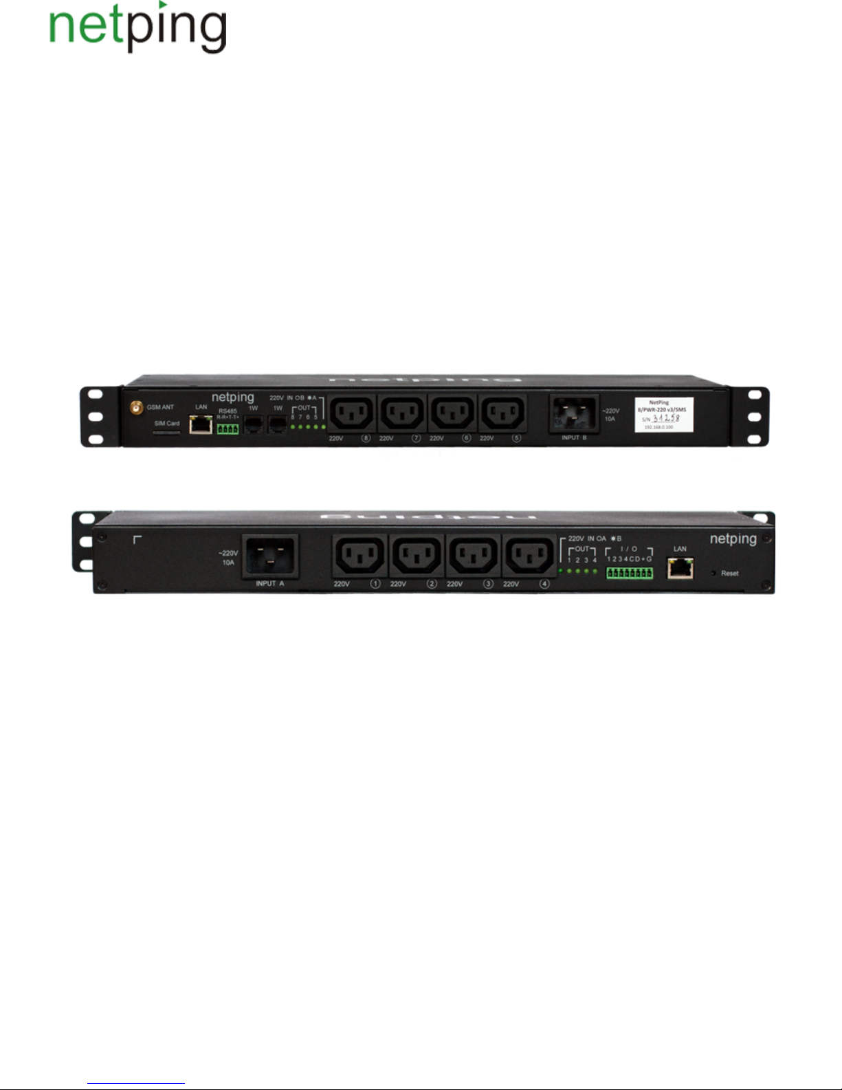
Appearance
A device is designed in standard dimensions for installation in a 19' rack. A height of a device is 1U. Inputs and output power supply channels are on a
front and back panels of a device. Fasteners for mounting in a rack ("ears") can be bolted toNetPing 8/PWRv3/SMS both front and back, which gives a
possibility to mount a device in a rack by any side. An appearance of device is shown on the pictures.
Front panel:
Back panel:
Copyright © NetPing east Co., Ltd E-mail: Phone:+886-2-23121582[email protected]
[8PWR] Sockets and Indication Elements
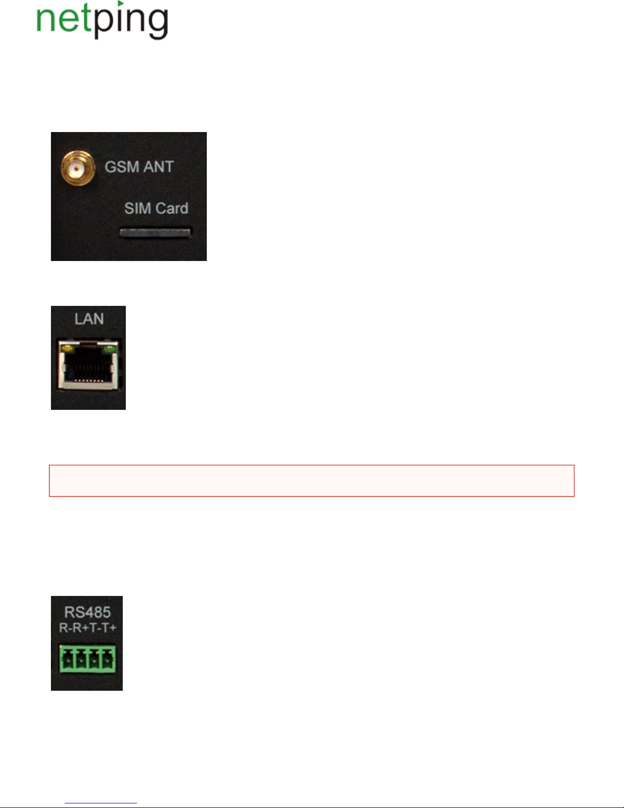
GSM Slots
There are sockets on a front panel on the left to connect an external antenna and a slot to install a SIM card.GSMANT SIMCard
LAN Sockets
Ethernet 10/100 BASE-T port. A device has two such ports: one on a front panel and another one on a back panel. Together they form a dual port
Ethernet-switch. One port is used for a network connection, another one is used for additional equipment connection (another NetPing device,
administrator's laptop, etc.), which gives an opportunity to avoid installing of an additional switch on a remote site. The ports are equivalent, anyone
can be used for a network connection.
The Ethernet ports have two LEDs. A left one is its glowing means that a device is turned on, its blinking means transferring packages to aCPU,
network. A right one is its lighting means having "link" on this port, its blinking means receiving packages from a network.Link,
RS485 Socket
An RS485 socket is used to connect RS485 devices. An RS485 port can work in one of two modes: either as an RS485– Ethernet interface converter by
a TCP protocol or in an electricity meter CE102 (Energy meter)protocol analysis mode.
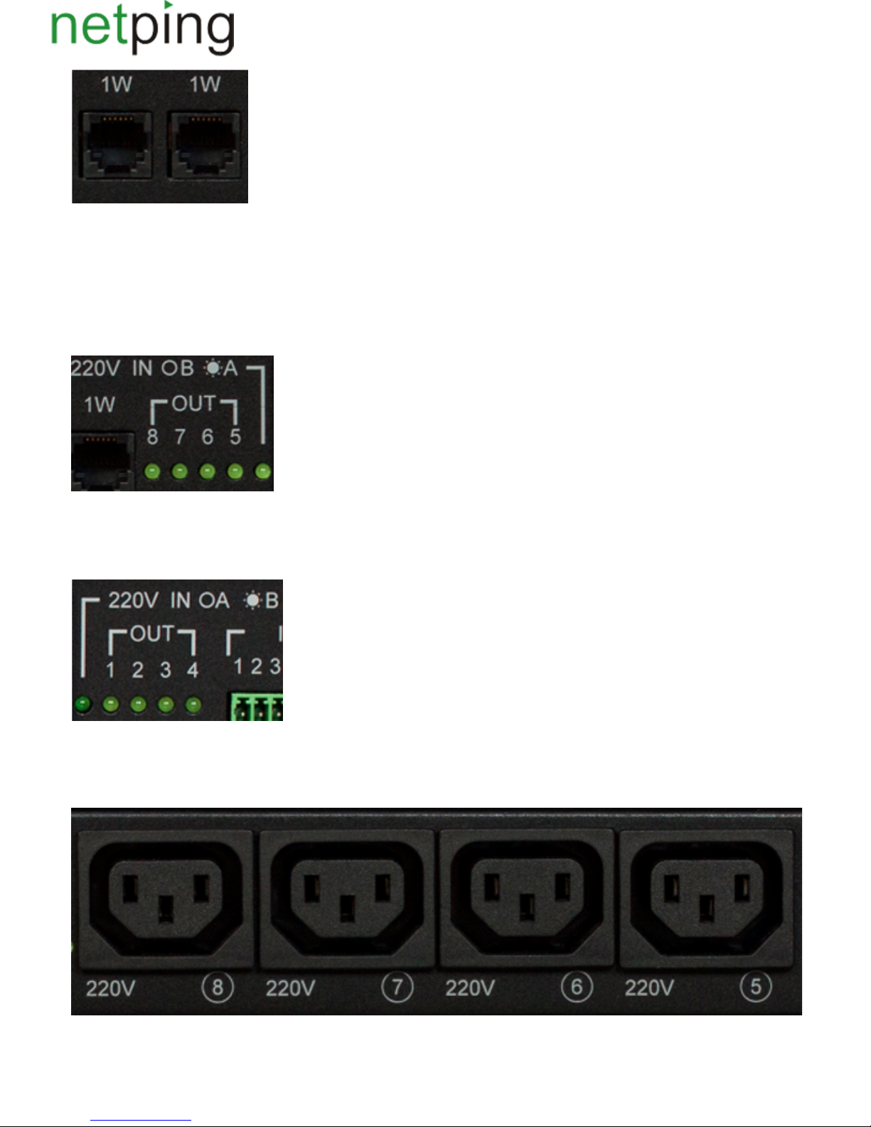
1W Sockets
1W sockets are used to plug sensors of a model line V4, which are built on a 1Wire technology.
Important!Connecting both ports to an Ethernet switch with a disabled STP protocol will cause to creation of a loop in an Ethernet segment.
Copyright © NetPing east Co., Ltd E-mail: Phone:+886-2-23121582[email protected]
Power Supply Channels Status Indication
On a front panel there are LEDs that indicate a status of the second group of power supply channels. Channels 5 - 8 are included into this group. A
status of each channel is represented by a corresponding LED of an group. A LED is glowing when there is a voltage on an output (a relay isOUT
closed).
220vINOB *A LED shows from what input the second group of channels is fed. A LED glows when a power supply is fed from an input A, which is
located on a back panel of a device.
On a back panel there are LEDs that indicate a status of the first group of power supply channels.Channels 1 - 4 are included into this group. A status
of each channel is represented by a corresponding LED of an group. A LED is glowing when there is a voltage on an output (a relay is closed).OUT
220vINOA *B LED shows from what input the first group of channels is fed. A LED glows when a power supply is fed from an inputB, which is
located on a front panel of a device.
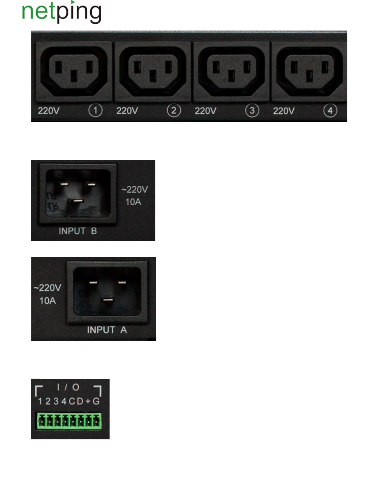
Power Supply Channels
On a front panel there is the second group of power supply channels, with numbers of channels 5 – 8.
On a back panel there is the first group of power supply channels, with numbers of channels 1 -4.
Copyright © NetPing east Co., Ltd E-mail: Phone:+886-2-23121582[email protected]
Power Supply Inputs
On a front panel there is a power supply input B.
On a back panel there is a power supply input A.
Sensor Plugin Terminals
On a back panel there is a terminal block for sensors plugin. Assignment of the terminals is from left to right: IO1, IO2, IO3, IO4, SC, SD, +5V, GND.

Copyright © NetPing east Co., Ltd E-mail: Phone:+886-2-23121582[email protected]
Reset Button
A button is located on a back panel of a device. It is designed to reset settings to default values. To reset settings, press the button with aReset Reset
sharp object and hold it while turning on a device.

Copyright © NetPing east Co., Ltd E-mail: Phone:+886-2-23121582[email protected]
[8PWR] Power Supply Channels Management
Channels Management
A NetPing 8/PWRv3/SMS device has eight independent power supply channels. Each channel is managed by a normally closed relay. A relay and tracks
have a big power capacity reserve, which provides a high resistance of a device to overloading.
Each channel can be turned on or turned off independently from others by a command from a web-interface, by an SNMP command or an
SMS-message. Likewise it is possible to automatically turn on or turn off a power supply channel according to a schedule or using a functionality of a
Watchdog or a Logic. There is a need to remember that when a channel is managed by a functionality of a Watchdog or a Logic, it cannot be turned on
or turned off manually (through a web-interface, SNMP, SMS).
Inputs Reservation
A device supports power supply inputs reservation. With this purpose, outputpower supply channels are divided into two groups, with four channels in
each one. Group 1 – channels 1 - 4, Group 2 – channels 5 - 8. For each group a main input is set (1 or 2). Both groups can use the same input as a main
one.
In cases of failure of a main input, a group of channels can be switched to a backup input - it is optional and is configured in a web-interface of a device.
After recovery of a main input a group of channels returns back to it either automatically or by an administrator's command. This behavior is also
programmed in a web-interface of a device. Switching of a group of output channels from one input to another can be done from a web-interface, by an
SNMP command, SMS-message.
All switches between the inputs occur with a two-second power supply turning off of a group of channels.
Device's software guarantees consequent turning off (and consequent turning on) of output power supply channels while switching from a main input to
a backup one to reduce a value of the switched current.
Connecting a Load to Output Channels
When connecting a load to output power supply channels there is a need to take into account capacity limits of a NetPing 8/PWRv3/SMS device. A
maximum capacity of each channel separately is 1500 Watts. A maximum total capacity of four channels in one group is 1725 Watts. I.e., if a consumer
with a maximum capacity of 1500 Watts is connected to a channel1, then it is possible to connect a total load no more than 225 Watts to channels 2,3,4.
Each input can provide 3500Watts, therefore both groups of power supply channels can be fed from one input (1725Watts + 1725Watts = 3500Watts).
Copyright © NetPing east Co., Ltd E-mail: Phone:+886-2-23121582[email protected]
[8PWR] Sensors Plugin
Sensors of Dry Contact Type
Dry contact sensors are: door opening sensors, buttons and other sensors, which mechanism is in opening/closing a conductor. A sensor is connected
with two wires to an IO line of a device according to the table (an order of plugging wires does not matter).
Sensor Flex Netping 8/PWRv3/SMS Terminal
First wire – 1One of IO lines /2/3/4
Second wire G
A sensor is packaged with an inseparable cable, withconnectors on the ends. A cable length can be increased with the help of flat cable extenders of
sensor, which are sequentially plugged one into another. Or it can be done independently with the help of any wire with a minimum cross sectionRC-4
of 0,4 mm . Maximum allowable length of a flat cable is 100 m.
2
Temperature Sensors
TS- and WT- temperature sensors are plugged in by a four-wire line according to the table.
Sensor Flex Netping 8/PWRv3/SMS Terminal
Labelled wire (red). C
Second wire after a labelled one D
Third wire after a labelled one +
Fourth wire after a labelled one G
It is possible to plug up to 8 temperature sensors to a device – four TS-sensors and four WT-sensors. Sensors are connected in a parallel to the same
terminals.
Leakage Sensors
A leakage sensor is connected by a four-wire line according to the table.
Sensor Flex Netping 8/PWRv3/SMS Terminal
Green. One of IO lines – 1/2/3/4
Yellow (White) G
Red +
Black G
! Important Sensors of a dry contact type, a 220 V occurrence sensor, a leakage sensor and others are plugged to IOlines of a device. You can
plug any four sensors out of this set.
!Important A corresponding IOline should be set to an input mode in settings of a device.
Important! It is prohibited to plug sensors with the same numbers to a device.
Important! Sensors of a dry contact type, a 220 V occurrence sensor, a leakage sensor and others are plugged to IOlines of a device. You can
plug any four sensors out of this set.

Copyright © NetPing east Co., Ltd E-mail: Phone:+886-2-23121582[email protected]
A sensor is packaged with an inseparable cable, withconnectors on the ends. A cable length can be increased with the help of flat cable extenders of
sensor, which are sequentially plugged one into another. Or it can be done independently with the help of any wire with a minimum cross sectionRC-4
of 0,4 mm . Maximum allowable length of a flat cable is 100 m.
2
220V Occurrence Sensors
A 220V occurrence sensor .is pugged by a two-wire line according to the table
Sensor Flex Netping 8/PWRv3/SMS Terminal
Output. Black-and-white wire – 1/2/3/4One of IO lines
Common. Black wire G
A sensor is packaged with an inseparable cable, withconnectors on the ends. A cable length can be increased with the help of flat cable extenders of
sensor, which are sequentially plugged one into another. Or it can be done independently with the help of any wire with a minimum cross sectionRC-4
of 0,4 mm . Maximum allowable length of a flat cable is 100 m.
2
IR Transceiver IRC-TRv2
IR transceiver is plugged by a four-wire line according to the table:
Sensor Flex NetPing 8-PWR-220 v3/SMS Terminal
Labelled wire (red). C
Second wire after a labelled one D
Third wire after a labelled one +
Fourth wire after a labelled one G
Подключениерозеток NetPing AC/DIN
При подключении розетки к устройству задействованы все провода, кроме коричневого. IO линию, к которой подключена розетка AC/DIN,
необходимо перевести в состояние "выход". При состоянии лог. 0 на IO линии 220В будет присутствовать на розетке, нагрузка будет
включена. При состоянии лог. 1 на IO линии розетка будет обесточена, нагрузка выключена.
Шлейф датчика КлеммаNetPing 8-PWR-220 v3/SMS
Красный провод (маркированный) +
Черный провод G
Синий провод Одна из IO линий – 1/2/3/4
Important! A corresponding IOline should be set to an input mode in settings of a device.
Important! Sensors of a dry contact type, a 220 V occurrence sensor, a leakage sensor and others are plugged to IOlines of a device. You can
plug any four sensors out of this set.
Important! A corresponding IOline should be set to an input mode in settings of a device.
Важно! Коричневый провод не используется и должен остаться неподключенным!

Copyright © NetPing east Co., Ltd E-mail: Phone:+886-2-23121582[email protected]
Для коммутации нагрузки в NetPing AC/DIN используется реле с нормально замкнутыми контактами. Это означает, что, если управляющий
провод никуда не подключен, 220В будет присутствовать на розетке и нагрузка будет включена.
A sensor is packaged with an inseparable cable, withconnectors on the ends. A cable length can be increased with the help of flat cable extenders of
sensor, which are sequentially plugged one into another. Or it can be done independently with the help of any wire with a minimum cross sectionRC-4
of 0,4 mm . Maximum allowable length of a flat cable is 100 m.
2

Copyright © NetPing east Co., Ltd E-mail: Phone:+886-2-23121582[email protected]
[8PWR] Setting Parameters to Default Values (to the Factory Settings)
Resetting parameters to the factory settings is necessary in the following cases:
A loss of a login and/or password to a web interface of a device;
A lack of information about current IP address of a device;
In some cases after a device software update.
A procedure of resetting parameters to the factory settings changes all customizable parameters of a device to the default ones. (IP and MAC addresses,
access filters, a user name, a password, etc.).
To reset parameters to default settings, fulfill the next actions sequentially:
Turn off a power supply of a device;
Press the Reset button (a button Set for a Uniping v3 device);
Turn on a power supply of a device, continuing to hold Reset button pressed for 15-20 seconds;
Release the button. All parameters of a device are set to default settings.
After resetting parameters to default settings there is a need to do an initial configuration of a device.
On default, the next parameters of a device are set:
User name: visor
Password: ping
IP address: 192.168.0.100
Subnetwork mask: 255.255.255.0
Gateway: not set
SNMPcommunity: SWITCH
MAC-address: 00 a2 xx xx xx xx
Here xx xx xx xx corresponds to a serial number of a device. Thus, all devices after being manufactured have unique MAC-addresses.

Copyright © NetPing east Co., Ltd E-mail: Phone:+886-2-23121582[email protected]
[8PWR] Using IO Lines for External Devices Management (in an Output Mode)
Input-Output lines of a device can be used for an input work as well as in an output mode for managing external devices.(IO)
A device has four IO lines, corresponding to contacts I1 –I4 of a terminal block. Lines configuration for work as an input or an output is made through
a controlling web-interface of a device. All four IO lines can be customized independently.
Lines management can be done by SNMP commands, via a web-interface or by SMS-commands, sent to a device.
Such device functions as a watchdog and a scheduled load management are NOT AVAILABLE for IO in an output mode.
Examples of using:
Remote servers reboot – an imitation of pressing “reset”;
Remote management of an alarm, a light, a fan;
Management of an electric lock, electric gates on a remote object;
Management of smart home elements - watering flowers, opening-closing louvers, water pump, heating boiler, heaters, etc. Remote
management of a power installation (diesel generator, gasoline).
Electric specifications of a line in an output mode:
High level (logic «1») – 5 V voltage, 1,5 mA current.
Low level (logic «0») - 0 V voltage, up to 150 mA current.
It is acceptable to use intermediate relays with a power supply voltage 12 V from an external source.
A ready socket can be used for IO lines connection NetPing AC/DIN socket
In addition, we can advise ready assembly relays of other manufacturers, which can be connected to our devices:
http://www.masterkit.ru/shop/smarthome/executive-devices/1327359 - a power module switch (4 independent channels, 2 kWt 10A each)MP701
http://www.masterkit.ru/shop/smarthome/executive-devices/1326291 - a load switching relay up to 6A 12V
http://www.masterkit.ru/shop/smarthome/executive-devices/1494003 - a power module on a basis of a powerful relay with an optocoupler forMP220
managing a load up to 4 kWt (20A).
Therefore, when using IO lines in an output mode, it is possible to independently manage four external devices.
For more detailed information, please contact a technical support[email protected]
Important! A correct electrical coordination of IO lines is required when connecting external executive
devices.
Important! IO lines do not have a galvanic isolation with a device! Remember about electrical safety when
using relays that commutate 220 V circuits. All work must be done by specialists with a correspondent
qualification who have a permit to work with such a voltage!

Copyright © NetPing east Co., Ltd E-mail: Phone:+886-2-23121582[email protected]
[8PWR] Shipping Kit
A shipping kit is shown at the picture:
A shipping kit includes:
A device NetPing 8/PWRv3/SMS;
An antenna;
A user guide;
A packing box;
A power cord – 2 pcs.;
Mating terminals – 2 pcs.

Copyright © NetPing east Co., Ltd E-mail: Phone:+886-2-23121582[email protected]
[8PWR] Operating and Storage Conditions
A device is designed for continuous round the clock operation indoors. In operating conditions of use, a device is resistant to an environment with
temperature in a range of 0°С - +40°С (32 – 104 degrees Fahrenheit) and relative humidity in a range of 5% - 95 % at 25°С (77 degrees Fahrenheit)
without moisture condensation. A device should be protected from direct moisture and direct sun light.
A construction of a device provides a reliable uninterrupted work during a long period of time without maintenance.Highly developed functionality of
remote setting and configuration of a device allows changing any parameters remotely and centrally for the most of the devices.
Devices should be stored in a temperature range between - 40°С and +70°С.
In rooms for keeping a device, a content of dust, acid and alkali gases, aggressive gases and other harmful impurities causing corrosion, should not
exceed a content of corrosion-active agents for atmosphere of type 1.
Important! A device must be connected to a power supply socket with a grounding contact or a hole, where a contact, located at an outlet
and connected to a ground wire, is inserted. Grounding must be performed according to the State Standard Р 50571.21-2000. An infraction
of this rule is aviolation of a device operation conditions and may be dangerous to human lives as well as damage other devices!

Copyright © NetPing east Co., Ltd E-mail: Phone:+886-2-23121582[email protected]
[8PWR] Warranty
The manufacturer guarantees normal operating of the product within 24 months from the date specified on the warranty sticker if a buyer follows
operating and storage conditions. Manufacturer warranty applies only to failure of a device, which occurred because of defects in manufacturing
process of products and components used. If during a warranty period, the manufacturer receives a notice of such defects, it will repair or exchange a
product (by its own discretion). If the manufacturer is unable to repair or replace a flawed item during a period of time determined by the current
legislation, the manufacturer according to a customer’s wish can return the amount paid for the product at the time of purchase. The manufacturer
provides a limited warranty on firmware and device configuration software. In case of detecting any errors in software, which became known to the
manufacturer on its own or from a customer, the manufacturer will fix these errors within a reasonable time and provide an update for the
customer.Only the errors that block normal use of the device at conditions and for performing functions, described in this User Guide, are subject to
mandatory fix.This warranty does not apply to cases, when defects appear because of: a misuse of a device, any modifications of a device without a
written permission of the manufacturer, opening up a device, except cases, foreseen by this description, repairing by unauthorized personnel, using or
storing a device out of the range of allowable temperature and humidity, pressure, a software modification, and the reasons, listed below:
A device failed because of the problems in a public electric network, plugging a device into power supply networks with invalid parameters,
absence of grounding, etc. (power fluctuations and surges, overloading, etc.);
A device failed because of a liquid inside;
A device failed as a result of extreme temperatures;
A device failed because of mechanical damage;
A device failed because of connecting a power supply unit with invalid output voltage or a defective power supply unit;
There are foreign objects, insects, etc inside the enclosure;
During operation, a voltage bigger than an allowable voltage range by the Ethernet standard has been supplied to the ports of a device.
Table of contents
Other NetPing Power Distribution Unit manuals


