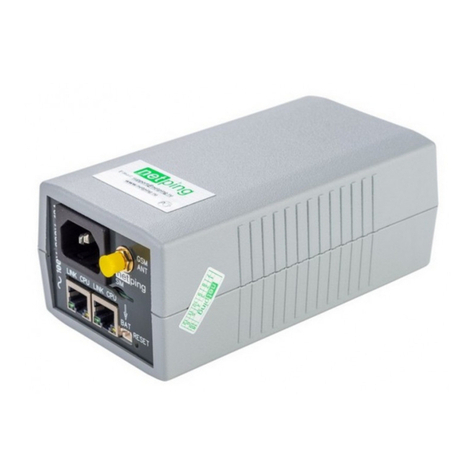
NetPing NP-SM4 User manual

[ENG] NetPing NP-SM4, User guide

[ENG] NetPing NP-SM4, User guide -
2
Содержание
[SM4] Introduction ...................................................................................................... 4
[SM4] NP-SM4 Switch Overview ................................................................................. 5
A Purpose of a Device......................................................................................................................... 5
Appearance ........................................................................................................................................ 5
Sockets and LEDs ............................................................................................................................... 5
Power Supply Unit ............................................................................................................................. 5
[SM4] Shipping Kit....................................................................................................... 7
[SM4] Installation and Connection............................................................................. 8
[SM4] PoE Technology in NP-SM4 Switches .............................................................. 9
[SM4] QoS Technology in NP-SM4 Switches............................................................ 12
[SM4] Warranty.......................................................................................................... 13

[ENG] NetPing NP-SM4, User guide -
–

[ENG] NetPing NP-SM4, User guide -[SM4] Introduction
[SM4] Introduction
–
•
•
•
[SM4] Introduction
This User Guide helps to know the peculiarities of a device operation as well as to get an idea about its functionality
and technical specifications, and prepare a device for operation. A User Guide describes a model NP-SM4 of
switches (hereinafter a switch or a device).
A User Guide is designed for network administrators and users, who set up or operate a device. To work with a
device properly, a user must have an idea about the principles of building and functioning of local networks as well
as possess the next knowledge and skills:
Basic knowledge in the area of local and global networks;
Basicknowledgeintheareaofarchitectureandprinciples of work of TCP/IP networks;
Basic knowledge in the area of architecture and principles of work of Ethernet networks.

[ENG] NetPing NP-SM4, User guide -[SM4] NP-SM4 Switch Overview
[SM4] NP-SM4 Switch Overview
–
[SM4] NP-SM4 Switch Overview
In this section a using area of a device is described as well as its appearance, sockets and indication elements.
A Purpose of a Device
NP-SM4 – is an uncontrollable switch with 4 ports. A peculiarity of this switch is its power supply feeding from PoE
(IEEE 802.3.at or IEEE 802.3.af) with a possibility to further transmit a PoE power supply. This helps to connect NP-
SM4 switches in a circuit, using only an Ethernet cable.
NP-SM4 allows connecting a necessary amount of workplaces, VoIP phones, video camerasto the Ethernet with a
minimal expense on a cable infrastructure.
A switch is made in a body of a wall computer socket, which makes it convenient to assemble on a horizontal or a
vertical surface.
Appearance
An appearance of a switch is represented on a picture below:
Sockets and LEDs
A switch has 4 Ethernet ports 10/100BASE-TX. Two of them are on a front panel of a device, and the rest two ones
are on left and right side panels. There is a socket for connecting an external power supply unit (not included into a
shipping kit) on a back panel. There is a LED indicating a power supply availability on a top panel of a device.
Front Panel Back Panel
Left Panel Right Panel
Power Supply Unit
A device is shipped without a power supply unit included. A device can be fed from a POE Ethernet network or it is
possible to plug an external power supply unit to a device with a voltage from 12V to 48V and a capacity not less
than 5Watts (to feed a switch itself nonmeteringPOE consumers!).
If a device should operate as a POE injector for other devices in a network supporting an IEEE 802.3af/at
standard, it is necessary to use a power supply unit with a voltage 48V!A capacity of a power supply unit must
be enough to provide a total consumed capacity of a switch itself and all connected POE consumers.

[ENG] NetPing NP-SM4, User guide -[SM4] NP-SM4 Switch Overview
[SM4] NP-SM4 Switch Overview
–
To plug an external power supply unit, a socket DJK-02A with a 2.1 mm dowel is used.
It is recommended to use Power Supply Unit 48V 1.5Aas an external power supply unit of a switch.

[ENG] NetPing NP-SM4, User guide -[SM4] Shipping Kit
[SM4] Shipping Kit
–
•
•
•
[SM4] Shipping Kit
A shipping kit includes:
a NP-SM4 switch;
6 mini jumpers for PoE switching;
a ZIP pack.
A power supply unit is not included into a shipping kit!

[ENG] NetPing NP-SM4, User guide -[SM4] Installation and Connection
[SM4] Installation and Connection
–
•
•
•
•
•
•
[SM4] Installation and Connection
Forasuccessfulinstallationofaswitch, thereisaneedtofulfillthefollowing:
Define, how the switch will be supplied: from an power supply unit or by PoE;
Define, whichportsoftheswitchwillprovideapowersupplybyPoE technologytootherdevices;
Important! A board of a switch is under 48 V voltage, which is dangerous for your life. To avoid an electric shock,
always turn off a power supply of a switch before removing its lid. A switch operation with an opened lid is not
allowed.
Install jumpers to transmit a power supply (Look at the Section “PoE Technology in NP-SM4 Switches”));
Put a switch in a place of planned installation;
Apply power to a switch. A LED will light up on a case of a device;
Connect patch cords to a switch.

[ENG] NetPing NP-SM4, User guide -[SM4] PoE Technology in NP-SM4 Switches
[SM4] PoE Technology in NP-SM4 Switches
–
[SM4] PoE Technology in NP-SM4 Switches
A switch Netping NP-SM4 has four ports: P0, P1, P2, P3. Their location and numeration are shown at the picture 6.
Picture 6. Ports Location
A port P3 is designed to feed a power supply to a switch NP-SM4 with the help of PoE-injector or any other PSE
device. A power supply voltage range at a port P3 is 42 – 60V. A compatibility determination sheme works at a port
P3 with PoE devices of af/at standard. Jumper J6 disables a work of PoE determination scheme and decreases a
lower limit of a voltage range to 5 V (more detailed information about J6 is given below).
A switch can be fed with the help of external power supply unit. An input voltage range for a supply unit is 11 – 60 V.
A priority is given to a power supply unit. When a voltage on input of a power supply unit exceeds10 V, PoE input is
disabled.
NP-SM4 switch can transmit power supply received from PoE-injector or a power supply unit on ports P0, P1, P2.
Important! A partner PoE determination scheme doesn't work on ports P0,P1,P2. When jumpers are installed,
power supply is always fed without determining if a partner supports PoE. Power supply is always fed on both pairs
for transmitting data and on unused pairs.(Аand Вvariants of PoE standard). It's impossible to choose either one
of the variants.
By default, NP-SM4 switch does not feed the ports P0, P1, P2. There is a need to install jumpers on a board of a
switch to feed one or several ports. Two jumpers are responsible for each port. A location of jumpers is shown at the
picture 7.

[ENG] NetPing NP-SM4, User guide -[SM4] PoE Technology in NP-SM4 Switches
[SM4] PoE Technology in NP-SM4 Switches
–
•
•
•
Picture 7. Location of Jumpers on a Board of a Switch
J4 jumpers block is responsible for feeding. Two upper jumpers (when installed) enable P1 port feeding, two middle
ones enable P2 port feeding, and two lower ones enable P0 port feeding.
J6 jumper (when installed) decreases a lower limit of a voltage range of P3 port to 5 V (when J6 is not installed, a
voltage on P3 should be in a range 42 – 60 V). This helps to feed a device even with a long cable with a big voltage
drop. Installing of a jumper J6 disables a function of auto determination, which is used by PSE devices to determine
a presence of PoE consumers (PD devices). Thus PSE devices will feed NP-SM4, which has a jumper J6 installed. J6
jumper is not included into a shipping kit.
Jumpers are installed horizontally. Improper installation of jumpers can damage a switch. An example of a proper
installation of jumpers for feeding P2 port is shown at the picture 8.
Picture 8. Proper Installation of Jumpers
Important! A board of switch is under 48 V voltage, which is dangerous for a life. To avoid an electric shock, always
turn off a power supply of a switch before removing its lid.A switch operation with an opened lid is not allowed.
Important! Do not turn on feeding of ports, where an equipment, which does not support PoE, can be connected.
To feed a certain port of a switch, it is a necessary to fulfill the following:
Turn off power supply of NP-SM4 switch;
Remove a lid of a switch, using an end screwdriver. To do this, there are grooves near P3 and P2 ports;
Install/remove jumpers;

[ENG] NetPing NP-SM4, User guide -[SM4] PoE Technology in NP-SM4 Switches
[SM4] PoE Technology in NP-SM4 Switches
–
•
•
Close a lid of a switch;
Turn on power supply of a switch.
A maximum capacity of a NP-SM4 switch (and all PoE consumers, connected to it), should not exceed 30 watts
according to the 802.3at standard. Consumers can be connected to different ports of NP-SM4 switch or to one port,
there is no limit to a total power. A maximum power consumption of NP-SM4 switch itself is 2.5 watts, which gives
an oppurtunity to join up to 10 NP-SM4switches in a circuit, using short patch cords. However, it is not
recommended to join more than four switches in a circuit.
There is a need to take into account a voltage dropon long lines, as for 100 meter cable segment of class 5 a voltage
drop can make up to 10 V on a device. Thus it is possible to join only two devices in a circuit.

[ENG] NetPing NP-SM4, User guide -[SM4] QoS Technology in NP-SM4 Switches
[SM4] QoS Technology in NP-SM4 Switches
–
[SM4] QoS Technology in NP-SM4 Switches
QoS technology in NP-SM4 switches is programmed to provide a good result for the most scenarios with default
settings.
Amount of queues in the interface:4
Queues servicing mechanism:WRR (Weighted Round Robin)
Traffic classification: by six high-order IP TOS and IPv6 TCbits
Classification table:
Queque number Beginning of the Range End of the Range
00x00 0x0f
10x10 0x1f
20x20 0x2f
30x30 0x3f
Queque 3 has the biggest weight, queque 0 – the least one.
Make sure that IP-phones mark voice traffic with DSCP values, which correspond to queques 2 or 3 to ensure a
prioritization of a voice traffic.

[ENG] NetPing NP-SM4, User guide -[SM4] Warranty
[SM4] Warranty
–
•
•
•
•
•
•
•
[SM4] Warranty
The manufacturer guarantees normal operation of the product within 24 months from the date specified on the
warranty sticker if a buyer follows operating and storage conditions. Manufacturer warranty applies only to failure
of a device which occurred because of defects in manufacturing process of products and components used. If
during a warranty period the manufacturer receives a notice of such defects, it will repair or exchange the product
(by its own discretion). If the manufacturer is unable to repair or replace a flawed item during a period of time
determined by the current legislation, the manufacturer according to a customer’s wish can return the amount paid
for the product at the time of purchase. The manufacturer provides a limited warranty on firmware and device
configuration software. In case of detecting any errors in the software which became known to the manufacturer on
its own or from a customer, the manufacturer will fix these errors within a reasonable time and provide an update
for the customer. Only the errors that block normal use of the device at conditions and for performing functions
described in this User Guide are a subject to mandatory fix. This warranty does not apply to cases when defects
appear because of: a misuse of a device, any modifications of a device without a written permission of the
manufacturer, opening up a device (a warranty sticker on the case of a device is damaged)except cases foreseen by
this description; repairing by unauthorized personnel, using or storing a device out of the range of allowable
temperature and humidity, pressure, a software modification, and the reasons, listed below:
A device failed because of the problems in a public electric network, plugging a device into power supply
networks with invalid parameters, absence of grounding, etc. (power fluctuations and surges, overloading,
etc.);
A device failed because of having liquid inside;
A device failed as a result of extreme temperatures;
A device failed because of mechanical damage;
A device failed because of connecting a power supply unit with invalid output voltage or a defective power
supply unit;
There are foreign objects, insects, etc inside the enclosure;
During operation a voltage bigger than an allowable voltage range by the Ethernet standard has been
supplied to the ports of a device.
Table of contents
Other NetPing Power Distribution Unit manuals
Popular Power Distribution Unit manuals by other brands
Wiremold
Wiremold Power Commander installation instructions

Panduit
Panduit smartzone G5 user manual
Siemens
Siemens SIVACON 8PS installation instructions
LifeSafety Power
LifeSafety Power FlexPower A8 installation manual

environmental potentials
environmental potentials EP-2000 Series Installation and maintenance manual
ATEN
ATEN eco PDU PE Series user manual
