NetPing 2 IP PDU ETH 53R14 User manual

[ENG] NetPing 2 IP PDU ETH 53R14 & NetPing 2 IP
PDU GSM3G 203R15, User guide

[ENG] NetPing 2 IP PDU ETH 53R14 & NetPing 2 IP PDU GSM3G 203R15, User guide -
2
Содержание
[ENG][2PWR] Introduction.......................................................................................... 5
[ENG][2PWR] Disclaimer and Copyright..................................................................... 6
[ENG][2PWR] Shipping Kit for The Device.................................................................. 7
[ENG][2PWR] Overview and Key Features.................................................................. 8
Appearance ........................................................................................................................................ 8
Device Specifications....................................................................................................................... 10
[ENG][2PWR] Features of Local Controls, LEDs, and Sockets on a Case of the
Device ........................................................................................................................ 12
Front View......................................................................................................................................... 12
Back View.......................................................................................................................................... 14
[ENG][2PWR] Connection, Installion, and Initial Configuration of the Device....... 16
Step 1................................................................................................................................................ 16
Step 2................................................................................................................................................ 16
Step 3................................................................................................................................................ 17
Step 4................................................................................................................................................ 18
Step 5................................................................................................................................................ 19
Step 6................................................................................................................................................ 20
[ENG][2PWR] Autonomous operation...................................................................... 22
[ENG][2PWR] Connecting External Sensors and Accessories ................................. 23
The description of contacts............................................................................................................. 23
i2C Connecting sensors and devices to the i2C bus ....................................................................... 24
Sensors of the "Dry contact" type................................................................................................... 27
Two wire sensors.............................................................................................................................................................. 27
Liquid sensor (mod.2605) ................................................................................................................................................ 27
PIR DETECTOR (mod.M105-1E)........................................................................................................................................ 28
Actuation Devices............................................................................................................................. 29
Buzzer (mod.STD-3025) ................................................................................................................................................... 29
NetPing AC/DIN socket .................................................................................................................................................... 30

[ENG] NetPing 2 IP PDU ETH 53R14 & NetPing 2 IP PDU GSM3G 203R15, User guide -
3
[ENG][2PWR] Using IO Lines in the «Output» Mode for Controlling External
Devices....................................................................................................................... 32
Electric Parameters of IO Lines ....................................................................................................... 32
[ENG][2PWR] Resetting Parameters to Default Values............................................ 34
[ENG][2PWR] Operating, Storage, Transportation and Disposal Information....... 36
[ENG][2PWR] Safety Precautions ............................................................................. 37
[ENG][2PWR] Firmware Update................................................................................ 38
[ENG][2PWR] Warranty.............................................................................................. 39
[ENG][2PWR] Where to Get the Document with the Firmware Description? ......... 40
[ENG][2PWR] What to Do if There Are Still Some Questions? ................................. 41

[ENG] NetPing 2 IP PDU ETH 53R14 & NetPing 2 IP PDU GSM3G 203R15, User guide -
–

[ENG] NetPing 2 IP PDU ETH 53R14 & NetPing 2 IP PDU GSM3G 203R15, User guide -[ENG][2PWR] Introduction
[ENG][2PWR] Introduction
–
•
•
•
[ENG][2PWR] Introduction
The document containsa description of preparing devices for remotepower supply control (IP PDU) NetPing 2 IP
PDU ETH 53R14andNetPing 2 IP PDU GSM3G 203R15for operation, external electric interfaces, and peculiarities of
the usage.
A User Guide is designed for network administrators and users, who set up or operate a device. To work with a
device properly, a user must have an idea about the principles of building and functioning of local networks as well
as possess the next knowledge and skills:
Basic knowledge in the area of local and global networks;
Basicknowledgeintheareaofarchitectureandprinciples of work of TCP/IP networks;
Basic knowledge in the area of architecture and principles of work of Ethernet networks.

[ENG] NetPing 2 IP PDU ETH 53R14 & NetPing 2 IP PDU GSM3G 203R15, User guide -[ENG][2PWR] Disclaimer and Copyright
[ENG][2PWR] Disclaimer and Copyright
–
[ENG][2PWR] Disclaimer and Copyright
The information, contained in this document, can be changed by a manufacturer without a prior notice.Although
every effort was made to make the information in this document accurate and without errors, a manufacturer is not
liable for their possible presence and for the consequences that may result from the errors herein. A manufacturer is
not liable if supplied equipment, software and this user guide does not correspond to expectations of a user and
his/her opinion about where and how to use all the above.All copyrights on supplied devices, described in this User
Guide, as well as firmware and software of devices and this User Guide belong to NetPing global Ltd. Сopying,
replication and translation of this user guide to other languagesare not allowed without a prior written permission
of a rightholder. Copying, replication, changing, disassembling of provided software are not allowed without a prior
written permission of a rightholder. For the part of software that is provided in source codes, there is a separate
license agreement, which defines an order of its use and modification. Other trademarks used in this description
belong to corresponding rightholders.
Developer and manufacturer:
NetPing east Co Ltd.

[ENG] NetPing 2 IP PDU ETH 53R14 & NetPing 2 IP PDU GSM3G 203R15, User guide -[ENG][2PWR] Shipping Kit for The Device
[ENG][2PWR] Shipping Kit for The Device
–
•
•
•
•
•
•
•
[ENG][2PWR] Shipping Kit for The Device
This shipping kit includes:
NetPing 2 IP PDU ETH 53R14orNetPing 2 IP PDU GSM3G 203R15 - 1 pc.;
mate terminal block STK-15EDGK-3.5-8P - 1 pc.;
power cord- 1 pc.;
GSM antenna (for the version of the modelNetPing 2 IP PDU GSM3G 203R15) - 1 pc.;
screwdriver- 1 pc.;
quick start guide - 1 pc.;
package cardboard box - 1 pc.

[ENG] NetPing 2 IP PDU ETH 53R14 & NetPing 2 IP PDU GSM3G 203R15, User guide -[ENG][2PWR] Overview and Key Features
[ENG][2PWR] Overview and Key Features
–
[ENG][2PWR] Overview and Key Features
It is possible to connect up to two power consumers of the total capacity of 1500W to a device using controlled
electric outlets. To be protected from a short circuit in load and/orexceeding the maximum permissible power, the
device is equipped with an automatic built-inresettable fuse. Spreading the load capacity between the two
channels is random. The load connected to the device is controlled using the own web interface, SNMP protocol,
using HTTP API and by SMS (for a NetPing 2 IP PDU GSM3G 203R15 device with a built-in GSM modem). The device
has a feature of a «watchdog» that allows to reboot connected equipment automatically if it freezes or according to
a previously specified schedule. Electric load of each of the two channelsis controlled independently from each
other, at the same time, individual settings are possible for any of these channels.
Appearance
General appearance. A photo represents a modelNetPing 2 IP PDU GSM3G 203R15
Front view

[ENG] NetPing 2 IP PDU ETH 53R14 & NetPing 2 IP PDU GSM3G 203R15, User guide -[ENG][2PWR] Overview and Key Features
[ENG][2PWR] Overview and Key Features
–
Back view

[ENG] NetPing 2 IP PDU ETH 53R14 & NetPing 2 IP PDU GSM3G 203R15, User guide -[ENG][2PWR] Overview and Key Features
[ENG][2PWR] Overview and Key Features
–
Device Specifications
Device Specifications Value
Switched load power up to 1,5 kW (in total for both channels with the random
distribution between the channels)
Device power consumption 8.5 W
Supply voltage frequency 100..250В50/60 Hz
Temperature range -30С°..+50С° (non-condensing, normal humidity).
Device dimensions 145 x 78 x 57
Packaging dimensions 225 x 93 x 82

[ENG] NetPing 2 IP PDU ETH 53R14 & NetPing 2 IP PDU GSM3G 203R15, User guide -[ENG][2PWR] Overview and Key Features
[ENG][2PWR] Overview and Key Features
–
Device Specifications Value
Weight 357 g.
[ENG] NetPing 2 IP PDU ETH 53R14 & NetPing 2 IP PDU GSM3G 203R15, User guide -[ENG][2PWR] Features of Local Controls,
LEDs, and Sockets on a Case of the Device
[ENG][2PWR] Features of Local Controls, LEDs, and Sockets on a Case of the Device
–
[ENG][2PWR] Features of Local Controls, LEDs, and Sockets on a
Case of the Device
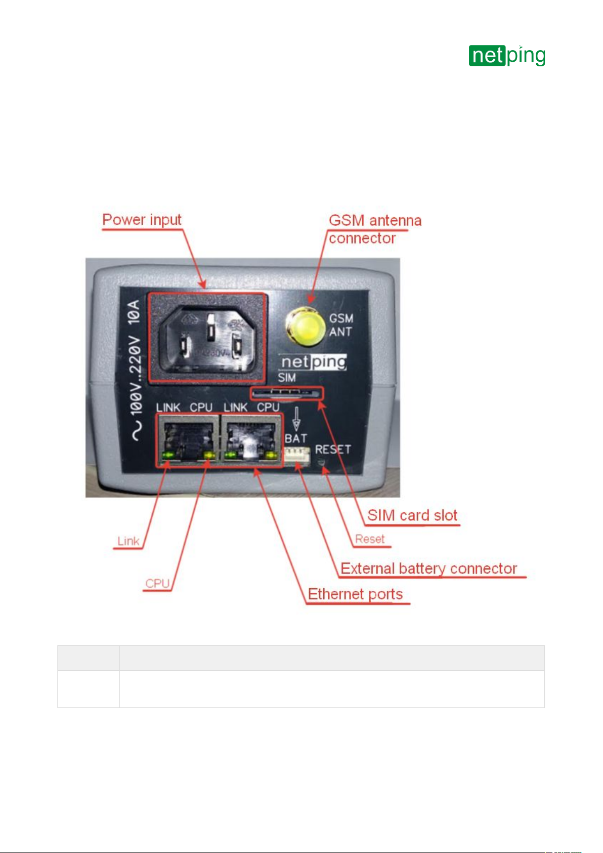
Front View
Element Description
Power
Input
A socket for connecting the device to the power grid.100..250В50/60 Hz

[ENG] NetPing 2 IP PDU ETH 53R14 & NetPing 2 IP PDU GSM3G 203R15, User guide -[ENG][2PWR] Features of Local Controls,
LEDs, and Sockets on a Case of the Device
[ENG][2PWR] Features of Local Controls, LEDs, and Sockets on a Case of the Device
–
•
•
•
•
•
•
•
Element Description
GSM
antenna
connector
A socket for connecting an external GSM antenna. SMA with a connector. It is included only in the
modelNetPing 2 IP PDU GSM3G 203R15, with a built-in GSM modem.
Link Ethernet LED.
Glows if there is a link;
Blinks when receiving packages.
CPU Operation LED.
Glows continuously if a device is powered on;
Blinks 5-6 times when a device is switched on (while a microprogram is loading);
Blinks 15-20 times when resetting parameters of a device to default parameters;
Blinks sometimes when a device sends packages to the Ethernet;
Blinks intensely when shows a firmware update mode.
SIM card
slot
A slot to insert a SIM card of the format Mini-SIM. It is included only to the model NetPing 2 IP PDU
GSM3G 203R15, that has a built-in GSM modem.
Reset A Reset button to reset a device to default parameters (it is done when the Reset button is pressed
while a device is powered on). The external battery module should be switched off.
External
battery
connector
A connector for NetPing external battery module 85m2.
Ethernet
ports
2x10/100 BASE-TX, 2 ports are an uncontrolled switch of the 2nd level, and the third port of a
switch is connected to the CPU of the device.
[ENG] NetPing 2 IP PDU ETH 53R14 & NetPing 2 IP PDU GSM3G 203R15, User guide -[ENG][2PWR] Features of Local Controls,
LEDs, and Sockets on a Case of the Device
[ENG][2PWR] Features of Local Controls, LEDs, and Sockets on a Case of the Device
–
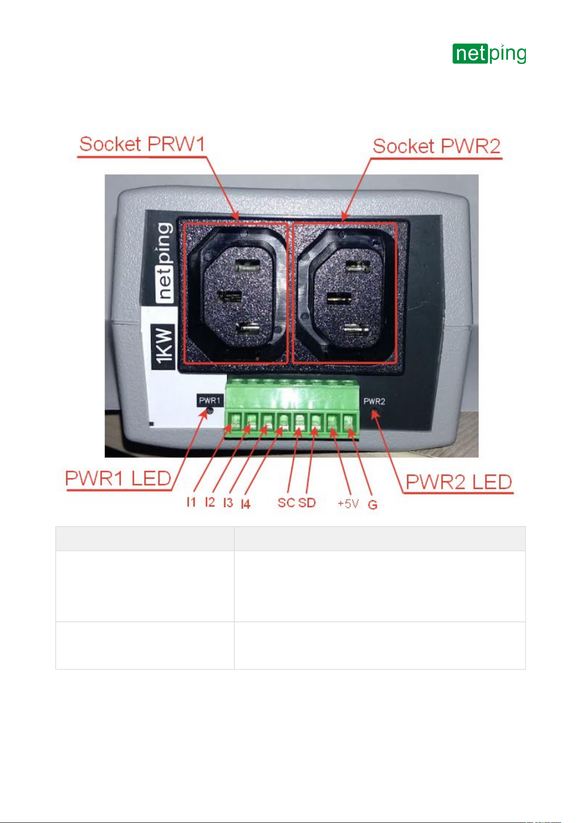
Back View
Element Description
SocketPWR1 and Socket PWR2 Output sockets for remote control (switching on/off, rebooting) the
load.
Switched load power is up to 1,5 kW (in total, for both channels with
a random distribution between the channels).
PWR1 LED and PWR2 LED Socket LEDs. Glowing when switched on (there is the voltage at the
output), not glowing when switched off (there is no voltage at the
output).

[ENG] NetPing 2 IP PDU ETH 53R14 & NetPing 2 IP PDU GSM3G 203R15, User guide -[ENG][2PWR] Features of Local Controls,
LEDs, and Sockets on a Case of the Device
[ENG][2PWR] Features of Local Controls, LEDs, and Sockets on a Case of the Device
–
•
•
•
•
Element Description
I1-I4 IO lines for connecting external sensors of "dry contact" and
controlling running devices.
Specification of the line in the "input" mode:
the voltage of the logic «1»: > 8,2 V;
the voltage of the logic «0»: < 3,5 V.
Line specification in the "output" mode:
the voltage of the logic «1»:push-pull 12V, up to 200mA;
the voltage of the logic «0»: 0V, до 200mA.
SC/SD A bus for connecting the i2C sensors
+5B Power voltage for external sensors or running devices. An
acceptable range is 5..5,3V and output current is 250mA
G Common

[ENG] NetPing 2 IP PDU ETH 53R14 & NetPing 2 IP PDU GSM3G 203R15, User guide -[ENG][2PWR] Connection, Installion, and
Initial Configuration of the Device
[ENG][2PWR] Connection, Installion, and Initial Configuration of the Device
–
[ENG][2PWR] Connection, Installion, and Initial Configuration of
the Device
Step 1
Unpack the device and install it on a horizontal surface.
Step 2
Plug a GSM antenna to the device and locate it in the area of the strong signal of a cell operator. The signal strength
can be controlled using a cell phone according to the number of segments of the signal indicator on the display.
The page shows the photos of the device NetPing 2 IP PDU GSM3G 203R15in the text.
For the modelNetPing 2 IP PDU GSM3G 203R15, with a built-in GSM modem.

[ENG] NetPing 2 IP PDU ETH 53R14 & NetPing 2 IP PDU GSM3G 203R15, User guide -[ENG][2PWR] Connection, Installion, and
Initial Configuration of the Device
[ENG][2PWR] Connection, Installion, and Initial Configuration of the Device
–
Step 3
Insert a SIM card in a corresponding slot at the front panel of a device until you can hear a click. Pay attention to
turning a SIM card contacts down and a cut-off corner into a device.
For the modelNetPing 2 IP PDU GSM3G 203R15, with a built-in GSM modem
A SIM card should be inserted only in the device that is powered off.

[ENG] NetPing 2 IP PDU ETH 53R14 & NetPing 2 IP PDU GSM3G 203R15, User guide -[ENG][2PWR] Connection, Installion, and
Initial Configuration of the Device
[ENG][2PWR] Connection, Installion, and Initial Configuration of the Device
–
Step 4
Connect the equipment (the load) the power of which should be controlled, to the «PWR» sockets at the back panel
of a device. Power cords or adapters for connecting devices are not included in the shipping kit.
Connect external sensors or running devices to the IO lines of a device(see the details in the section «Connecting,
Installing, and Initial Configuration of a Device»).
External sensors and load should be connected only when a device is powered off.
Important! It is not recommended to connect the real network and computer equipment to the device at once
at the first switching on and getting acquainted with the operation logic of the device. Frequent cycles of
switching on/off can cause the failure of the equipment. For the time of getting acquainted with the device, it is
possible to plug any indifferent load to the power sockets (for example, a table lamp) or track a power status at
power sockets watching the glowing of the corresponding LEDs.

[ENG] NetPing 2 IP PDU ETH 53R14 & NetPing 2 IP PDU GSM3G 203R15, User guide -[ENG][2PWR] Connection, Installion, and
Initial Configuration of the Device
[ENG][2PWR] Connection, Installion, and Initial Configuration of the Device
–
Step 5
Plug the device to the power grid.
The power indicator is glowing of the CPU LEDs at Ethernet ports at the front panel of a device. In the process of the
device initialization, LEDs blink several times, which shows switching on a device, and after this, they will be
glowing constantly.
Important! A device is designed for plugging to the power grid of the voltage 100 V - 250V and the frequency of
50/60 Hz. Do not plug a device to the power grids with other parameters!

[ENG] NetPing 2 IP PDU ETH 53R14 & NetPing 2 IP PDU GSM3G 203R15, User guide -[ENG][2PWR] Connection, Installion, and
Initial Configuration of the Device
[ENG][2PWR] Connection, Installion, and Initial Configuration of the Device
–
Step 6
Connect a device to the local network or the computer.
Glowing of the Link LED at the corresponding Ethernet port at the front panel of a device will mean that the physical
connection is successfully established.
The second Ethernet port can be used for connecting any Ethernet-devices, including other NetPing devices, «in a
chain».
This manual suits for next models
1
Table of contents
Other NetPing Power Distribution Unit manuals


