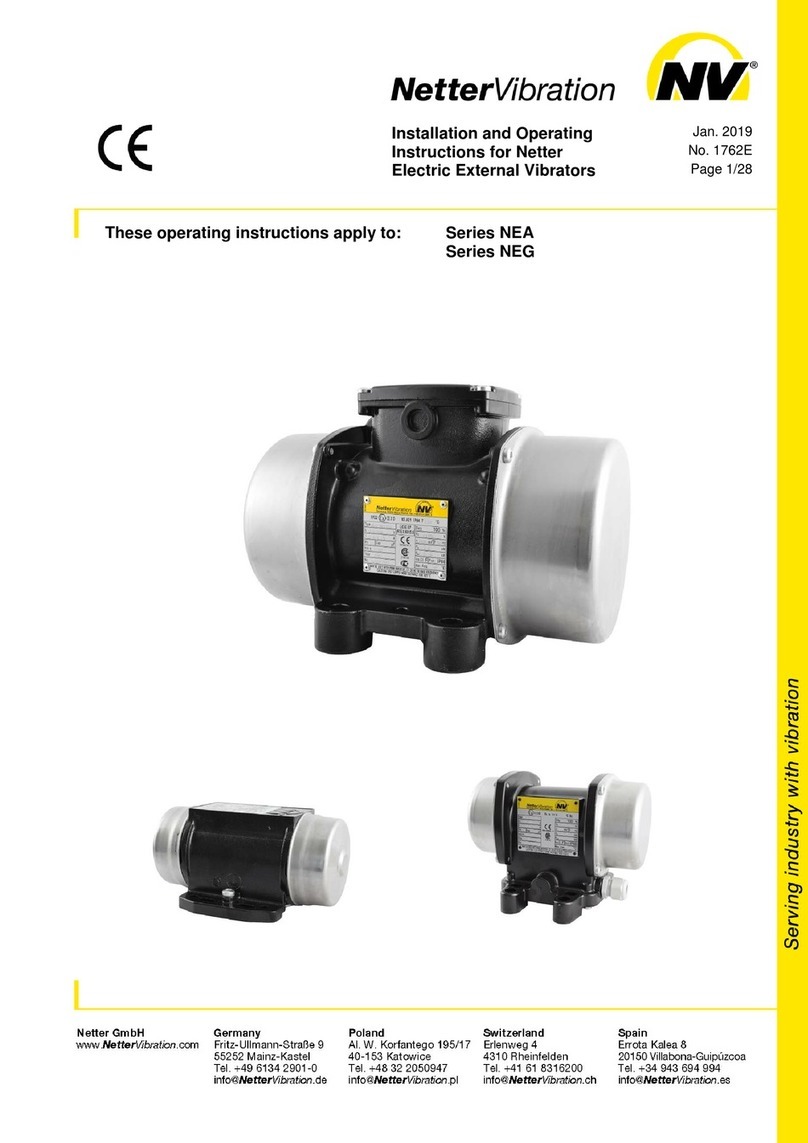
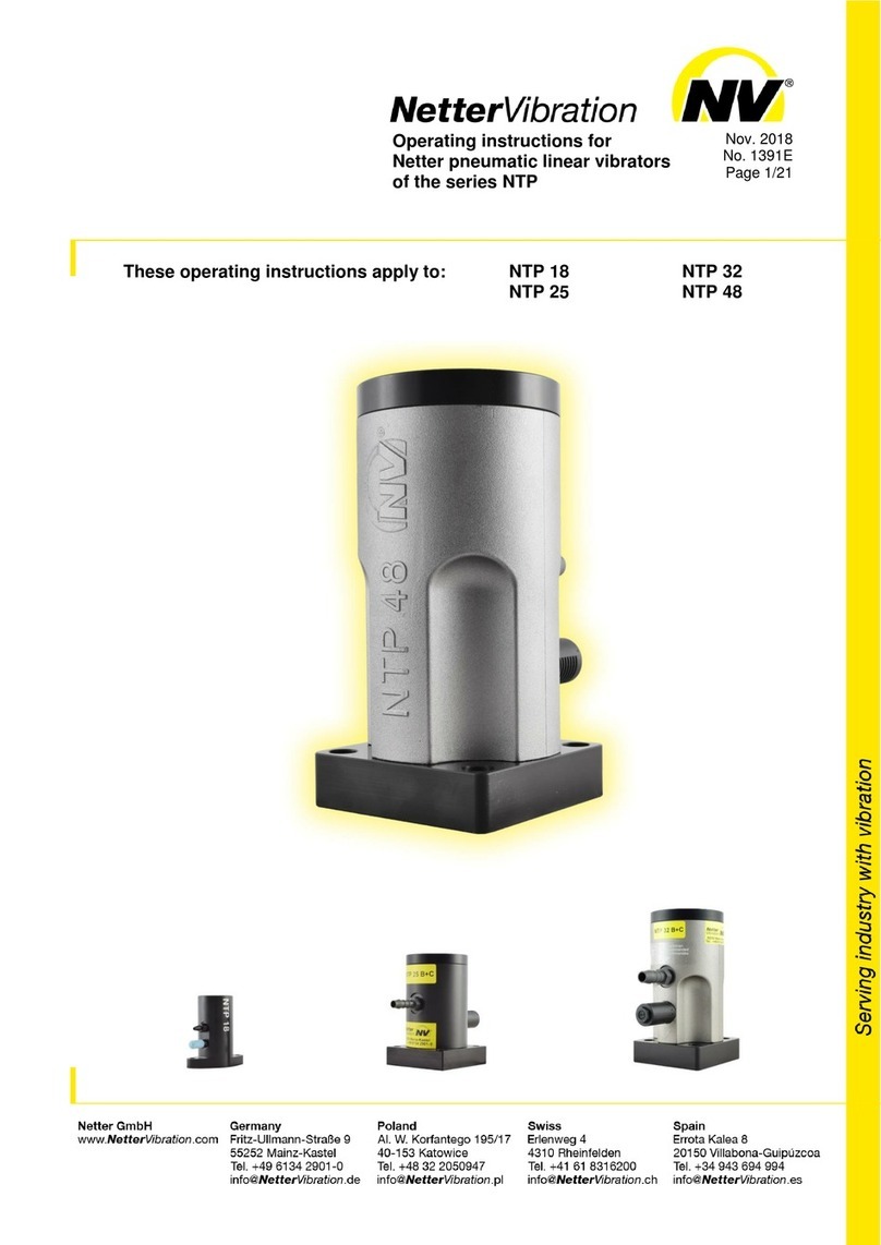
NetterVibration NTP Series User manual

Serving industry with vibration
Netter GmbH
Germany
United Kingdom
Switzerland
www.Netter
Vibration
.com
FritzUllmannStraße 9
2 Sandpiper Close
Erlenweg 4
55252 MainzKastel
Station Road
4310 Rheinfelden
Hednesford, WS12 4RN
Tel. +49 6134 29010
Tel. +44 1543 424990
Tel. +41 61 8316200
Fax +49 6134 290133
Fax +44 1543 423196
Fax +41 61 8311291
info@Netter
Vibration
.de
info@Netter
Vibration
.co.uk
info@Netter
Vibration
.ch
NetterVibration
Operating Instructions for June 2007
Netter Pneumatic Piston Vibrators BA No. 803 E
Series NTP Page 1/16
These operating instructions apply for: NTP 25
NTP 32
NTP 48
Important note:
Before use of the pneumatic piston vibrators series NTP read this operating instruc-
tion carefully and store afterwards.
Netter GmbH does not assume any liability for damage to property and persons if
the product has been technically modified or if the notes and regulations of these
operating instructions have not been observed.
This documentation is copyrighted. All rights, e.g. for translation into other lan-
guages, reprinting and copying of these operating instructions or parts hereof re-
main strictly reserved.

2
Contents
1GENERAL NOTES 3
2TECHNICAL DATA 4
3DESIGN AND FUNCTION 6
4SAFETY 7
5TRANSPORT AND STORAGE 8
6INSTALLATION 9
7START-UP / OPERATION 12
8SERVICE, MAINTENANCE 13
9TROUBLESHOOTING 15
10 SPARE PARTS 15
11 APPENDIX 16
11.1 Accessories 16
11.2 Disposal 16
11.3 Enclosures 16
Scope of Delivery:
Check the packaging for possible signs of transport damage. In the event
of damage to the packaging, check that the contents are complete and
undamaged. If there is any damage, inform the shipping agent. Compare
the scope of the delivery with the delivery note.

3
1 General Notes
Netter pneumatic piston vibrators series
NTP comply with the EC machine
directive 98/37/EG. Standards DIN EN
ISO 12100 part 1 and part 2 have been
particularly observed.
Series NTP pneumatic piston vibrators
generate linear vibrations or shaking
movements.
These vibrators are used to empty
hoppers and to drive conveyor troughs,
sieves and vibrating tables. General
applications are loosening, feeding,
compaction and separation of bulk
materials and the reduction of friction.
The drive medium is compressed air or
nitrogen, at a pressure of 1 bar to 6 bar.
Series NTP pneumatic piston vibrators
can be used for food production and in
wet areas, provided the corresponding
company operating regulations are
observed.
The frequency can be continuously
regulated by means of pressure regu-
lators or throttles built into the air sup-
ply lines and the amplitude can be con-
tinuously reduced by means of throttles
in the air discharge lines.
The following instruction and warning symbols are used in these operating instructions.
Note on important procedures Warning of a danger spot
Important note on procedures to
be especially observed Environmentally friendly disposal

4
2 Technical Data
Drive medium:
Clean (5 µm filter), lubricated compressed air or lubricated nitrogen
Unfiltered compressed air will lead to breakdown of the vibrators.
Operating pressure:
2 bar to 6 bar
The operating pressures must not be exceeded or fallen short of.
Timed operation is compulsory for NTP B+C vibrators
(e.g. duty time 5 s, pause time 25 s).
Ambient temperature:
Standard 5°C to 60°C
The operating temperatures must not be exceeded or fallen short of.
Special designs available upon request
Series NTP piston vibrators are
available in sizes 25, 32 und 48. In
the standard version NTP B+C, an
impact plate (elastomer disc) is
inserted in the base plate, which
creates a rubber hammer effect.
In version B, the impact plate is
removed and the piston strikes
against a cushion of air above the
base plate.
The elastomer insert can be replaced
by a steel impact plate (hard-
impacting, with high noise level).
An additional hard-impacting
alternative is to mount the vibrator
without a base plate.
Technical Data at 2 - 4 - 6 bar
B + C = soft-impacting (impact plate in base plate)
B = without base plate (quiet, due to air cushion)
The technical date are reference values and may vary depending on the application, further data available upon request.
We recommend consultation of the Netter GmbH application engineers. Subject to technical changes.
Noise Level

The noise level of an NTP is
dependent on the surface upon which
it is mounted. As a rule, the noise level
of the NTP 25 B (with silencer), at an
operating pressure of 6 bar, lies below
80 dB(A).
For NTP 32 B and 48 B, the noise level
at an operating pressure of 4 bar also
lies below 80 dB(A).
At higher air pressures or with an
elastomer insert C installed, the peak
pressure may exceed 85 dB(A),
depending on the mounting surface
and the pressure.
For hard-impacting installations
(without base plate), the noise level
lies considerably above 85 dB(A).
Duration of Operation:
Long periods of operation will change
the technical performance data (wear).
Please note when planning:
NTP B E piston vibrators will only start in every mounting position if a 3/2
way valve is fitted. If the air supply is regulated by means of a 3/2 way
valve, the piston vibrators will come to a standstill immediately after
switching off.
The use of filtered compressed air is compulsory for all devices.
Lubrication-free operation is possible.
The use of an oil-mister increases the machine life.
Dimensions
NTP 25 NTP 32 / NTP 48

6
3 Design and Function
The vibration is generated by a freely
oscillating differential pressure piston.
In the basic version NTP B+C, the
piston strikes against an elastomer
impact plate, creating a rubber
hammer effect.
Version B has no impact plate; the
piston swings noiselessly against a
cushion of air.
If the device is required to produce
hard impacts, either a steel plate is
inserted into the base plate or the base
plate is completely removed. This
results in hard impacts against the
surface to which the device is
attached.
The frequency can be continuously
adjusted via the operating pressure,
the amplitude is set by throttling the
exhaust air.
1
2
3
4
6
7
8
9
10
Housing
Piston
Base plate
Cover
Screw
Screw
Air inlet port
Air exhaust port
Impact plate

7
4 Safety
NTP vibrators operate using compressed
air at a pressure of up to 6 bar. All
hoses must therefore be securely
connected. If a pressurized hose
becomes loose it can cause injury. The
compressed air must therefore be shut
off before performing installation work.
Vibrators and parts of the construction
may become loose, due to vibration.
Falling parts can cause material
damage or injury. Screw locks and/or
Loctite or equivalent must therefore be
used.
Screwed connections should be
checked after 1 hour of operation and
then at regular intervals (generally once
per month) and tightened, if necessary.
In critical installation situations, it is
necessary to secure the vibrator with a
steel safety rope.
Jan. / Feb. / ...
Silencer:
Operation without a silencer should be avoided, so that the environment
is not subject to unnecessarily high noise levels.
Modifications:
Modifications to the device can alter the characteristics of the NTP or
destroy the device, and result in the rejection of all warranty claims.
Failure to comply with the operating instructions will also result in the
rejection of all warranty claims.
NTP B+C vibrators may only be operated in timed mode
(e.g. duty time 5 s, pause time 25 s).
NTP vibrators may also be operated in dusty or wet environments – even
under water, if the exhaust air is dissipated.

8
Drive medium:
Clean (5 µm filter), lubricated compressed air or lubricated nitrogen
Unfiltered compressed air will lead to breakdown of the vibrators.
Operating pressure:
2 bar to 6 bar
The operating pressures must not be exceeded or fallen short of.
Ambient temperature:
Standard 5°C to 60°C
The operating temperatures must not be exceeded or fallen short of.
Special versions available upon request
5 Transport and Storage
Check the packaging for possible signs of transport damage. In the event
of damage to the packaging, check that the contents are complete and
undamaged. If there is any damage, inform the shipping agent.
The vibrators are packed ready-to-
install.
The type label is attached to the vibra-
tor.
Accessories and add-on parts (grom-
mets, silencers) are delivered loosely,
unless otherwise agreed.
Special transport conditions are not
specified.
The units should be stored in a clean,
dry environment.
NTP piston vibrators must be oiled be-
fore going back into storage (pour ma-
chine oil into air inlet port and activate
shortly).
It is recommended that dirty devices
are cleaned (disassemble, rub deposits
off using oil if necessary, wipe clean,
reassemble).
The storage temperature should be be-
tween –40 °C and 60 °C.
(This does not apply to the operating
temperature; compare with chapter 4
SAFETY “Permissible Operating
Conditions”).

9
6 Installation
During installation, the safety regula-
tions in chapter 4 and the safety pre-
vention rules must be strictly observed!
Ensure that the compressed air supply is
shut off during installation or when
working on the vibrator and air supply
lines.
Mounting the Vibrator:
The housing of the piston vibrator is
screwed to the mass to be vibrated.
The mounting surfaces must be
absolutely level (±0.1mm flatness), so
that vibrator has full area contact and
the housing does not distort when the
fixing screws are tightened. The
surfaces should also be free of any
paint residues or weld burns. Tension in
the housing can cause mechanical
damage.
Directional vibrations are generated.
The working moment of the free-
swinging piston (M = mass x distance)
is determined by the amplitude.
In the standard version NTP B+C, the
piston strikes against an elastomer
impact plate, creating a rubber
hammer effect.
Version B has no impact plate,; the
piston swings noiselessly against a
cushion of air.
If the device is required to produce
hard impacts, either a steel plate is
inserted into the base plate or the base
plate is completely removed. This
results in hard impacts against the
surface to which the device is
attached.
Please consider during installation: The permissible temperature range
must not be exceeded or fallen short of during operation. Versions for
other temperature ranges available upon request.
In critical installation situations, it is necessary to secure the vibrator with
a safety rope.
10
The above diagram illustrates the possible applications:
A On vibration tables, for compaction, testing, etc.
B Under tables, on filters, for shaking, etc.
C On hoppers, for emptying, on vibrating troughs and sieves.
Use lock screws and nuts and a liquid adhesive (e.g. Loctite) to prevent
loosening.
The tightening torques are to be taken
from the following table. Higher tightening
torques can lead to the fracturing of
screws or tearing of threads.
Incorrect attachment of screws can lead
to detachment of the device. This can
result in personal injury and damage to
material!
Retightening:
Screwed connections should be retightened after 1 hour of operation
(after initial start-up) and then checked at regular intervals (generally
once per month) and tightened, if necessary.
Please consider during installation:
The permissible temperature range must not be exceeded or fallen short
of during operation, see Chapter 4 “Safety – Permissible Operating
Conditions”.
Versions for other temperature ranges available upon request.
Recommended Average Tightening Torques for Screws Property Class 8.8 on
NTP Housings (Screws as delivered, with no additional lubrication):
Type Thread
Tightening Torque
NTP 25 M 6 10.4 Nm
NTP 32 M 10 51 Nm
NTP 48 M 12 87 Nm
Always use a torque wrench and tighten the screws diagonally.

11
Air Supply Line:
The air resistance increases with the
length of the hose. The nominal widths
shown in the chart apply for hose
lengths of up to 3 m. Longer supply
lines require a larger cross-section.
Air Discharge Line:
The exhaust air can be discharged
through a hose.
In order for the piston vibrator to achieve
full power, the discharge hose must
have a greater nominal width than the
supply hose. A silencer must be fitted to
the free end.
Minimum Cross-Sections for Valves and Hoses:
TYPE Conn. Thread Hose Size 3/2 Way Valve
NTP 25 G 1/8 from NW 4 G 1/4, from NW 4
NTP 32 G 1/4 from NW 6 G 1/4, from NW 6
NTP 48 G 3/8 from NW 9 from G 3/8, from NW 9
1) Never use longer connecting threads than specified for the air supply
line (e.g. no tubes with male thread). The housing may deform – the
piston will then seize.
2) Ensure that no Teflon tape can enter the unit. This would cause
seizure. The first two windings of the thread should remain free!
3) The base plate must lie absolutely flat, otherwise the housing will
distort and the device will not start.
The drive medium must be clean (filtered).
Dirt causes vibrators to break down.
Filter recommended
Lubricated compressed air can be used
for all vibrators.
Oil lubrication:
Fill the oil-mist lubricator with acid-free
and resin-free pneumatic oil, ISO
viscosity class according to DIN 51519,
VG 5 to VG 15.
NTP 25 *) 0-1 drop/min
NTP 32 *) 1-2 drops/min
NTP 48 *) 1-2 drops/min
Recommendation: Klüber „AIRPRESS
15" for temperatures up to 60°C.
*) lubrication-free operation possible

12
Checklist for Installation
1)
2)
3)
Consider the expected operating temperature.
Mount the unit. Secure fastening screws.
Install the service unit (filter, mist lubricator, regulator, as required),
valve and supply line.
7 Start-Up / Operation
The start-up of the vibrators is possible
immediately after correct installation.
After filling the mist lubricator with oil,
the vibrator can be started and the
required drops/min set on the
lubricator. We recommend Klüber
„AIRPRESS 15“ oil for operating
temperatures of up to 60°C.
Attention: Reduced cross sections
cause throttling (pay attention to
nominal widths).
Standard Installation
Detailed drawings are available upon request.
Die NTP B+C vibrators may only be operated in timed mode.
A
60 second (max.) duty time must be followed by a 60 second (min.)
pause. Alternatively, short duty times (≤ 12 seconds) may be used with a
pause factor of 5. (Example: 5 seconds duty – 25 seconds pause).
Mist lubricator: Adjust the number of drops with the vibrator running
NTP 25: 0-1 drop/min
NTP 32: 1-2 drops/min
NTP 48: 1-2 drops/min

13
When using dried compressed air and
under extreme environmental
conditions, the installation of an
upstream mist lubricator is compulsory.
Regulation of Amplitude:
The amplitude can be regulated by
throttling the exhaust air (throttle fitted
in air discharge line).
This reduces the centrifugal force.
The frequency remains approximately
constant.
Recommendation: Only reduce
amplitude by up to approx. 50%. Lower
values can cause start-up problems.
Regulation of Frequency:
The frequency can be regulated by
reducing the air pressure before it
enters the NTP.
This also reduces the centrifugal force.
The amplitude remains approximately
constant.
The pressure reduction can be
achieved using a throttle with a
constant pre-pressure; a pressure
regulator is however more accurate.
Checklist for Start-Up:
1) Check hose connections before opening the compressed air supply.
2) Adjust the mist lubricator, if necessary.
3) Set the desired frequency on the pressure regulator, if necessary.
4) Set the desired amplitude by throttling the discharged air, if
necessary.
The vibrator attachment screws must be checked after 1 hour of operation
and tightened, if necessary.
8 Service, Maintenance
Please observe the safety regulations in chapter 4 when servicing
the device.
Retightening:
Screwed connections should be retightened after 1 hour of operation
(after initial start-up) and then checked at regular intervals (generally
once per month) and tightened, if necessary. The specified torque must be
observed (see chapter 6).

14
Before starting inspection or service
work, shut off the compressed air
supply and protect it against unwanted
activation!
Regularly check the attachment of the
vibrator, the compressed air supply and
upstream service unit, as well as the
silencer – preferably at monthly
intervals.
Jan. / Feb. / ...
Mist Lubricator: For devices with an
upstream mist lubricator, ensure that
the lubricator works correctly (does oil
content fall? Number of drops/min.?).
Refill oil.
Filter: Empty the filter as required,
clean the filter insert (wash out).
Cleaning: All NTP vibrators can be
externally cleaned using pressure wa-
ter, when the exhaust air is being dis-
charged or the exhaust opening is
closed. Pressure water must not enter
the piston chamber via the silencer.
Silencer: A blocked silencer causes the
vibrator to lose power. In extreme cases
it may even stop. The silencer should
therefore be regularly serviced and re-
placed, if necessary.
The service intervals are largely de-
pendent on the cleanliness of your
drive medium.
Additional notes can be found in
chapter 9 “Troubleshooting”.

15
9 Troubleshooting
Fault Possible Cause Remedy
Will not start Silencer Clean silencer
Compressed air supply Check pressure on device! Is enough
pressure available? Check valve. A 3/2
way valve is compulsory, so that the
supply line to the device is vented.
Cover loose
A
n unsealed cover causes standstill
Tighten screws.
Line cross-sections Observe minimum cross-sections. See
specifications under “Installation”.
Line between valve and
NTP B E too long
Causes slow starting and possibly
standstill of piston in mid-position. If
necessary, install a pilot-controlled 3/2
way valve in front of the vibrator.
Exhaust over-throttled Open up throttle. Check silencer (is air
clearance sufficient?).
Grommet thread too long Can cause deformation of housing (if
this has already occurred, return de-
vice!).
Distortion from mounting Check mounting surface is level.
Rattling Screws loose Check the fastening screws.
Power drop No lubrication Check that lubricator is working cor-
rectly.
Unit soiled Return device!
Wear Check device and piston for visible
signs of wear (if wear is evident, return
device!) See also notes in chapter 10
“Spare Parts”.
Specification Check size of device. Has the correct
size been selected?
Pressure too low Check pressure at the device inlet (!)
during operation. Increase pressure, if
necessary. Are the line cross-sections
OK?
10 Spare Parts
When ordering spare parts, please give the following details:
1. Type of unit
2. Description of spare part
3. Required quantity
Please note: Piston and housing are matched to each other and can only
be delivered together.

16
11 Appendix
11.1 Accessories
The following accessories are available (upon request) for piston NTP vibrators:
Description Remark
Hose material and fit-
tings For air supply and discharge, in various grades and di-
mensions
3/2 way valves For electric, pneumatic and manual activation
Throttle valves For amplitude regulation, manually adjustable or pneu-
matically controllable (for remote control)
Service units Filter, regulator, lubricator
Duty/pause controls Electric or pneumatic, for interval operation
Brackets For quick repositioning of vibrators on containers
Special versions: Atex conform Series NTP piston vibrators and devices
with stainless steel housings are available. Units for ex-
treme temperatures and for lubrication-free operation
available upon request.
11.2 Disposal
The parts are to be correctly disposed of, according to the material.
Material Specifications:
All parts of the vibrators can be recycled.
Housing: Aluminium
Cover : Aluminium
Piston: Steel
Srews: Stainless steel
All devices can be disposed of through Netter GmbH.
The applicable disposal prices are available upon request.
11.3 Enclosures
Enclosure(s):
• Declaration of Conformity
A
dditional information available upon
request:
• Brochure No 26 (NTP)
• Tips for building extraction troughs
with piston vibrators, and much
more.
Other manuals for NTP Series
3
This manual suits for next models
3
Table of contents
Other NetterVibration Power Tools manuals

NetterVibration
NetterVibration NTP Series User manual

NetterVibration
NetterVibration NEA Series User manual

NetterVibration
NetterVibration NED 605 User manual

NetterVibration
NetterVibration NCT Series User manual

NetterVibration
NetterVibration NTK Series User manual

NetterVibration
NetterVibration NTS 100/01 User manual