NetUP Streamer HD v3 8-24x User manual


NetUP Streamer HD v3 8-24x. User manual
2
Contents
Chapter 1 Product Introduction ..........................................................................................................3
1.1 Outline...........................................................................................................................................3
1.2 Main Features................................................................................................................................3
1.3 Principle Chart (Each Encoder Module).........................................................................................4
1.4 Specifications.................................................................................................................................4
1.5 Appearance and Illustration..........................................................................................................5
Chapter 2 Installation Guide................................................................................................................7
2.1 Acquisition Check ..........................................................................................................................7
2.2 Installation Preparation.................................................................................................................7
2.3 Wire’s Connection .........................................................................................................................8
2.4 Signal Cable Connection................................................................................................................9
Chapter 3 WEB NMS Operation ........................................................................................................10
3.1 login.............................................................................................................................................10
3.2 Operation.....................................................................................................................................11
Chapter 4 Troubleshooting................................................................................................................18

NetUP Streamer HD v3 8-24x. User manual
3
Chapter 1 Product Introduction
1.1 Outline
NetUP Streamer HD v.3 is a professional HD/SD audio & video encoding device. It has 8/16/24 HDMI
inputs for option. Every 8 HDMI ports share one encoder module with each module supporting 1MPTS
and 8 SPTS output. Its high integration and cost effective design makes the device widely used in
varieties of digital distribution systems such as cable TV digital head-end, digital TV broadcasting etc.
1.2 Main Features
8 HDMI inputs with 8 SPTS and 1 MPTS output (each encoder module), max 24 HDMI inputs
MPEG4 AVC/H.264 video encoding format
MPEG1 Layer II, LC-AAC,HE-AAC audio encoding format and AC3 Pass Through, and audio gain
adjustment
IP output over UDP and RTP/RTSP protocol; 1 ASI out as mirror of MPTS (Optional)
Support QR code, LOGO, caption insertion (Language Supported: 中文, English, , ไทย, ,
русский, for more languages please consult us…)
Support “Null PKT Filter” function
Control via web management, and easy updates via web
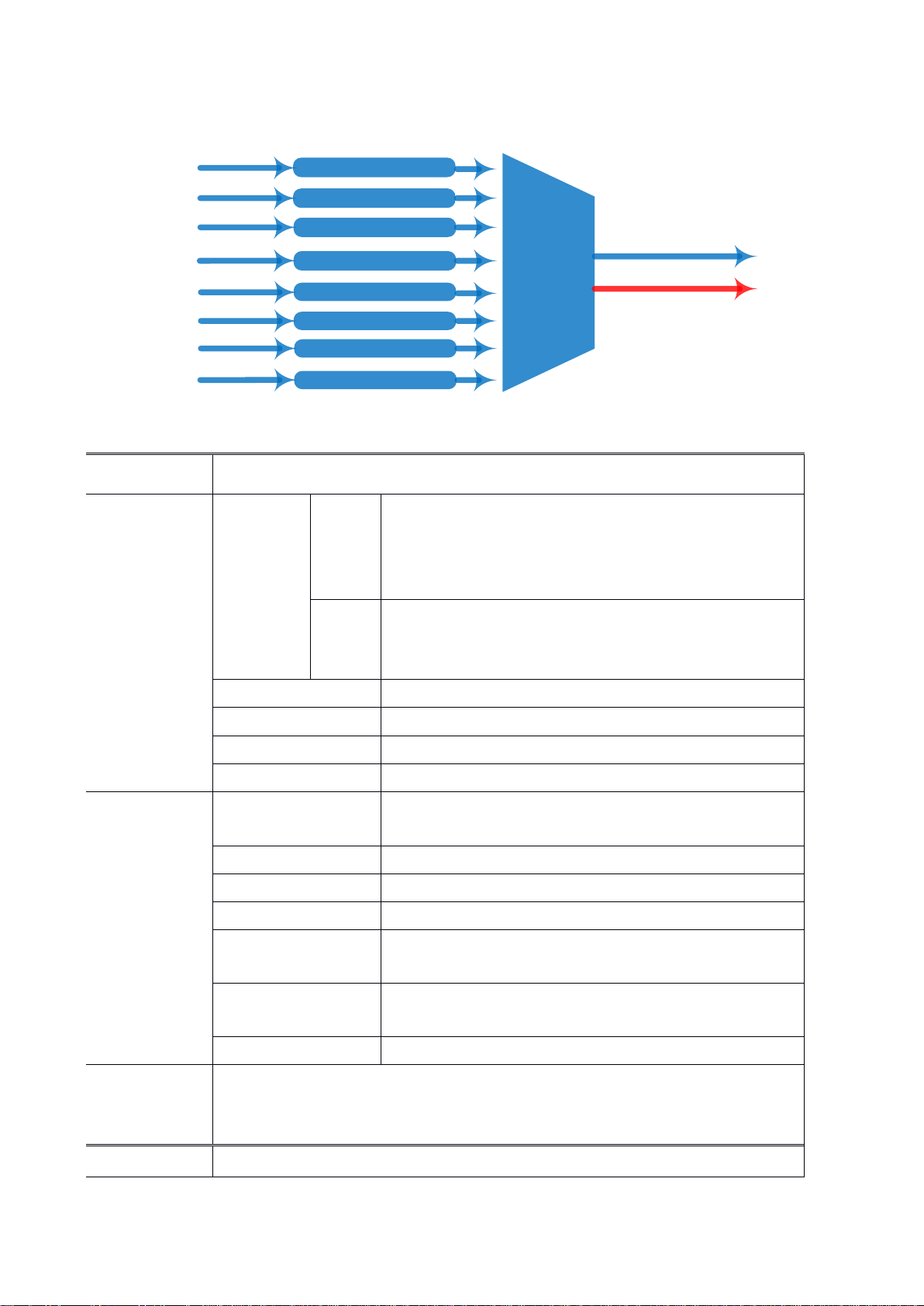
1.3 Principle Chart (Each Encoder Module)
Mux
MPEG4 AVC/H.264 Encoding
HDMI #1
HDMI #2
HDMI #3
HDMI #4 1 MPTS and 8 SPTS
MPEG4 AVC/H.264 Encoding
MPEG4 AVC/H.264 Encoding
MPEG4 AVC/H.264 Encoding
MPEG4 AVC/H.264 Encoding
MPEG4 AVC/H.264 Encoding
MPEG4 AVC/H.264 Encoding
MPEG4 AVC/H.264 Encoding
HDMI #8
HDMI #7
HDMI #6
HDMI #5 ASI out(Optional)
As copy of MPTS
1.4 Technical specification
Input
8/16/24 HDMI inputs
Video
Resolution
input
1920×1080_60P, 1920×1080_60i,
1920×1080_50P, 1920×1080_50i,
1280×720_60P, 1280×720_50P,
720 x 576_50i,720 x 480_60i
Output
1920×1080_30P, 1920×1080_25P,
1280×720_30P, 1280×720_25P,
720 x 576_25P, 720 x 480_30P
Encoding
MPEG-4 AVC/H.264
Bit-rate
1~13Mbps each channel
Rate Control
CBR/VBR
GOP Structure
IP…P (P Frame adjustment, without B Frame )
Audio
Encoding
MPEG-1 Layer 2, LC-AAC, HE-AAC and AC3 Pass
through
Sampling rate
48KHz
Resolution
24-bit
Audio Gain
0-255 Adjustable
MPEG-1 Layer 2 Bit-
rate
48/56/64/80/96/112/128/160/192/224/256/320/384
kbps
LC-AAC Bit-rate
48/56/64/80/96/112/128/160/192/224/256/320/384
kbps
HE-AAC Bit-rate
48/56/64/80/96/112/128 kbps
Stream
output
IP output through DATA (GE) over UDP and RTP/RTSP protocol
(8 HDMI inputs with 8 SPTS and 1MPTS output for each encoder board)
1 ASI out as mirror of MPTS (Optional as order)
Network management(WEB)

System
function
Chinese and English language
Ethernet software upgrade
Miscellaneous
Dimension
(W×L×H)
482mm×328mm×44mm
Environment
0~45℃(work);-20~80℃(Storage)
Power
requirements
AC 110V± 10%, 50/60Hz, AC 220 ± 10%, 50/60Hz
1.5 Appearance and Illustration
Front Panel Illustration:
1U chassis (three encoder modules) illustration:
1 2 3
1
Module 3 NMS and Data port and indicators
Data Port (for IP Signal Output)
NMS (Network Management Port)
2
Module 2 NMS and Data port and indicators
3
Module 1 NMS and Data port and indicators
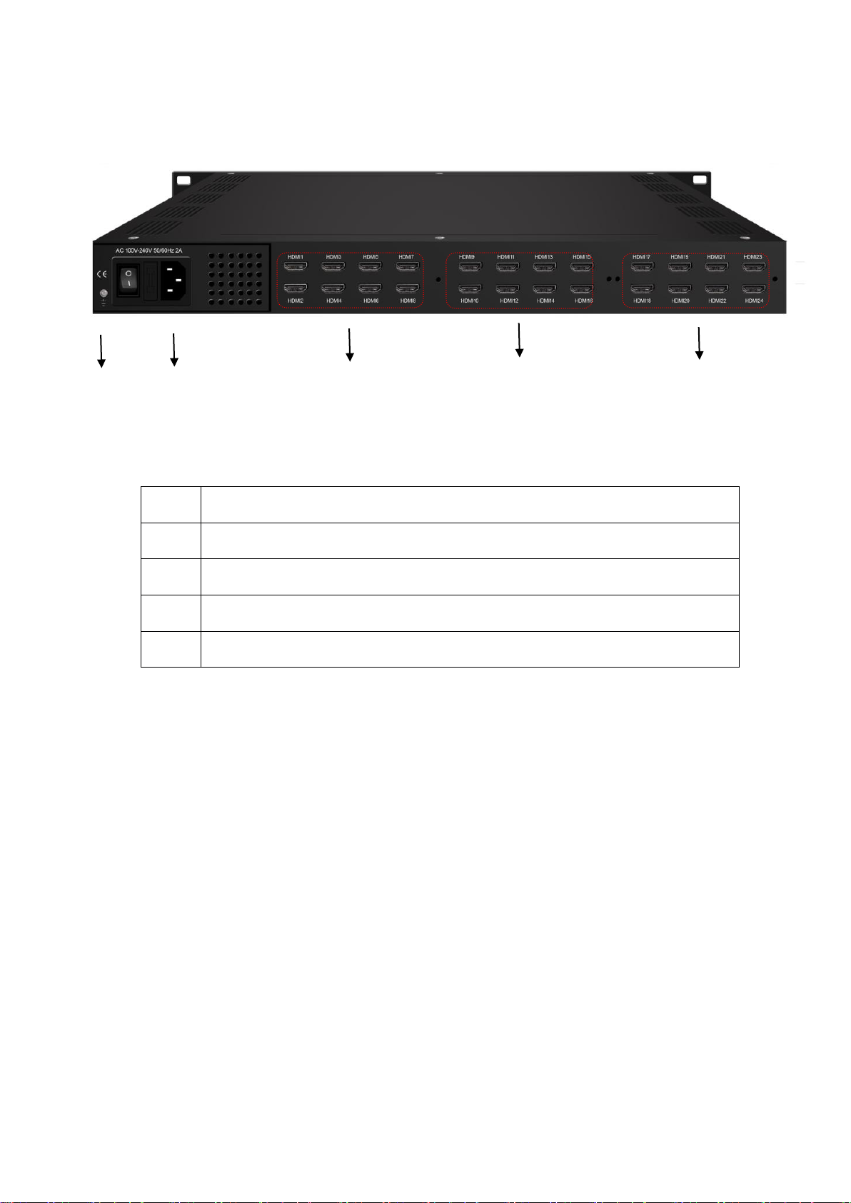
Rear Panel Illustration:
1 2 3 4 5
1
Grounding Pole
2
Power Switch and socket
3
Module 1: HDMI 1-8
4
Module 2: HDMI 9-16
5
Module 3: HDMI 17-24

Chapter 2 Installation Guide
2.1 Acquisition Check
When users open the package of the device, it is necessary to check items according to packing list.
Normally it should include the following items:
NetUP Streamer HD v.3
Power Cord
HDMI cables
If any item is missing or mismatching with the list above, please contact local dealer.
2.2 Installation Preparation
When users install device, please follow the below steps. The details of installation will be described at
the rest part of this chapter. Users can also refer rear panel chart during the installation.
The main content of this chapter including:
Checking the possible device missing or damage during the transportation
Preparing relevant environment for installation
Installing Encoder
Connecting signal cables
Connecting communication port (if it is necessary)
2.2.1 Device’s Installation Flow Chart is Illustrated as following:
Connecting
Grouding
Wire and
Power
Cord
Acquisition
Check Fixing
Device Setting
Parameter Running
Device
Connecting
Signal Wire
2.2.2 Environment Requirement
Item
Requirement
Machine Hall Space
When user installs machine frame array in one machine hall,
the distance between 2 rows of machine frames should be
1.2~1.5m and the distance against wall should be no less than
0.8m.
Machine Hall Floor
Electric Isolation, Dust Free
Volume resistivity of ground anti-static material:
1X10⁷~1X10¹⁰,Grounding current limiting resistance: 1M
(Floor bearing should be greater than 450Kg/㎡)

Environment
Temperature
5~40℃(sustainable ),0~45℃(short time),
installing air-conditioning is recommended
Relative
Temperature
20%~80% sustainable 10%~90% short time
Pressure
86~105KPa
Door & Window
Installing rubber strip for sealing door-gaps and dual level
glasses for window
Wall
It can be covered with wallpaper, or brightness less paint.
Fire Protection
Fire alarm system and extinguisher
Power
Requiring device power, air-conditioning power and lighting
power are independent to each other. Device power requires
AC power 220V 50Hz. Please carefully check before running.
2.2.3 Grounding Requirement
All function modules’ good grounding designs are the basis of reliability and stability of devices. Also,
they are the most important guarantee of lightning arresting and interference rejection. Therefore,
the system must follow this rule.
Coaxial cable’s outer conductor and isolation layer should keep proper electric conducting with the
metal housing of device.
Grounding conductor must adopt copper conductor in order to reduce high frequency impedance, and
the grounding wire must be as thick and short as possible.
Users should make sure the 2 ends of grounding wire well electric conducted and be antirust.
It is prohibited to use any other device as part of grounding electric circuit
The area of the conduction between grounding wire and device’s frame should be no less than 25mm2.
2.2.4 Frame Grounding
All the machine frames should be connected with protective copper strip. The grounding wire should be
as short as possible and avoid circling. The area of the conduction between grounding wire and grounding
strip should be no less than 25mm2.
2.2.5 Device Grounding
Connecting the device’s grounding rod to frame’s grounding pole with copper wire.
2.3 Wire’s Connection

The grounding wire conductive screw is located at the right end of rear panel, and the power switch, fuse,
power supply socket is just beside ,whose order goes like this, power switch is on the left ,power supply
socket is on the right and the fuse is just between them.
Connecting Power Cord
User can insert one end into power supply socket, while insert the other end to AC power.
Connecting Grounding Wire
When the device solely connects to protective ground, it should adopt independent way, say, share
the same ground with other devices. When the device adopts united way, the grounding resistance
should be smaller than 1Ω.
Caution:
Before connecting power cord to NetUP Streamer HD v.3, user should set the power switch to “OFF”.
2.4 Signal Cable Connection
The signal connections include the connection of input signal cable and the connection of output signal
cable. The details are as follows:
2.4.1 HDMI input cable illustration:
2.4.2 Network Cable illustration (CAT5):
Chapter 3 WEB NMS Operation
NetUP Streamer HD v.3 does not support front buttons and LCD, users can only control and set the
configuration in computer by connecting the device to web NMS Port. User should ensure that the
computer’s IP address is different from the NetUP Streamer HD v.3 IP address; otherwise, it would cause
IP conflict.
3.1 login
The default IP address of this device is 192.168.0.136 for 8x model.
For model 16x the IP addresses are 10.0.0.101, 10.0.0.102.
For model 24x: 10.0.0.101, 10.0.0.102, 10.0.0.103
Connect the PC (Personal Computer) and the device with net cable, and use ping command to confirm
they are on the same network segment.
I.G. the PC IP address is 192.168.99.252, we then change the device IP to 192.168.99.xxx (xxx can be 0 to
255 except 252 to avoid IP conflict).
Use web browser to connect the device with PC by inputting the Encoder’s IP address in the browser’s
address bar and press Enter.
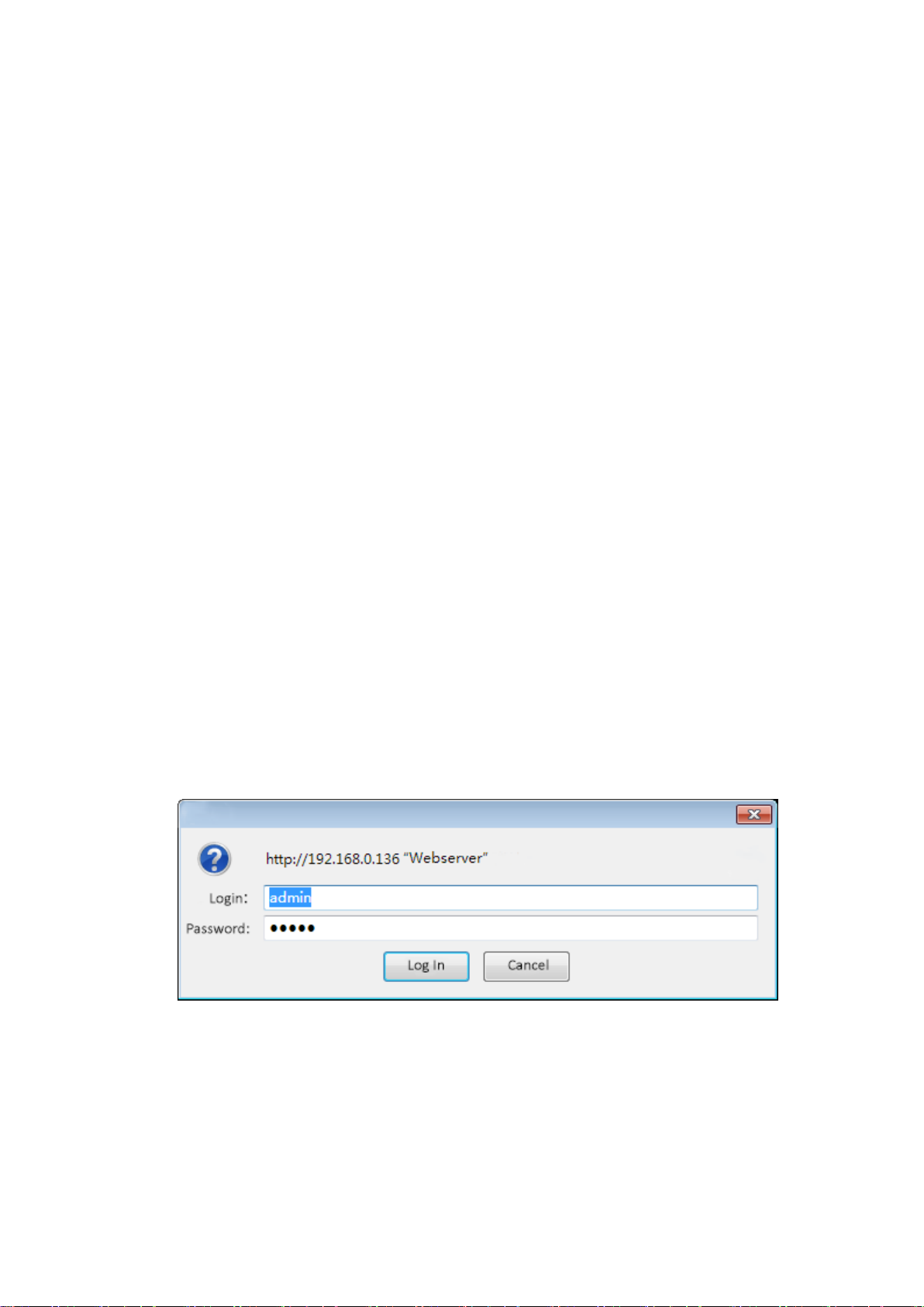
It will display the Login interface as Figure-1. Input the Username and Password (Both the default
Username and Password are “admin”.) and then click “LOGIN” to start the device setting.
Figure-1
3.2 Operation
When we confirm the login, it will display the WELCOME interface as Figure-2.
Figure-2
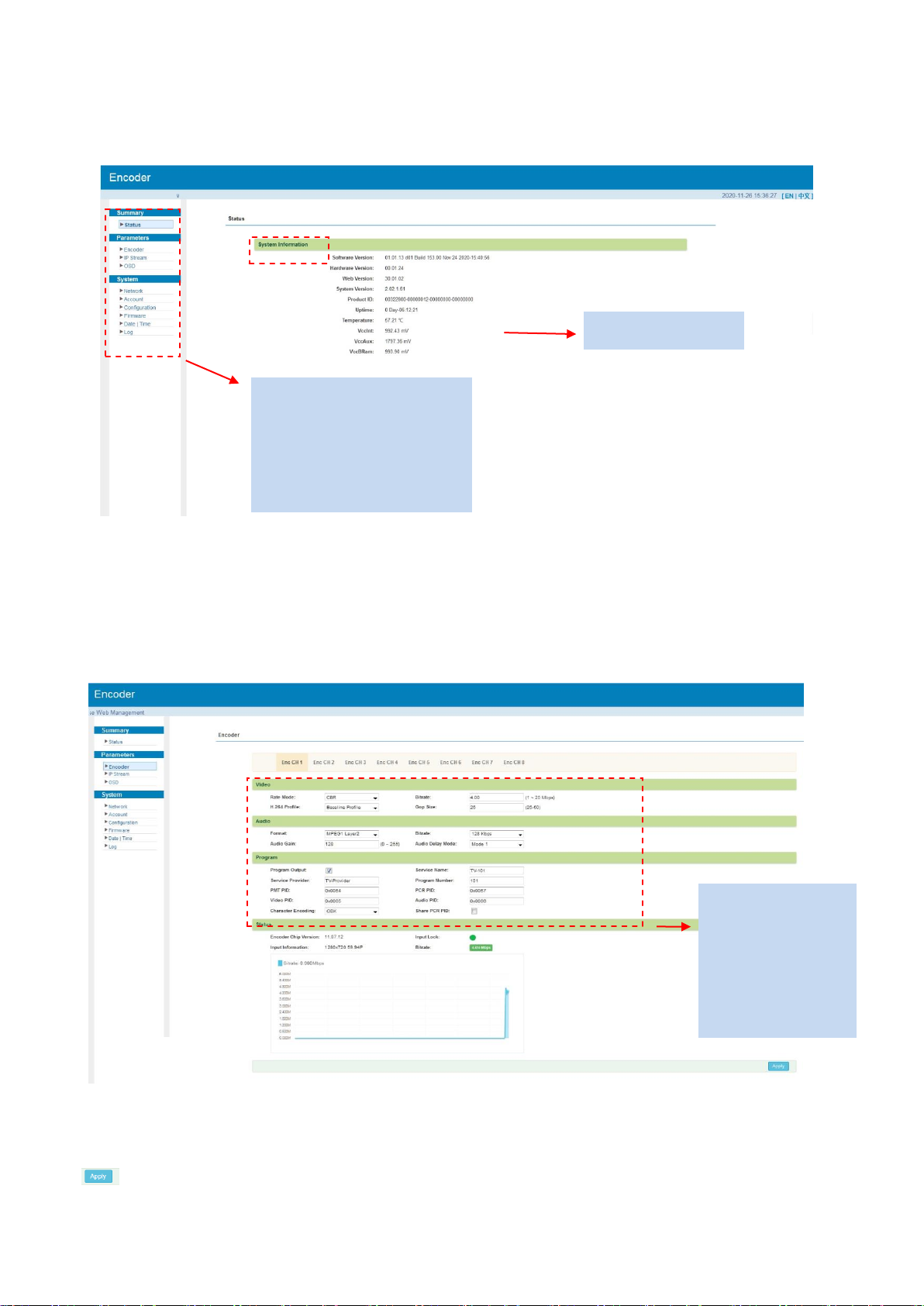
Parameters →Encoder
Encode Channel 1-8:
From the menu on upper side of the web page, clicking “Enc CH 1-8”, it will display the each encode
channel information of the program from the HDMI input port as Figure-3.
Figure-3
Click this button to apply the modified parameters.
Video and Audio
Settings for
program: User
can edit any item
listed as needed.
User can click any item
here to enter the
corresponding interface
to check information or
set the parameters.
System information
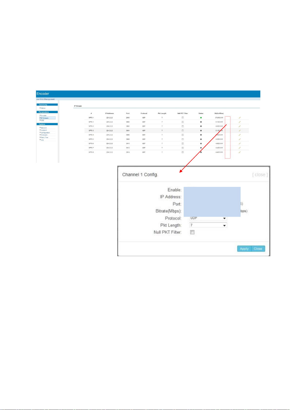
Parameters →IP Stream
NetUP Streamer HD v.3 supports TS to output in IP (8 SPTS) format through the DATA port.
When users click “IP Stream”, it will display the interface as Figure-4 where to set IP out parameters.
(For Data 1000M GE port)
Figure-4
Click pen icon to
edit IP output
parameters

Parameters →OSD
Clicking “OSD”, it will display the interface where to configuration the OSD parameters as Figure-5/6/7.
Figure-5
Figure-6
Select to configure logo, caption or QRcode
Select program1-8 to apply the logo insertion, or
you can select “all” to apply all programs
Click here to confirm the LOGO you selected
Browse and select
the Logo which has
been created
Put your logo everywhere
Enter your
text here
Put your caption anywhere
Select the text color and
background color
Set when to show caption. So do
Logo and QRCode.

Figure-7
System→ Network:
Clicking “Network”, it will display the interface as Figure-8 where to set NMS and DATA parameters.
Figure-8
System → Account:
Clicking “Account”, it will display the screen as Figure-9 where to set the login account and password for
the web NMS. Both the current username and password are “admin”.
Put the QRcode everywhere
Browse and select the
QRcode which has been
created
Input the QRcode URL here
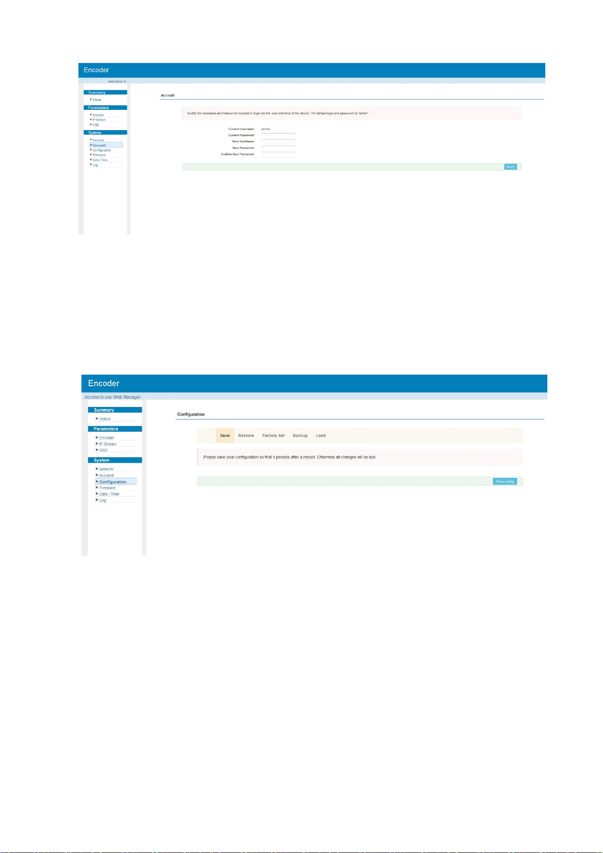
Figure-9
System → Configuration:
Clicking “Configuration”, it will display the screen as Figure-10 where to save/ restore/factory set/
backup/ load your configurations.
Figure-10
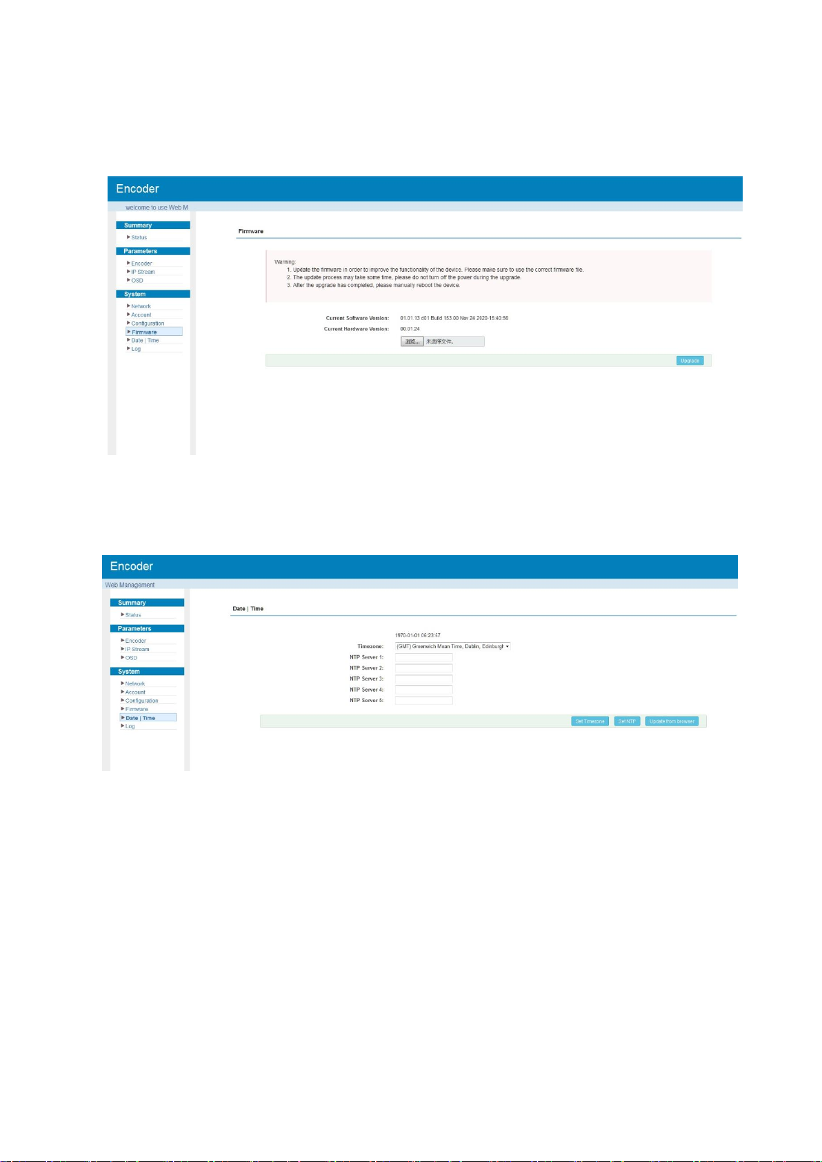
System → Firmware:
Clicking “Firmware”, it will display the screen as Figure-11 where to update firmware for the encoder.
Figure-11
System → Date/Time:
Clicking “Date/Time”, it will display the screen as Figure-12 where to set date and time for the device.
Figure-12

System → Log:
Clicking “Log”, it will display the log interface as Figure-13 where to check or export the Kernel/System
log.
Figure-13

Chapter 4 Troubleshooting
Check the following before troubleshooting:
Whether the server room is well ventilated and hot air from the back panel of the device is
effectively removed?
Does the supply voltage meet the power requirements of the device?
Are all cables connected correctly?
Turn off the device and unplug the power cord in the following cases:
The power cord or socket is damaged.
A liquid is splashed on the device.
A short circuit has occurred.
The device is in damp environment.
The device suffered from physical damage.
Longtime idle.
After switching on and restoring to factory setting, device still cannot work properly.
Maintenance needed.
Frequent on and off switching is prohibited; the interval between switching the device on and off must
be more than 10 seconds
Table of contents
Other NetUP Media Converter manuals


