netvox R718PA22 User manual

Model:R718PA22
Wireless Bottom-Mounted Ultrasonic Liquid Level
Sensor
0
Wireless Bottom-Mounted
Ultrasonic Liquid Level Sensor
R718PA22
User manual
Copyright© Netvox Technology Co., Ltd.
This document contains proprietary technical information which is the property of NETVOX Technology. It
shall be maintained in strict confidence and shall not be disclosed to other parties, in whole or in part, without
written permission of NETVOX Technology. The specifications are subject to change without prior notice.

1
Table of Content
1. Introduction................................................................................................2
2. Appearance.................................................................................................2
4. Main Characteristics ..................................................................................3
5. Operation....................................................................................................3
6. Data Report ................................................................................................4
7. Installation..................................................................................................7
7.1 Install the sensor at the bottom of the container / tank: .....................7
7.2 How to find the correct detection point..............................................9
8. Important Maintenance Instruction..........................................................10
2
1. Introduction
The R718PA22 is a wireless communication device that measures the liquid level with an ultrasonic liquid level sensor.
Ultrasonic liquid level sensor installed at the bottom of the container, it may measure water, gasoline, diesel and small, medium,
large capacity storage tanks (metal, plastic, glass material). R718PA22 main unit and the ultrasonic liquid level sensor
communicate via RS485 interface, and the detected data is sent to the other equipment shown which employs compliance
LoraWANTM wireless communication protocol standards.
LoRa Wireless Technology:
LoRa is a wireless communication technology dedicated to long distance and low power consumption. Compared with other
communication methods, LoRa spread spectrum modulation method greatly increases to expand the communication distance.
Widely used in long-distance, low-data wireless communications. For example, automatic meter reading, building automation
equipment, wireless security systems, industrial monitoring. Main features include small size, low power consumption,
transmission distance, anti-interference ability and so on.
LoRaWAN:
LoRaWAN uses LoRa technology to define end-to-end standard specifications to ensure interoperability between devices and
gateways from different manufacturers.
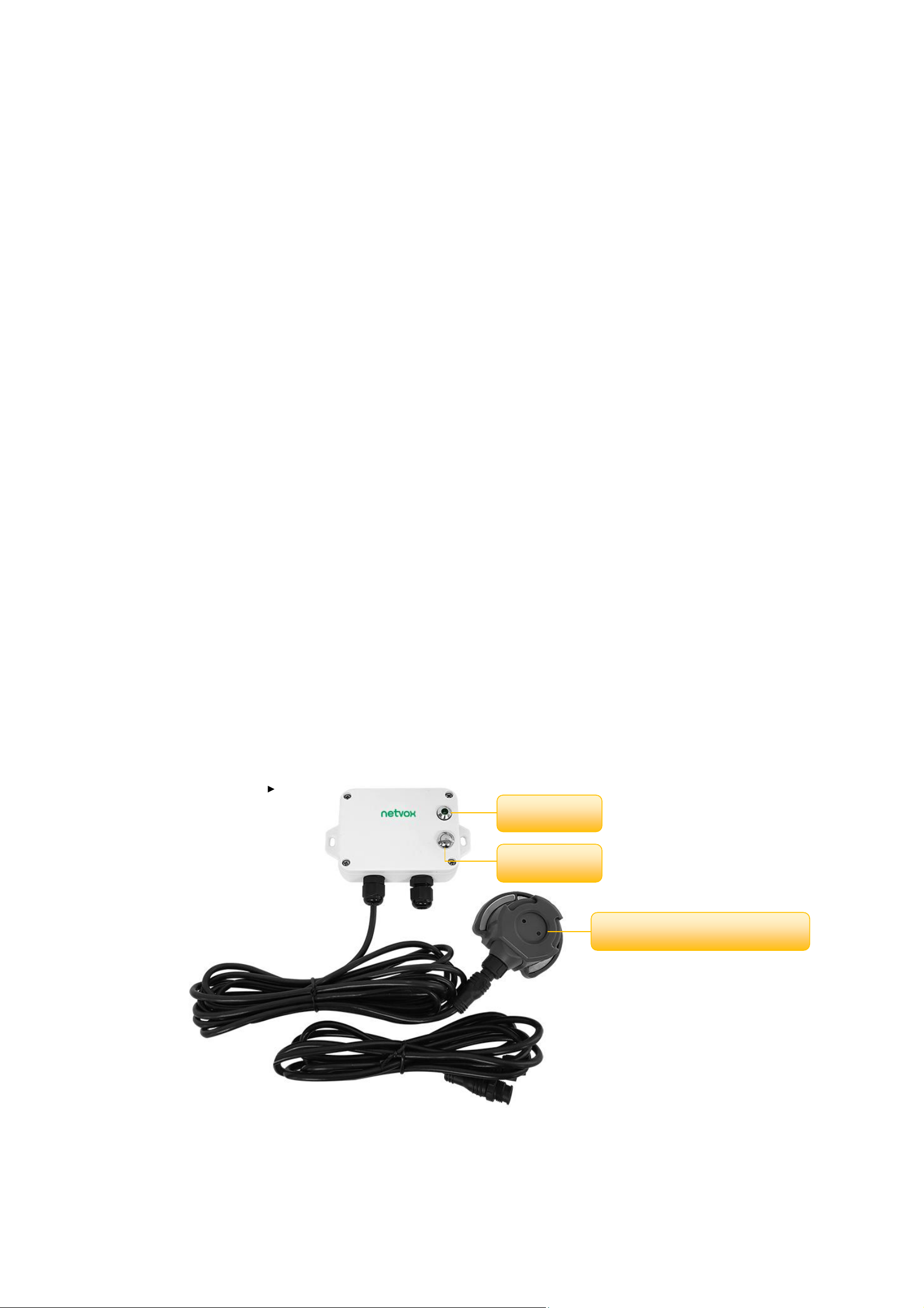
2. Appearance
Indicator
Function Key
Ultrasonic Liquid Level Sensor

3
4. Main Characteristics
⚫Adopt SX1276 wireless communication module
⚫DC 12V adapter power supply
⚫IP Rating: Main body - IP65/IP67 (optional), ultrasonic probe - IP67
⚫RS485 communication
⚫The base is attached with a magnet that can be attached to a ferromagnetic material object
⚫Compatible with LoRaWANTM Class A
⚫Frequency hopping spread spectrum technology
⚫Configuration parameters can be configured through third-party software platforms
⚫Data can be read and alerts can be set via SMS text and email (optional)
⚫Applicable to third-party platforms: Actility / ThingPark / TTN / MyDevices / Cayenne
5. Operation
On/Off
Power on
External 12V power supply
Turn on
Press and hold the function key for 3 seconds till the green indicator flashes once.
Turn off
(Restore to factory setting)
Press and hold the function key for 5 seconds till the green indicator flashes for 20 times.
Power off
Remove power
Note:
1. At 1st -5th second after power on, the device will be in engineering test mode.
2. Remove and supply the power; the device is at off state by default.
3. On/off interval is suggested to be about 10 seconds to avoid the interference of capacitor
inductance and other energy storage components.
Network Joining
Never joined the network
(Or at factory setting)
Turn on the device to search the network.
The green indicator stays on for 5 seconds: success
The green indicator remains off: fail
Had joined the network
(Not at factory setting.)
Turn on the device to search the previous network.
The green indicator stays on for 5 seconds: success
The green indicator remains off: fail
Fail to join the network
(when the device is on)
Suggest to check the device verification information on the gateway or consult your
platform server provider.

4
Function Key
Press and hold for 5 seconds
Restore to factory setting / Turn off
The green indicator flashes for 20 times: success
The green indicator remains off: fail
Press once
The device is in the network: The green indicator flashes once
The device is not in the network: The green indicator remains off
6. Data Report
When the device is powered on, it will immediately send a version report and a report of the liquid level status, depth and
temperature.
Before any configuration, the device sends data according to the default configuration.
Default setting:
Max time: Max Interval
Minimum time: Min Interval (detect the current voltage value every Min Interval by default)
Battery Voltage Change: 0x01 (0.1V) //R718PA22 is power by adapter, the value invalid
Depth Change: 0x0001 (1mm)
TemperatureChange: 0x01 (1 ℃)
Note:
The data transmission period of the device has been programmed.
The interval between two reports must be the minimum time
When Battery is 0x00, it represents powered by DC/AC power source
The data report can be decoded by the Netvox LoRaWANApplication Command document and
http://www.netvox.com.cn:8888/page/index
Data report configuration and sending period are as following:
Min. Interval
(Unit:second)
Max. Interval
(Unit:second)
Reportable Change
Current Change≥
Reportable Change
Current Change<
Reportable Change
Any number between
1~65535
Any number between
1~65535
Can not be 0.
Report
per Min. Interval
Report
per Max. Interval
5
Example of ConfigureCmd
FPort:0x07
Bytes
1
1
Var (Fix =9 Bytes)
CmdID
DeviceType
NetvoxPayLoadData
CmdID–1 byte
DeviceType–1 byte –Device Type of Device
NetvoxPayLoadData–var bytes (Max=9bytes)
Description
Device
Cmd
ID
Device
Type
NetvoxPayLoadData
Config
ReportReq
R718
PA22
0x01
0x9B
MinTime
(2bytes Unit:s)
MaxTime
(2bytes Unit:s)
BatteryChange
(1byte Unit:0.1v)
DepthChange
(2bytes,Unit:1mm)
Temperature
Change
(1byte,Unit:1℃)
Reserved
(1Bytes,Fixed
0x00)
Config
ReportRsp
0x81
Status
(0x00_success)
Reserved
(8Bytes,Fixed 0x00)
ReadConfig
ReportReq
0x02
Reserved
(9Bytes,Fixed 0x00)
ReadConfig
ReportRsp
0x82
MinTime
(2bytes Unit:s)
MaxTime
(2bytes Unit:s)
BatteryChange
(1byte Unit:0.1v)
DepthChange
(2bytes,Unit:1mm)
TemperatureCha
nge
(1byte,Unit:1℃)
Reserved
(1Bytes,Fixed
0x00)
SetMeasure
TypeReq
0x03
Measure type(1byte)
0x01_water,
0x02_gasoline,
0x03_diesel oil
Reserved
(8Bytes,Fixed 0x00)
SetMeasure
TypeRsp
0x83
Status
(0x00_success)
Reserved
(8Bytes,Fixed 0x00)
GetMeasure
TypeReq
0x04
Reserved
(9Bytes,Fixed 0x00)
GetMeasure
TypeRsp
0x84
Measure type(1byte)
0x01_water,
0x02_gasoline,
0x03_diesel oil
Reserved
(8Bytes,Fixed 0x00)
(1) Configure device parameters MinTime = 1min, MaxTime = 1min, BatteryChange = 0.1v, Depth Change = 5mm,
TemperatureChange = 2 ℃
Downlink: 019B003C003C0100050200
The device returns:
819B000000000000000000 (Configuration succeeded)
819B010000000000000000 (Configuration failed)
6
(2) Read device configuration parameters
Downlink: 029B000000000000000000
The device returns:
829B003C003C0100050200 (current device configuration parameters)
(3) Configure device measure type: 01 = Water, 02 = Gasoline, 03 = Diesel oil
Downlink: 039B020000000000000000 // Gasoline
The device returns:
839B000000000000000000 (Configuration succeeded)
839B010000000000000000 (Configuration failed)
(4) Read device configuration parameters
Downlink: 049B000000000000000000
The device returns:
849B020000000000000000 (current device configuration parameters)
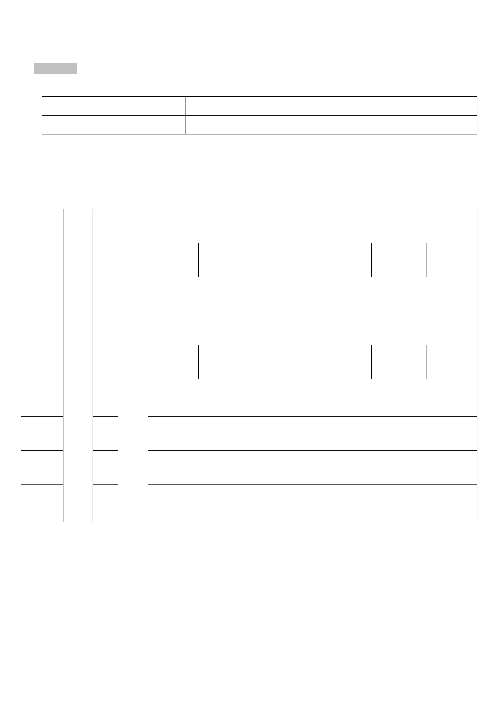
Example for MinTime/MaxTime logic:
Example#1 based on MinTime = 1 Hour, MaxTime= 1 Hour
MaxTime MaxTime
(MinTime) (MinTime)
0H 1H 2H
Note:
MaxTime=MinTime. Data will only be report according to MaxTime (MinTime) duration regardless ON/OFF value.
Example#2 based on MinTime = 15 Minutes, MaxTime= 1 Hour
MaxTime
MinTime MinTime MinTime MinTime
0H 15th M 30th M 45th M 1H 2H
Collects data
REPORTS
Collects data
REPORTS
Collects data
REPORTS
Collects data
REPORTS
Collects data
REPORTS
Collects data
Does not report

7
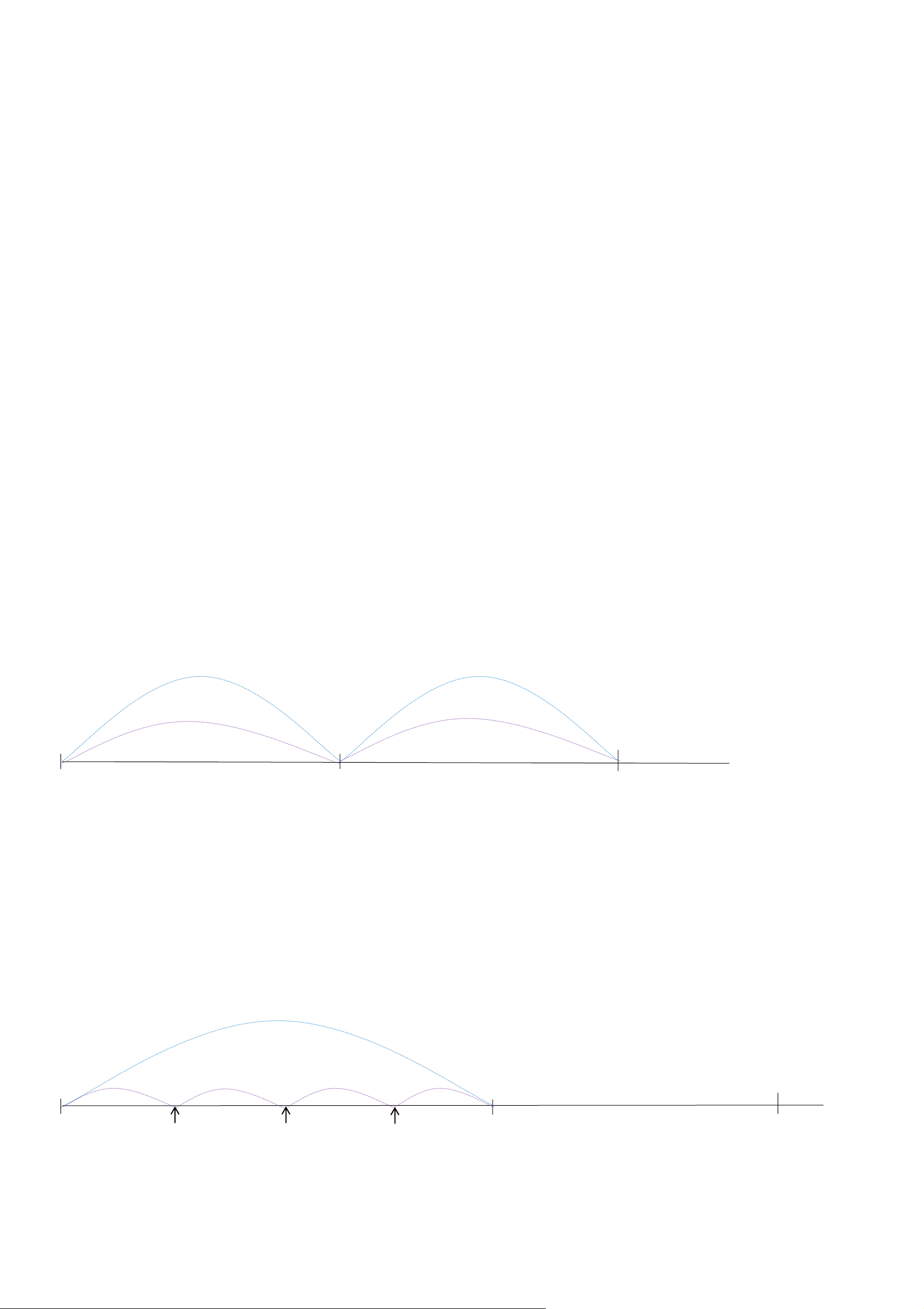
Example#3 based on MinTime = 15 Minutes, MaxTime= 1 Hour
MaxTime
MinTime MinTime MinTime MinTime MinTime MinTime
0H 15th M 30th M 45th M 1H 1H15thM1H30thM
7.Installation
The data obtained by the ultrasonic level sensor is the actual liquid height + the thickness of the bottom of the container.
The container material can be metal or plastic.
During the installation test, different test liquids (water, diesel, gasoline) can be configurated first.
7.1 Install the sensor at the bottom of the container / tank:
1. Power on first to see if the sensor is working normally.
The red light flashing on the sensor indicates that the sensor can work normally, as shown in the figure.
Collects data
REPORT
Collects data
Does not report
Collects data
REPORTS
Collects data
Does not report
Collects data
Does not report
Collects data
Does not report
Collects data
REPORT
The status changed

8
2. Place the container or tank in a horizontal position, preferably the angle between the container or tank and the horizontal plane
is less than 2 degrees.
3. Make sure the container / tank is full or at least 2/3 of the liquid.
4. Find best check-point for installing the sensor (the bottom of the container should be kept clean).
a. Apply some coupling gel on the sensor surface.
b. Place the sensor on the bottom of the container / tank; gently move to find the correct test point and draw a circle around
the test point.
5. Clean the checkpoint and the sensor surface, and prepare to fix the sensor to the container / tank.
6. Apply AB glue to the surface of the sensor, stick the sensor to the inspection point of the container / tank, and keep it for a
while until it is fixed.
7. If the installation is correct, the device reports the installation status in REPORT as 00, otherwise, it’s 01.
8. When the thickness of the bottom of the steel container is more than 8mm, or the thickness of the bottom of the glass or plastic
container is more than 10mm, the ultrasonic liquid level sensor can not measure normally.
9.The ultrasonic level sensor has high ultrasonic energy; therefore, when the measured liquid is water,
the water level must be higher than 50cm that can make the measured data reach 1% accuracy.

9
7.2 How to find the correct detection point
Check the reported installation information.
“0”means that it can be installed at this detection point
“1”means it cannot be installed at this detection point
When selecting the correct detection point, pay attention to the following points:
(1)Ensure that the working surface of the sensor is in a horizontal position, and the working surface is parallel to the liquid
level in the tank; the radiation axis of the sensor is perpendicular to the horizontal direction. As the picture shows in below:
(2)The 1, 2, and 4 points in below figure are not suitable for mounting sensors because they are too close to the tank wall or
have obstacles.
Point 5 is not suitable because it is not horizontal.
Position 3 is suitable for mounting the sensor.

10
8. Important Maintenance Instruction
Kindly pay attention to the following in order to achieve the best maintenance of the product:
• Keep the device dry. Rain, moisture, or any liquid, might contain minerals and thus corrode electronic circuits. If the device
gets wet, please dry it completely.
• Do not use or store the device in dusty or dirty environment. It might damage its detachable parts and electronic components.
• Do not store the device under excessive heat condition. High temperature can shorten the life of electronic devices, destroy
batteries, and deform or melt some plastic parts.
• Do not store the device in places that are too cold. Otherwise, when the temperature rises to normal temperature, moisture will
form inside, which will destroy the board.
• Do not throw, knock or shake the device. Rough handling of equipment can destroy internal circuit boards and delicate
structures.
• Do not clean the device with strong chemicals, detergents or strong detergents.
• Do not apply the device with paint. Smudges might block in the device and affect the operation.
• Do not throw the battery into the fire, or the battery will explode. Damaged batteries may also explode.
All of the above applies to your device, battery and accessories. If any device is not working properly, please take it to the
nearest authorized service facility for repair.
Other manuals for R718PA22
1
Table of contents
Other netvox Accessories manuals

netvox
netvox Z307 User manual

netvox
netvox R313CA User manual

netvox
netvox ZigBee Z801WLS User manual

netvox
netvox RB11E User manual

netvox
netvox R718PB15A User manual

netvox
netvox R311FA User manual

netvox
netvox R313G User manual

netvox
netvox R718PA1 User manual

netvox
netvox R313FA1 User manual

netvox
netvox R718N1 User manual

netvox
netvox R312 User manual

netvox
netvox R718F2 User manual

netvox
netvox R718DB2 User manual

netvox
netvox R718PE01 User manual

netvox
netvox R718G User manual

netvox
netvox R311LA User manual

netvox
netvox R718PA2 User manual

netvox
netvox R718EB User manual

netvox
netvox R718PB15A User manual

netvox
netvox R816B User manual


