AVLink HX-2388 User manual
Matrix Switching System—User Manual
User Manual
Matrix Switcher
HDMI 8x8
HX-2388
V.2011HX2388.01
Copyright and Trademarks:
All rights reserved by C&C TECHNIC TAIWAN CO., LTD. No part of this document may
be reproduced in any form or by any means without written permission from the product
manufacturer. Changes are periodically made to the information in this document.
They will be incorporated in subsequent editions. The product manufacturer may make
improvements and /or changes in the product described in this document at any time.
All the registered trademarks referred to this manual are belonging to their respective
companies.

Matrix Switching System—User Manual
1
Before You Begin
Follow all instructions marked on the device during using.
Do not attempt to maintain the device by yourself, any faults, please contact your
vendor.
Provide proper ventilation and air circulation and do not use near water.
It is better to keep it in a dry environment.
The system should be installed indoor only. Install either on a sturdy rack or desk in a
well-ventilated place.
Only using the power Adaptor supported with the device.
Do not use liquid or aerosol cleaners to clean the device.
Always unplug the power to the device before cleaning.
Unplug the power cord during lightning or after a prolonged period of non-use to avoid
damage to the equipment.

Matrix Switching System—User Manual
2
Table of Contents
1.0 Matrix System Overview ..........................................................................................................4
1.0.1 Introduction....................................................................................................................4
1.0.2 Packing...........................................................................................................................5
2.0 Features .....................................................................................................................................6
3.0 Specifications............................................................................................................................6
4.0 Device Installation.....................................................................................................................7
5.0 Front/Rear Panels......................................................................................................................7
5.0.1 Front Panel .....................................................................................................................7
5.0.2 Rear Panel ......................................................................................................................9
6.0 HDMI Matrix and Peripherals Connection.............................................................................11
6.0.1 Input/Output Connections............................................................................................12
6.0.2 HDMI Matrix / Control Computer Connection............................................................13
6.0.3 IR2 Connection ............................................................................................................16
6.0.4 Power connection.........................................................................................................16
7.0 Matrix Application Software...................................................................................................17
7.0.1 Software Introduction...................................................................................................17
7.0.1.1 Software Description.........................................................................................17
7.0.1.2 Software Activation...........................................................................................17
7.0.2 RS-232 Software Configuration...................................................................................18
7.0.2.1 RS-232 Main Operation Interface.....................................................................19
7.0.2.2 Disconnect Function Keys ................................................................................21
7.0.2.3 Select all output, DeSelect all output Switching Functions..............................22
7.0.2.4 Disconnect all Command..................................................................................23
7.0.2.5 RS-232 Memory Function.................................................................................23
7.0.2.6 Options Function...............................................................................................24
7.0.2.7 Other Application..............................................................................................24
7.0.2.8 Communication Protocol/Control Command Code..........................................24
7.0.3 LAN Web Configuration..............................................................................................25
7.0.3.1 LAN Main Operation Interface.........................................................................26
7.0.3.2 LAN Memory Function.....................................................................................27
7.0.3.3 LAN IP Function...............................................................................................28
7.0.3.4 Other Application..............................................................................................29
8.0 Operation Examples................................................................................................................30
9.0 Troubleshooting.......................................................................................................................33
Appendix A HDMI-EP (Optional) ................................................................................................35
HDMI-EP Features................................................................................................................35
HDMI-EP Specifications.......................................................................................................36
HDMI-EP Installation ...........................................................................................................36

Matrix Switching System—User Manual
3
HDMI-EP DIP Switch Settings.............................................................................................37
Input/Output Signal...............................................................................................................39
Wiring Information & Coding...............................................................................................39
Matrix Switching System—User Manual
4
1.0 Matrix System Overview
1.0.1 Introduction
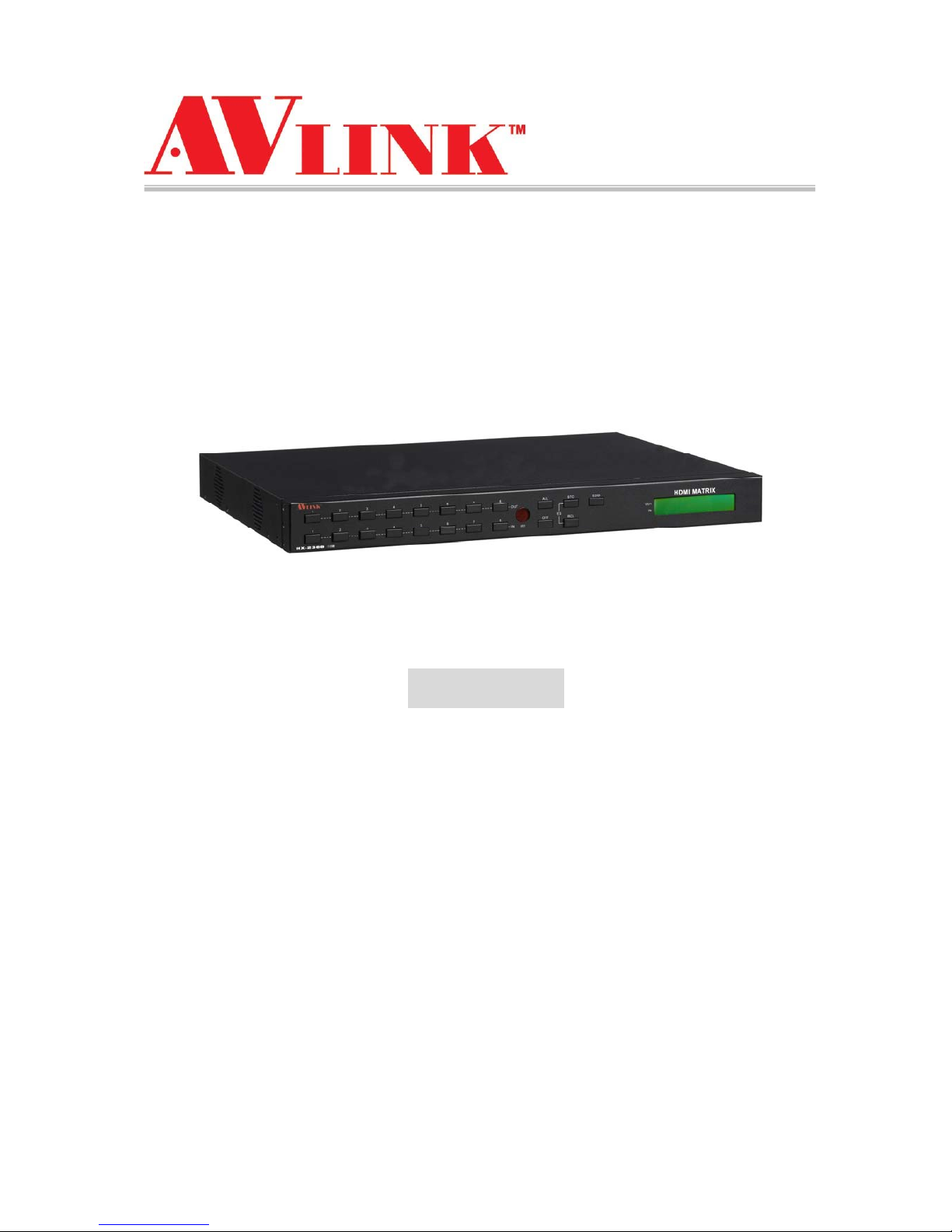
HX-2388 Matrix Switcher is high performance HDMI switching equipment combining with
video and audio. It is used for input/output cross switching of image signals. Through 8
separated HDMI sources, you can also transmit images input separately to each
multi-output equipments, thereby minimizing signal attenuation and ensuring high
definition, integrating high fidelity graphics and audio signal output. Besides HX-2388
Matrix switcher is unlike typical HDMI switchers only communication limited the distance,
through the HDMI-EP devices, you can over long distances to transmit signals.
HX-2388 Matrix Switcher is used mainly in TV broadcasting projects, multi-media
conference halls, and large display projects, TV teaching and command control centers.
It boasts features of power interruption protection during power surge, LCD display and
synchronous and integrate audio/visual switching functions. HX-2388 supports 8 HDMI
Type A or RJ-45 for input and output connectors. Beside it also supports a RS-232 or
LAN communication port enables convenient communication with remote control
equipment to switch the image signals.
Figure 1-1 HX-2388 Matrix Switcher

Matrix Switching System—User Manual
5
1.0.2 Packing
HDMI Matrix Device
RS-232 Communication Connecting Cable
Power Cord
IR BOX
LAN Line
Controller
2 pcs of AAA battery
HDMI Matrix Software CD
User Manual
2 Rack-Mount Bracket
6 Screws (for Brackets)

Matrix Switching System—User Manual
6
2.0 Features
HDMI Standard Compatible
HDCP Compliant
Supports RS-232 / Ethernet control
Supports IR control
Internal universal power supply
1U rack
Available in 4x4, 4x8, 8x4, and 8x8 fixed I/O interfaces.
Built-in Daughter Card (Board) Interfaces (LAN card optional)
Mixed use either HDMI or Cat.X cables for input port and output port connection.
Supports computer video up to 1920*1200
Supports HDTV up to 1080p
EDID management (Copy from OUT port 1)
3.0 Specifications
Function HX-2388
Input Connector 8 x HDMI Type A or RJ-45
Output Connector 8 x HDMI Type A or RJ-45
RS-232 Connector DB9 Female
LAN Connector RJ-45
Select Switch 21
LCD Module 1
Max. Resolution 1080P
Highest TMDS Frequency 225 MHz
HDMI Cable Distance 10 meter (Max.)
Cat.X Cable Distance 60 meter (Max.)
Power 100~240VAC, 50~60Hz, internal
Housing Metal
Weight 2350 g
Dimensions (LxWxH) 440x336x43mm
Matrix Switching System—User Manual
7
4.0 Device Installation
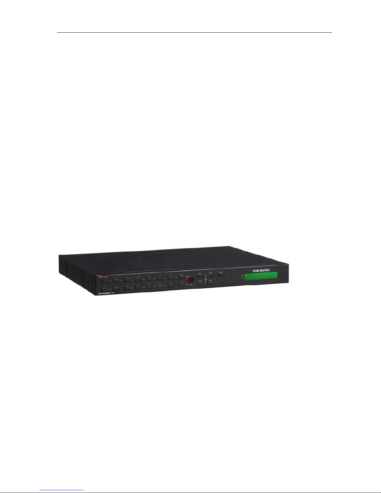
The HDMI Series Matrix device has a black metallic housing. It can be placed on a
sturdy desk directly or installed on a 19-in bracket. See Figure 4-1 below:
Figure 4-1 Mount the HDMI Matrix Device on a Standard Bracket
5.0 Front/Rear Panels
5.0.1 Front Panel
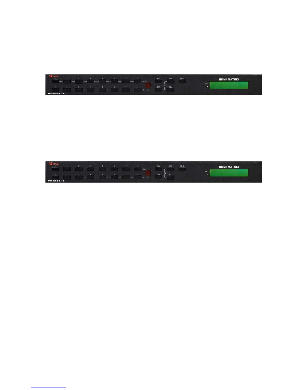
Figure 5-1 HX-2388 Front Panel
The Hx-2388 Matrix Switching System supports up to 8 Output/Input switching keys on
the Front Panel allow you to switch signal quickly.
There are four kinds of module combinations as below:
Operation method No. 1: “Output Channel"+“Input Channel"
Click the Output button then click the Input button to set the combinations.
Operation method No. 2: “STO or RCL"+“Output Channel"
Click the STO or RCL button then click the Output button.
Operation method No. 3: single operation
This example for EDID button, you can click the EDID button directly.
Operation method No. 4: “STO and RCL"+“Input Channel"
Click the STO and RCL button then click the Input button to set the combinations.
OUT1~8 keys (output channel):Indicate the Channel 1~Channel 8 for HDMI signal
output to peripheral display. You can also use these keys to adjust the status or access
the settings
IN1~8 keys (input channel):Indicate the Channel 1~Channel 8 for HDMI signal input.
You can use these keys to switch to the connection of the connected signal source
channels.

Matrix Switching System—User Manual
8
IR1: Infrared receiver.
All: This key allows you to set single input channel to all output channels.
-Press the “All” key.
-Select the one of the IN 1~8 keys.
-The selected IN x key will deliver the signal to all output channels.
-You can also press the “All” key and then the “OFF” key to disable all the
displayed switching settings.
OFF: Disable the entire output channels. Press the one of the OUT x keys that you
want to disable the output channel, then press the OFF key. You can also press the
“All” button and then the “OFF” button to disable all the displayed switching settings.
STO: The “Store Key” saves all current input/output corresponding relations.
-Press the “STO” key firstly. (Supports up to 8 sets of memories, you can select
the memory location through OUT1~OUT8)
-Arrange the Output and Input channel combinations (output channel key 1~8).
-The relation between the Output and Input settings will be saved in the memory
permanently.
RCL: The “Retriever Key” retrieves the saved input/output corresponding relations.
-Press the “RCL” key firstly.
-Then make a random to select one of output channel key 1~8.
-The system will retrieve the saved input/output status and implement current
status switching.
EDID: FIX (fix mode) and TV1 (access the first output channel) selection key.
-FIX mode: The HX-2388 will supply a set of fixed EDID values to support up to
only 1080P high performance TV.
-TV1 mode: The HX-2388 will access the EDID values of high performance TV
that connected to the first output channel, and copy the EDID value to all the
input channels so that the DVD player can support to all the HDTV.
LCD: LCD display shows current HDMI matrix status and operation status.
)Press both the STO and RCL buttons to enter the EQ mode that only takes effective
under RJ-45 Input modules (MX-RJI1_EQ mode). For example as below, make the EQ
value of input channel 2 from 1 to 2. Click the IN button 2 on the front panel again; the
EQ value will become 2 until to the value 8, then the value will return back to 1.
Click again
IN

Matrix Switching System—User Manual
9
5.0.2 Rear Panel
Figure 5-2 HX-2388 Rear Panel
The HX-2388 supports up to 8 input/output connectors (HDMI Type A or RJ-45) on the
rear panel, each female terminals form the signal input/output connectors. The HX-2388
signal input/output terminal channels are numbered from right to left as OUT1~4 / IN1~8
/ OUT5~8 channels. The input terminal channels supply you to connect to different
equipment including DVD players and graphics workstations. The output terminals can
be connected to projectors, video recorders, displays and multiplexes and so on.
Power Port: The Power Port is applicable for 100~240VAC, 50~60Hz connected to the
outlet of power source.
Power Switch: To switch power ON or OFF the HDMI matrix device.
RS-232: Use the RS-232 connection cable to connect the computer serial port (COM1
or COM2) to the RS232 communication port of the HDMI matrix device. The computer
can then be used to control the HDMI matrix after installation of application software.
The RS-232 port is a 9-pin female connector.
IR2: Connect to the IR BOX
.
Switcher:
-Pin1: Switch between RS-232 port and LAN port connection.
-Pin2: This Pin allows you to reset the IP value to 192.168.0.3. The steps are as
below:
a. Please adjust the pin2 down and re-start HX-2388.
b. After the HX-2388 re-starts about 10sec, shut down your equipment.
c. Adjust the pin2 up, then power on HX-2388 again.
d. The IP address will be restored to the default value: 192.168.0.3
-Pin3: No definition.
Pin # UP DOWN
1 LAN RS-232
2 NORMAL IP DEFAULT
3 NC NC
Matrix Switching System—User Manual
10
LAN Port: Use the RJ-45 connection cable to connect the Internet and the HDMI
matrix device. The entire PC at the same network can control the HDMI matrix device
through the LAN port.
IN1~8: Depend on the built-in modules, HDMI matrix device Input Channels are
connected to the DVDs or HDMI-LP, for more information please refers to Appendix A.
OUT1~8: Depend on the built-in modules, HDMI matrix device Output Channels are
connected to the HDTVs or HDMI-RP,for more information please refers to Appendix
A.
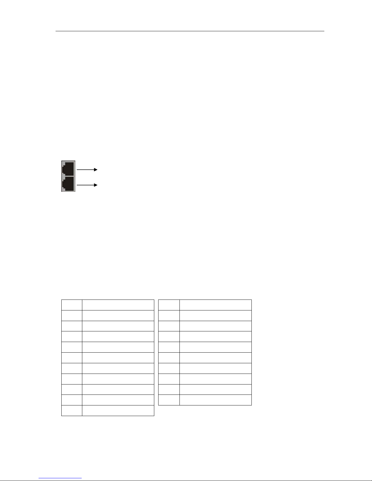
When using the extender port modules, up port is for DDC function, down port is for
VIDEO function.
)For RJ-45 Connector daughter board modules equipment, the connection has a
collocation with HDMI-EP; please refer to the Appendix A for more information.
Daughter board modules:
MX-HDI1 HDMI Connector input
MX-HDO1 HDMI Connector output
MX-RJI1 RJ-45 Connector input (for extender port)
MX-RJO1 RJ-45 Connector output (for extender port)
HDMI Type A Connector pin definition:
Pin # Signal Pin # Signal
1 TMDS Data2+ 11 TMDS Clock Shield
2 TMDS Data2 Shield 12 TMDS Clock-
3 TMDS Data2- 13 NC
4 TMDS Data1+ 14 NC
5 TMDS Data1 Shield 15 DDC-SCL
6 TMDS Data1- 16 DDC-SDA
7 TMDS Data0+ 17 DDC-Ground
8 TMDS Data0 Shield 18 +5V Power
9 TMDS Data0-
19 Hot Plug Detect
10 TMDS Clock+
DDC function
VIDEO function

Matrix Switching System—User Manual
11
6.0 HDMI Matrix and Peripherals Connection
Figure 6-1 HDMI Matrix System Connections
)Use the HDMI-EP devices to extend the connection, please refers to the Appendix A.

Matrix Switching System—User Manual
12
6.0.1 Input/Output Connections
Use the HDMI connecting cable to connect the Input/Output serial port (No.1 ~ No.8) to
the HDMI port of the DVD Player/HDTV or HDMI-EP.
Figure 6-2 Input Connections
Figure 6-3 Output Connections

Matrix Switching System—User Manual
13
6.0.2 HDMI Matrix / Control Computer Connection
Use the RS-232 connecting cable to connect the computer serial port (COM1 or COM2)
to the RS-232 communication port of the HDMI matrix device. The computer can then be
used to control the HDMI matrix after installation of application software. Aside from
using the front panel keys for switching operation, you are also permitted to use the
RS-232 connection port for remote operation.
Figure 6-4 (a) RS-232 and Control PC connection
HX-2388 also supports a LAN port allows you to control the equipment device through
PC Browser.
Figure 6-4 (b) LAN port and Control PC Connection
Matrix Switching System—User Manual
14
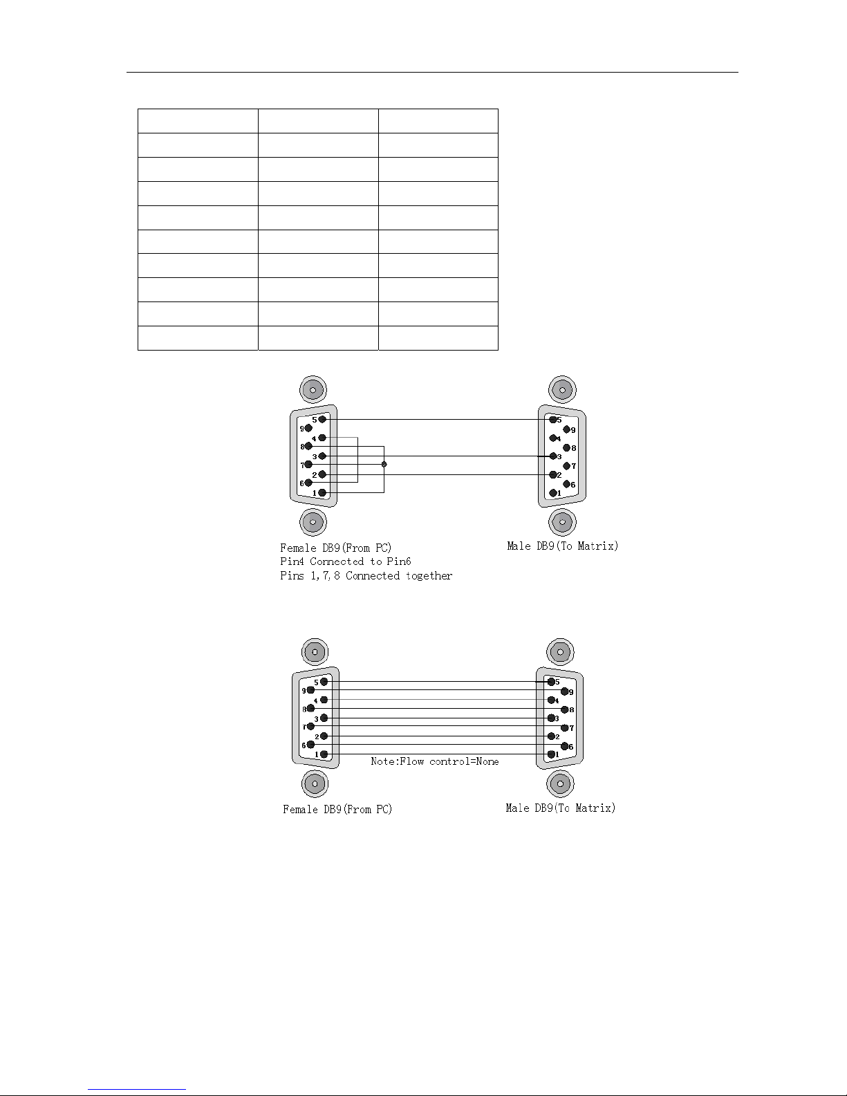
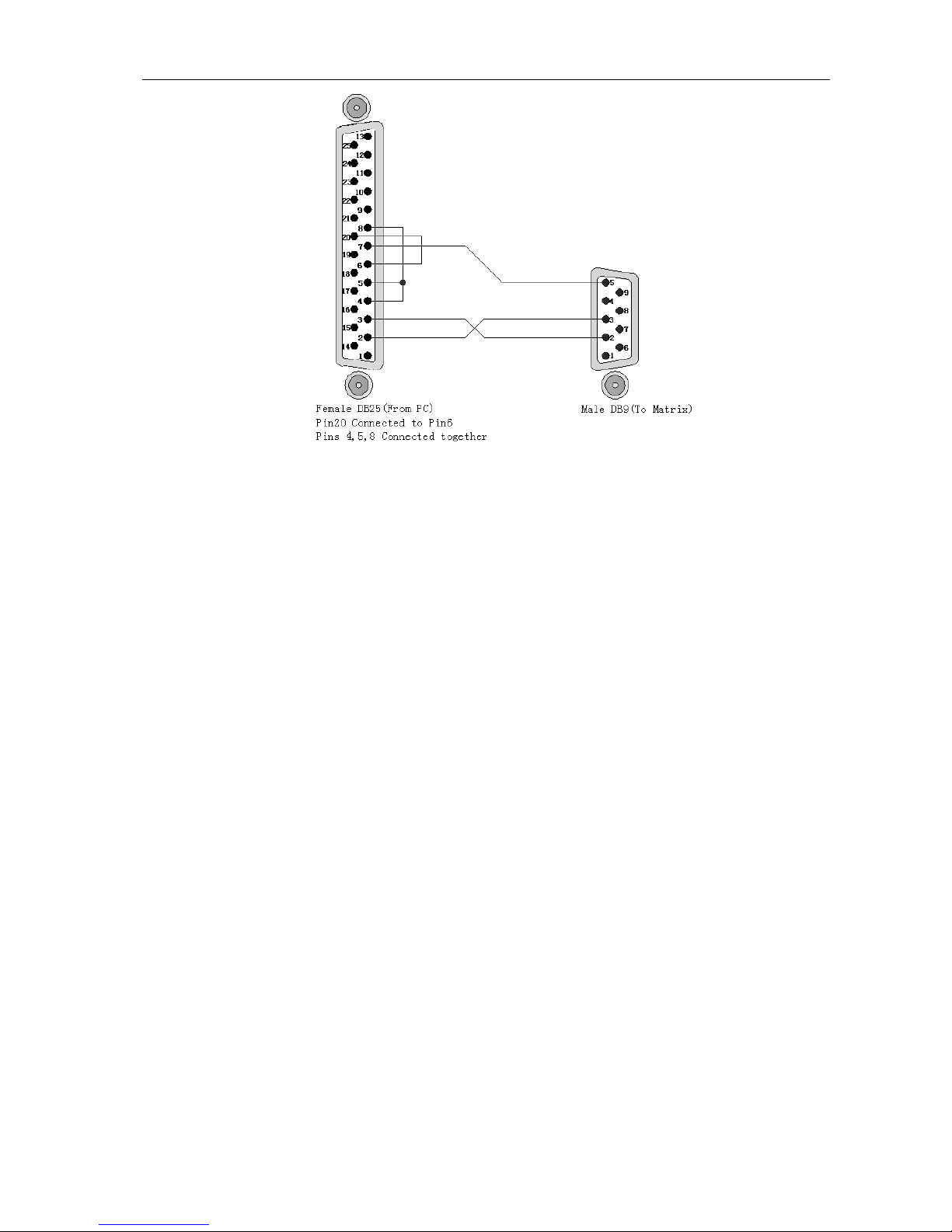
The RS-232 Leg functions are described as below:
Pin No. Leg Description
1 N/u Null
2 TXD Send
3 RXD Receive
4 N/u Null
5 GND Ground
6 N/u Null
7 N/u Null
8 N/u Null
9 N/u Null
Figure 6-5
Figure 6-5 (a)
Matrix Switching System—User Manual
15
Figure 6-5 (b)
)The Matrix RS-232 port is defined as DCE.

Matrix Switching System—User Manual
16
6.0.3 IR2 Connection
The HDMI matrix provides you an IR BOX for more convenient to react to the controller.
Please connect the IR BOX to the IR2 port that is on the rear panel.
Figure 6-6 IR Connection
6.0.4 Power connection
Use the included power cord to connect from the power port on the rear panel of HDMI
matrix device to the outlet.
Figure 6-7 Power Connection

Matrix Switching System—User Manual
17
7.0 Matrix Application Software
7.0.1 Software Introduction
The 《AV Matrix》Matrix control software applies to different input/output matrixes.
7.0.1.1 Software Description
The《AV Matrix》matrix testing software is an application tool developed for matrix testing
and application. The software operation environment is as follows:
Window98/2000/7/NT/XP/Vista/ operating systems
32M internal memory or above
10M hard disk space or above
CD-ROM
At least one serial communication port
7.0.1.2 Software Activation
First, you must power off both the HDMI matrix and the computer. Then, connect the
matrix RS-232 port to the PC RS-232 port with the bundled communication cable. (Refer
to the previous section “HDMI Matrix and Control Computer Connection”.
Power on the HDMI matrix and the computer:
Activate the AV Matrix.exe on the bundled CD-ROM in the control computer to enter the
software configuration screen.
Matrix Switching System—User Manual
18
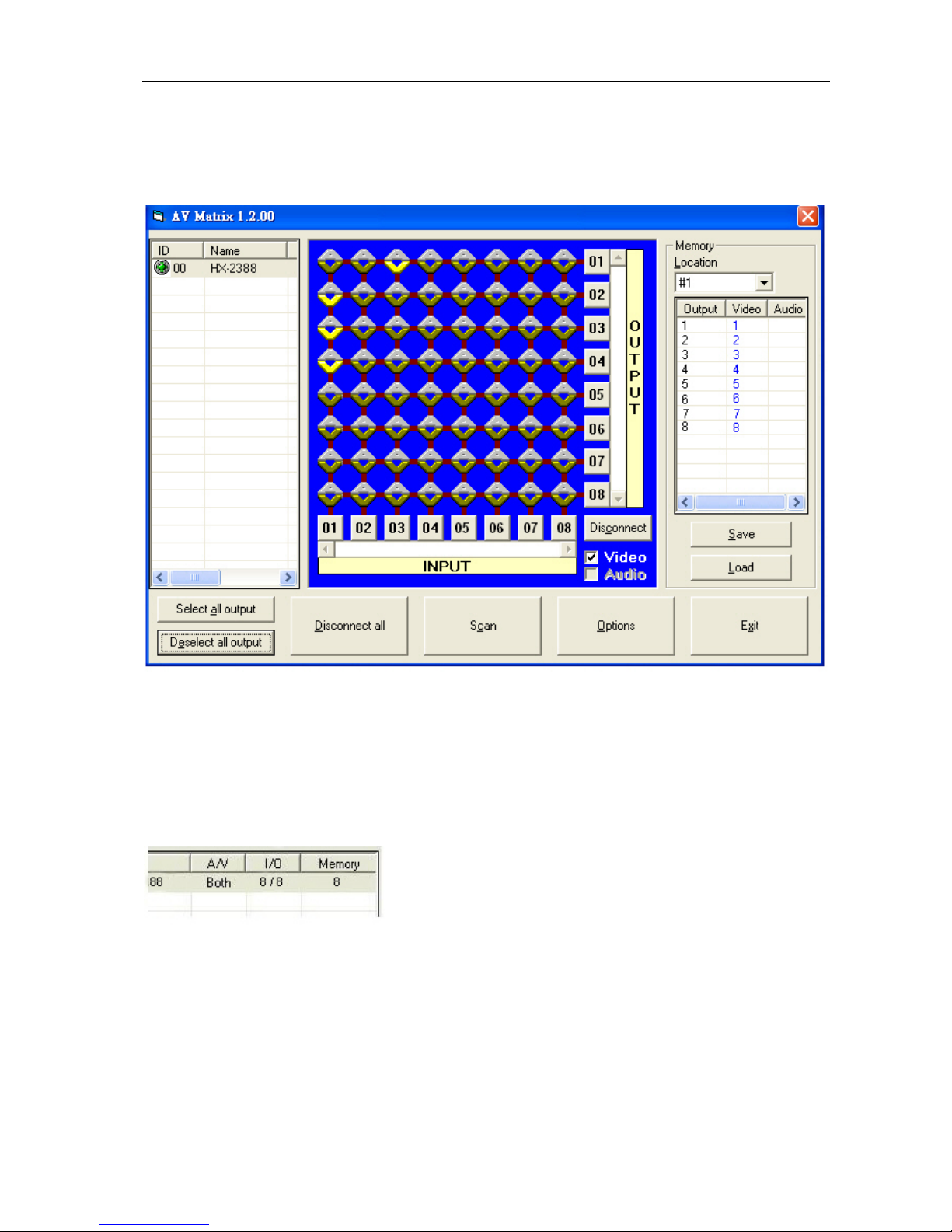
7.0.2 RS-232 Software Configuration
The software controls signal connection between the corresponding input port and
output port as required. The RS-232 main configuration screen is as below:
Figure 7-1 RS-232 Software Configuration Screen
)HX-2388 is HDMI switching equipment; please select the Video check box before you
begin to operate the software.
)HX-2388 Device ID is fixed at 0.
Scroll on the left area of the main screen to view contents as shown below.
Matrix Switching System—User Manual
19
7.0.2.1 RS-232 Main Operation Interface
Refer to the main configuration screen as above, the marked blue area shows crossing
matrix of output ports 01-08 and input ports 01-08. For the basic operation is described
as below:
Examples for Selecting Matrix Switching Functions:
Example: Now there is an HX-2388 matrix having all the input/output ports properly
connected to the equipment. If you want to set channel 1 input to channel 2, 3 and 4
output; channel 3 inputs to channel 1 output. There are 2 ways to implement the
switching. Please follow the ways and steps to finish the switching functions:
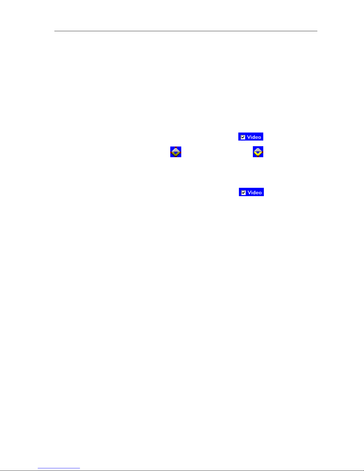
First way: Make sure you have selected “Video” check box ( ). Directly click on
the corresponding icons on the matrix to transform them into to complete the
switching operation.
Second way:
Step 1: Make sure you have selected “Video” check box ( ).
Step 2: First select the “Output” number keys 02, 03 and 04 to the right of the blue
configuration area, and select the “Input” number key 01 to the bottom.
Then, press consecutively the previously selected “Output” number keys 02,
03 and 04 (or you can press the “Deselect all output” key). This way, you
have selected “Input” 01 and “Output” 02, 03 and 04 switching.
Step 3: First select the “Output” number key 01 to the right of the blue configuration
area, and select the “Input” number key 03 to the bottom. Then, press the
previously selected “Output” number key 01 (or you can press the
“Deselect all output” key). This way, you have selected Input 03 and
Output 01 switching.
Upon completion of the above 3 steps, you have actually completed the switching
operation of having channel 1 input to channel 2, 3 and 4 output while at the same time
successfully switched from channel 3 input to channel 1 output.
The main configuration screen also shows you some function buttons to easy operation:
Disconnect: To disable the connections.After you had configured the connection
between input and output ports, you can click this button to disable the connections.
Select all output: Click this button to select all output ports including output 01~08.
Deselect all output: Click this button to cancel presently selected output ports.After you
had configured a connected combination, please click this button firstly for next settings.
Disconnect all: To stop all the connections.
Scan: To search the device controlled by the RS-232 Software Configuration. When the
device name located on the left of the main configuration screen is empty, you can click
Table of contents
Other AVLink Matrix Switcher manuals

AVLink
AVLink HX-2544 User manual

AVLink
AVLink YX-1042 User manual

AVLink
AVLink HX-331616 User manual

AVLink
AVLink 128.850UK User manual

AVLink
AVLink CX-2044 User manual

AVLink
AVLink HX-2344 User manual

AVLink
AVLink SX-2088 User manual

AVLink
AVLink SD-1 User manual

AVLink
AVLink MX-3UB User manual

AVLink
AVLink BX-3044 User manual


