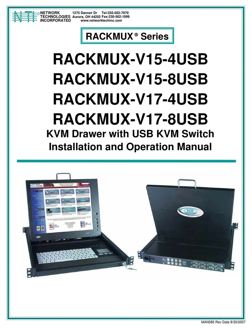
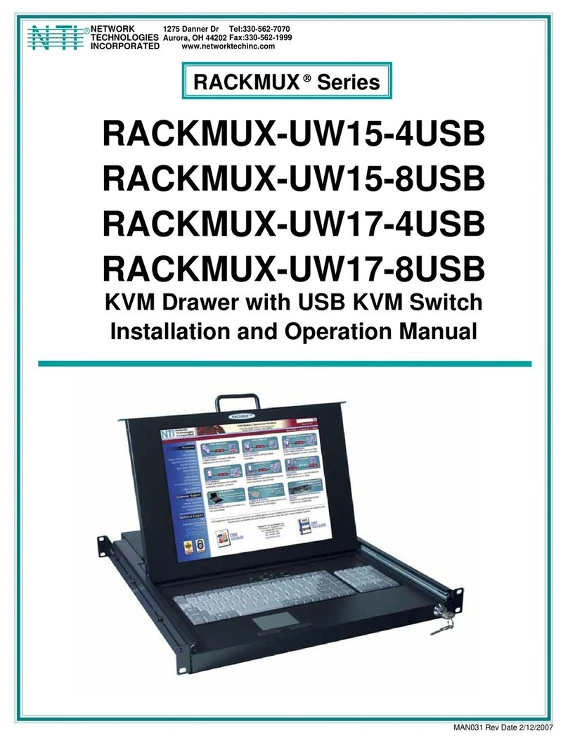
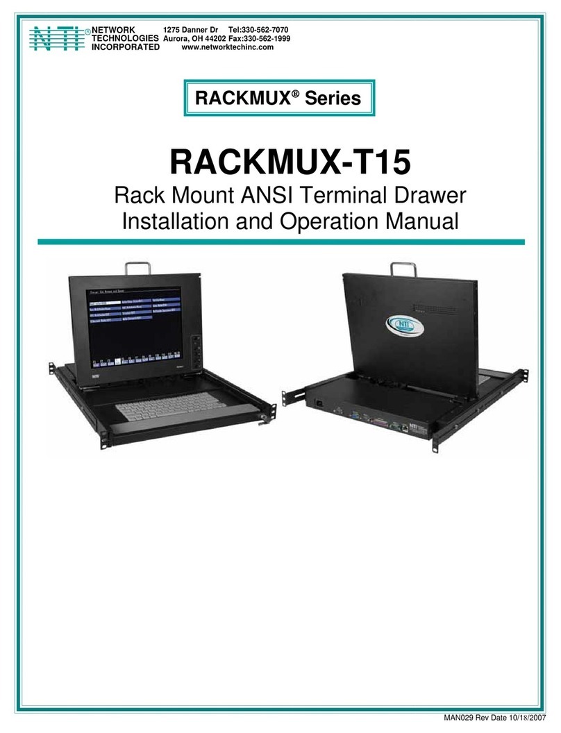
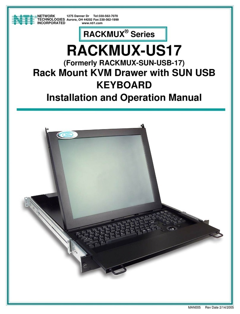
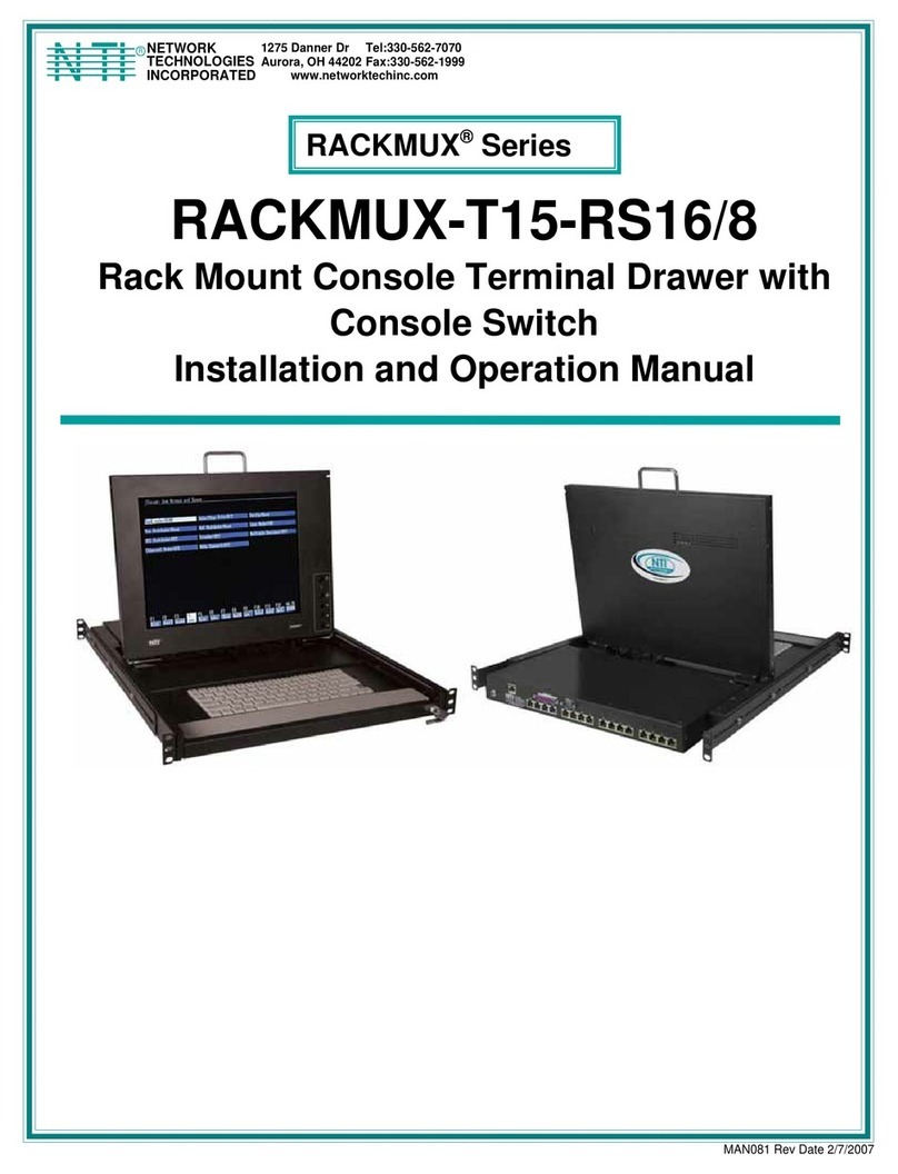
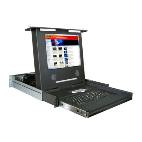
Network Technologies RACKMUX-V15 User manual

MAN047 Rev Date 5/9/2013
RACKMUX-V15/17/20
RACKMUX-D17
Rackmount Drawer with Keyboard, LCD
Monitor and Mouse
Installation and Operation Manual
RACKMUX®Series
RACKMUX-V17-
N
(Front and Rear View)

i
TRADEMARK
RACKMUX is a registered trademark of Network Technologies Inc in the U.S. and other countries.
COPYRIGHT
Copyright © 2007, 2013 by Network Technologies Inc. All rights reserved. No part of this publication may be reproduced, stored
in a retrieval system, or transmitted, in any form or by any means, electronic, mechanical, photocopying, recording, or otherwise,
without the prior written consent of Network Technologies Inc, 1275 Danner Drive, Aurora, Ohio 44202.
CHANGES
The material in this guide is for information only and is subject to change without notice. Network Technologies Inc reserves the
right to make changes in the product design without reservation and without notification to its users.
Typographic Conventions
The following table describes the typographic changes used in this instruction.
Typeface Meaning Example
AAaaBBaaCCcc123 On-screen computer output C:>
AAaaBBaaCCcc123 What you type, contrasted with on-screen
computer output; keyboard keys to press C:> L
Press the Fn key

ii
TABLE OF CONTENTS
Introduction......................................................................................................................................................................1
Features and Functions...................................................................................................................................................2
Installation .......................................................................................................................................................................3
Rack Mounting Instructions .........................................................................................................................................3
Optional Telco 2-Post Mounting ...............................................................................................................................4
Connect to a CPU........................................................................................................................................................4
Connect Extra Device..................................................................................................................................................6
Remote PC Connection...............................................................................................................................................6
Manual IP Address Change......................................................................................................................................8
Software IP Address Change ...................................................................................................................................9
Connect Power..........................................................................................................................................................10
Power Up...................................................................................................................................................................10
Display Functions..........................................................................................................................................................11
Standard Controls......................................................................................................................................................11
OSD Control Menu- 15 and 17 Inch VGA models (-V15/-V17).................................................................................11
OSD Main Menu .....................................................................................................................................................11
Brightness/Contrast Menu......................................................................................................................................12
Color Menu .............................................................................................................................................................12
Position Menu.........................................................................................................................................................12
Setup Menu.............................................................................................................................................................13
OSD Control Menu-DVI Model (-D17).......................................................................................................................13
OSD Main Menu .....................................................................................................................................................13
Brightness/Contrast Menu......................................................................................................................................14
Setup Menu.............................................................................................................................................................14
OSD Control Menu- 20 Inch VGA Model (-V20)........................................................................................................15
OSD Main Menu .....................................................................................................................................................15
OSD Control Menu- 17 Inch Hi-Resolution Model (-HR)...........................................................................................17
OSD Main Menu .....................................................................................................................................................17
Keyboard Functions ......................................................................................................................................................19
Function Key Operation..........................................................................................................................................19
Number Pad............................................................................................................................................................20
Other Uses of the Function Key..............................................................................................................................21
Numeric Keypad Option.............................................................................................................................................22
PS/2-USB Keyboard/Mouse Mode............................................................................................................................23
SAFETY.........................................................................................................................................................................24
Rackmux-KVM Drawer Standard Specifications...........................................................................................................25
General Specs...........................................................................................................................................................25
LCD – 15” ..................................................................................................................................................................25
LCD – 17” ..................................................................................................................................................................25
LCD – 20.1” ...............................................................................................................................................................26
Display Controller: VGA (-15,-17 & -20)....................................................................................................................26
Display Controller: DVI (-17)......................................................................................................................................26
OSD Control Board....................................................................................................................................................26
Keyboard....................................................................................................................................................................26
Touchpad...................................................................................................................................................................27
Troubleshooting.............................................................................................................................................................28
Index..............................................................................................................................................................................28
Warranty Information.....................................................................................................................................................28

iii
TABLE OF FIGURES
Figure 1- Mount RACKMUX to a standard rack.................................................................................................................................3
Figure 2- Position RACKMUX with clearance to open.......................................................................................................................3
Figure 3- Mount to Telco post with optional mounting brackets.........................................................................................................4
Figure 4- Connect a PS/2 CPU..........................................................................................................................................................4
Figure 5- Connect a USB CPU..........................................................................................................................................................5
Figure 6- Cables used for RACKMUX with DVI video support...........................................................................................................5
Figure 7- Connect a USB 1.1 device to the front (optional)................................................................................................................6
Figure 8- Connect Remote PC to KVM on IP at "LAN" port...............................................................................................................6
Figure 9- Remote Console Preview...................................................................................................................................................7
Figure 10- Login Screen for KVM on IP.............................................................................................................................................8
Figure 11- Network Configuration screen ..........................................................................................................................................8
Figure 12- Connect the power cord .................................................................................................................................................10
Figure 13- OSD Controls .................................................................................................................................................................11
Figure 14- Main Menu for 20-inch LCD Monitor...............................................................................................................................15
Figure 15- US(English) Keyboard Layout ........................................................................................................................................19
Figure 16- Keyboard LED Indications..............................................................................................................................................19
Figure 17- Keys of the Number Pad ................................................................................................................................................21
Figure 18- Additional multi-function keys.........................................................................................................................................21
Figure 19- U.S. (English) keyboard with numeric keypad................................................................................................................22
Figure 20- U.K. (English) keyboard with numeric keypad................................................................................................................22
Figure 21- German keyboard with numeric keypad .........................................................................................................................23

NTI RACKMUX-V15/17/20 RACKMOUNT LCD MONITOR WITH KEYBOARD AND MOUSE
1
INTRODUCTION
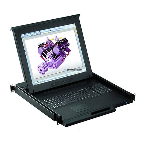
The RACKMUX-V15/17/20 Drawer (RACKMUX) consists of a Keyboard, Touchpad, and LCD monitor integrated into a
1RU rack-mountable drawer with wrist pads. When access to a server rack is needed, the drawer can be pulled out and the
display lifted up like a notebook computer, revealing the keyboard and mouse. When the drawer is not in use, the display can be
folded forward and down so the 1RU drawer can be pushed into the cabinet easily and smoothly, helping to organize and
streamline busy server rooms. The NTI RACKMUX product line offers a range of KVM Drawer solutions ideal for rack and server
management applications, which will ensure reliability and serviceability.
The RACKMUX will switch between USB and PS/2 standards for versatile connection to a CPU. The forward-folding LCD
monitor is offered in either 15”, 17”, or 20” (designated in the product name as -15 ,-17 or -20) and the video format can be either
VGA or single-link DVI (designated by –V or –D: example RACKMUX-V15). For user input, the drawer offers a notebook-style
keyboard, wrist-pad, and a three-button touchpad. The keyboard and mouse can be connected using USB and PS/2 cables. USB
and PS/2 interfaces will remain active at all times and the keyboard and mouse can be switched, at any time, to use either one.
The RACKMUX-V15/-V17/-V20 also provides a front panel USB 1.1 port for the connection of an external USB device (such as a
flash drive).
The keyboard and mouse interface is compatible with Windows platform CPUs. This multiple interface capability reduces
equipment costs by ensuring that a single console is compatible with various PC/server input devices.
Installing the RACKMUX into any server environment will offer:
•A space saving 1RU design, easily mountable in any 19” cabinet/rack
•A forward-folding 15”,17”, or 20” TFT LCD with built-in OSD menu for screen adjustments
•Auto shut-OFF switch: Turns OFF the power to the monitor when the LCD is in a folded-closed position.
•Built-in 83-key (US) or 84-key (Europe) keyboard with wrist pad
•Standard 3-button mouse touchpad
•Support for PS2 and USB connections for the keyboard and mouse.
•Support for VGA (15”, 17”or 20” model) or single-link DVI signals (17” model only)
•Front-access USB port for easy accessory USB 1.1 device connection
•An internal cable arm for proper cable management when sliding the drawer open and closed
•Added security with a drawer lock to prevent unwanted access
•Locking rails to prevent movement of the drawer when fully extended
•Built-in universal (100-240VAC) low power consumption power supply
•Multi-language support including: US(English), UK(English), German, French, Italian, Spanish
Materials Included with this kit:
9NTI RACKMUX-V15/17/20 Drawer with VGA Video support
~or~
9NTI RACKMUX-D17 Drawer with DVI Video support
92 Keys for Lock
92 Rear Mounting Brackets w/nuts
98 #10-32x3/4” screws and cage nuts for mounting to a rack
9IEC Power Cord- country specific
9CD with a pdf file of this owner's manual and the drawer installation manual
9USB-AB-2M 2 meter USB Type A male-to-USB Type B male cable
9VVKINT-6-MM 6 foot PS/2 mouse and keyboard cable (not included with KVM on IP model)
9VEXT-THN-6-MM 6 foot VGA video cable (models with VGA Video support only)
9DVI-DS-2M-MM 2 meter DVI video cable (model with DVI Video support only)
95 foot RJ45-to-RJ45 CAT5 patch cable (model with KVM on IP only)
9CAT5-CO-MF Crossover Adapter (model with KVM on IP only)
Alternative Cables (not supplied):(available in 3,6,10 and 15 foot lengths)
VKMEXT-xx-MM for VGA Monitor and PS2 Keyboard and Mouse input
USBVEXT-xx-MM for VGA Monitor and USB Keyboard/Mouse input and USB device support
where:
xx is the length of the cable in feet
MM indicates male-to-male connector
Option:
•Trackball option- for a RACKMUX with a trackball instead of a touchpad- add “T” to the part number (i.e. RACKMUX-V17-T)
•Numeric keypad option- for a separate 17-key numeric keypad, add “-N” to the part number (i.e. RACKMUX-V17-N)
•KVM on IP option- for a RACKMUX with a KVM on IP unit for remote access, add “-IP” to the part number
(i.e. RACKMUX-V17-N-IP)
•Hi-Resolution Monitor- for a 17” RACKMUX with hi-resolution monitor (1920 x 1200)- add “HR” to the part number (i.e.
RACKMUX-V17HR (available on 17” models only))
Cables can be purchased from Network Technologies Inc by calling
(800) 742-8324 (800-RGB-TECH) in the US and Canada or (330) 562-
7070 (worldwide).

NTI RACKMUX-V15/17/20 RACKMOUNT LCD MONITOR WITH KEYBOARD AND MOUSE
2
FEATURES AND FUNCTIONS
1. Power Button- press to turn the LCD monitor ON and OFF
2. Power LED- Indicates operation status
Green = Power-ON, Video Input Signal OK
Red = Suspend / Stand-by, or no Video Input Signal
3. Menu Button- press to turn ON the OSD menu
4. Up Arrow Button- press to move the cursor in the OSD menu up
5. Down Arrow Button- press to move the cursor in the OSD menu down
6. Select Button- press to select a menu item (when OSD menu is ON) or press to auto adjust the video quality (when OSD
menu is OFF)
7. NumLock LED- illuminates when the number lock is ON
8. CapsLock LED- illuminates when CapsLock is ON.
9. Scroll Lock LED- illuminates when the Scroll Lock keyboard feature is ON.
10. Fn LED- illuminates when Function Features (page 19) are enabled.
11. USB LED- illuminates when RACKMUX drawer is in USB mode
12. PS/2 LED- illuminates when RACKMUX drawer is in PS/2 mode
13. 3-button mouse- for controlling mouse movements on the monitor and controlling the computer
14. Keylock- to prevent unauthorized use of the RACKMUX
15. Auto Shut-OFF- switch automatically shuts OFF the LCD display when the monitor is folded down
16. keyboard- for manual data entry and computer control
17. USB Port- USB Type A female- for connection of any USB 1.1 compatible device (such as a flashdrive, printer, etc)
18. LCD Display- for viewing the video signal from the connected CPU
19. IEC Connector- for attachment of the IEC power cord to power the RACKMUX drawer
20. Switch- for powering ON and OFF the RACKMUX drawer
21. Video In- 21A. 15HD Female- for connection of the VGA video cable from the CPU (only in models that support VGA video)
21B. DVI-D Female- for connection of a DVI-D video cable from the CPU (only in models that support DVI)
22. USB- USB Type B female- for connection of the USB cable from a USB CPU
23. Keyboard Connector- purple 6 pin miniDIN female- for connection of the PS/2 keyboard cable from a PS/2 CPU
24. Mouse Connector- green 6 pin miniDIN female- for connection of the PS/2 mouse cable from a PS/2 CPU
Front View
RACKMUX-V17
Rear View
RACKMUX-V17
24
18
16 14
15 1A
9
8
7
Fn
10
17
11 12
PS/2
13
1
2
3
4
5
6
19 22
2320
(RACKMUX-D17)(RACKMUX-V17)
21A 21B
- or -

NTI RACKMUX-V15/17/20 RACKMOUNT LCD MONITOR WITH KEYBOARD AND MOUSE
3
INSTALLATION
The following rack mounting instruction does not apply to RACKMUX units with 20 inch LCD monitors. For mounting instruction
applicable to models with 20 inch LCD monitors, see “Installation Manual For Drawer with 20 Inch LCD Monitor” on the CD.
Rack Mounting Instructions
The RACKMUX was designed to be mounted to a rack and includes mounting flanges to make attachment easy.
1. Determine the mounting height in the rack for the drawer. It should be a height comfortable to use the keyboard and see the
LCD display. Mark holes in each of the 4 corner cabinet rails at points all level with each other.
2. Secure the rear brackets to the rear rack cabinet rails. Apply the top screws (supplied) for each bracket to the holes marked in
step 1.
3. Lift the keyboard into position and line the studs on the left and right sides up with the slotted openings in the rear bracket.
Apply the nuts (supplied) to the studs but do not tighten the nuts yet.
FYI: There are 4 mounting studs provided on each side of the RACKMUX. Depending on the depth of the rack and
distance apart of the cabinet rails, the position of the rear bracket may make all 4 studs available for use. In this case,
apply the 2 nuts to the studs furthest apart from each other on each side.
4.Slide the drawer in until the top holes in the front bracket flanges line up with the holes marked in step 1. Secure the front
brackets on the drawer to the front cabinet rails with two screws per bracket. Be sure to tighten the screws securely. Then
tighten the nuts applied in step 3.
5.Apply one more screw to each of the rear brackets to finish.
Figure 1- Mount RACKMUX to a standard rack
Note: To provide sufficient room for the LCD monitor to be opened to a proper viewing angle (a minimum 90 degree
position from the keyboard), ensure that all devices mounted above the RACKMUX extend no more than 1.75” from the
rack frame. (See Fig. 2)
Figure 2- Position RACKMUX with clearance to open
Apply nuts (supplied) to studs and
secure rear brackets to drawer.
Front bracket
flange on drawer
Rear bracket
flange
Drawer
Front Cabinet
Rail Rear Cabinet
Rail
Rear bracket overlapping
drawer (Rear edge
of drawer)
Stud on drawer
Secure bracket
to rail using two
screws and nut
s
(supplied)
Secure bracket
to rail using two
screws and nuts
(supplied)
Side View of RACKMUX
"X" must be
less than 1.75"
for LCD to open
to full 90
X
90
Server mounted
above RACKMUX
in the same rack

NTI RACKMUX-V15/17/20 RACKMOUNT LCD MONITOR WITH KEYBOARD AND MOUSE
4
Optional Telco 2-Post Mounting
If the Telco 2-post mounting bracket kit (NTI# RL-T15-TEL)is to be used, secure the short and long brackets to each side of the
drawer as shown in Fig. 2. Apply 2 nuts (supplied) per bracket to secure the brackets to the drawer. Apply two #10-32x3/4”
screws (supplied) per bracket to the post at the desired height. Slots are provided in the brackets to make minor depth
adjustments easy. Be sure to properly tighten all nuts and screws before using the drawer.
Figure 3- Mount to Telco post with optional mounting brackets
Connect to a CPU
The RACKMUX may be connected to either a PS/2 or a USB CPU with a VGA video port. To connect to a PS/2 CPU, use a
VEXT-6-MM cable and VVKINT-6-MM cable as shown in Figure 4. To connect to a USB CPU, use the VEXT-6-MM and USB-
AB-2M cables as shown in Figure 5.
Figure 4- Connect a PS/2 CPU

NTI RACKMUX-V15/17/20 RACKMOUNT LCD MONITOR WITH KEYBOARD AND MOUSE
5
Figure 5- Connect a USB CPU
When connecting a CPU with DVI support to the single-link DVI port of the RACKMUX, use a DVI-DS-2M-MM (supplied) for the
DVI video signal, a USB-AB-2M (supplied) for the USB connection, and if using PS/2 keyboard and mouse connections,
connect a VVKINT-6-MM cable (supplied) between the CPU and RACKMUX.
Figure 6- Cables used for RACKMUX with DVI video support
USB-B - Male
USB-A - Male
DVI-D-Male
DVI-D-Male
USB-AB-2M
(supplied)
DVI-DS-2M-MM
(supplied)
6 miniDIN Male VVKINT-6-MM
(supplied)
(3,10, 15,25, 35, and 50 foot
lengths also available)
6 miniDIN-Male
Purple-Keyboard
6 miniDIN-Male
Green-Mouse 6 miniDIN-Male
Green-Mouse
6 miniDIN-Male
Purple-Keyboard
DVI-D-Male
USB Type B
Male
USB Type A
Male
(.5, 1, 3, and 5 meter cables also available)

NTI RACKMUX-V15/17/20 RACKMOUNT LCD MONITOR WITH KEYBOARD AND MOUSE
6
Connect Extra Device
On the front of the RACKMUX is an additional USB Type A port to be used, if desired, for an extra accessory. Any low or full
speed USB device may be connected to this port to be used. This port is fully compliant with USB standard 1.1.
Note: In order for the optional USB device port to be usable, the USB port on the rear of the RACKMUX must be
connected to a USB enabled CPU (a 2 meter USB cable is supplied).
Note: If a USB keyboard or mouse is connected, operation of the RACKMUX keyboard or mouse may cause
unpredictable results. Do not try to use both mice or both keyboards at the same time.
Figure 7- Connect a USB 1.1 device to the front (optional)
Note: If a USB 2.0 device is connected to the optional USB device port, it will operate at USB 1.1 speed.
Remote PC Connection
The RACKMUX with KVM on IP unit includes a port for Ethernet connection to your LAN. If you have purchased the RACKMUX
with KVM on IP (i.e. RACKMUX-V17-N-IP), follow these instructions to make your connections for remote access.
1. Make a connection between an available RJ45 Ethernet port on a PC and the ”LAN”port on the RACKMUX. A five foot patch
cable and crossover adapter have been included for this purpose.
Figure 8- Connect Remote PC to KVM on IP at "LAN" port
CAMERA
PRINTER SCANNER
Connect optional USB 1.1 or 2.0 device
FLASH DRIVE
FRONT VIEW OF RACKMUX-V17

NTI RACKMUX-V15/17/20 RACKMOUNT LCD MONITOR WITH KEYBOARD AND MOUSE
7
2. The default IP address of the KVM on IP is 192.168.0.70.
If 192.168.70 is not compatible with your subnet, you may want to change the IP address of the KVM on IP to one that is. To
change the IP address of the KVM on IP, either follow the “Manual IP Address Change” or the “Software IP Address Change”
methods described on page 8 and page 9 .
3. Enter the IP address in the browser URL address block. .
4. Log into the KVM on IP. Enter the default user name and password for the KVM on IP:
Username = super
Password = pass
5. With a proper login, a window “Remote Console Preview”will be displayed. Click on the link “Click to open”.
Figure 9- Remote Console Preview
A connection will be made between your remote PC and the RACKMUX Drawer. The screen that opens is a virtual PC that
enables you to control the RACKMUX just as if you were actually at the keyboard of the RACKMUX. Using the mouse, switch
between the virtual PC and your actual computer interface.
If the remote connection is closed while in the KVM on IP menu, to re-open the connection click on “Remote Control”, then
“KVM Console”.
Note: There are more features available in the menu for the KVM on IP, but their use or configuration is not necessary in
the operation of the RACKMUX-V17-N-IP.

NTI RACKMUX-V15/17/20 RACKMOUNT LCD MONITOR WITH KEYBOARD AND MOUSE
8
Manual IP Address Change
1. The Ethernet port on the PC must be configured with an IP of 192.168.0.xxx where xxx is any number except 70.
(You may need to configure the Ethernet port network information on the PC such that it can connect to the KVM on IP device
in the RACKMUX.)
Note: Connecting to the KVM on IP requires the installation of the Java Runtime Environment. A link to the web page
from which it can be downloaded and installed is provided on the Product Manual CD in addition to a Windows
compatible copy of the application itself.
2. Open a browser window on the PC. Type “192.168.0.70” into the URL address block. A login prompt will appear.
Figure 10- Login Screen for KVM on IP
3. Enter the default user name and password for the KVM on IP:
Username = super
Password = pass
4. The KVM on IP will open the main menu. To change the network configuration, go to “Device Settings”, and then “Network” to
open the network configuration settings page for the KVM on IP.
Figure 11- Network Configuration screen

NTI RACKMUX-V15/17/20 RACKMOUNT LCD MONITOR WITH KEYBOARD AND MOUSE
9
5. Enter the desired network connection settings (IP address, subnet mask, gateway) as compatible with your network.
Make note of these settings in case you need them later.
6. With the settings updated, press “Apply”to implement the changes in the KVM on IP. Your browser connection to the KVM
on IP is no longer valid.
7. To restore connection to the KVM on IP, change the IP address on the PC back to an address compatible with your network
and now also compatible with the KVM on IP.
Having configured the KVM on IP to be compatible with your network, you can now make a direct cable connection (crossover
adapter not needed) to your network through a router or switch.
Software IP Address Change
1. Locate the program psetup.exe on the CD this manual is found on, in the “KVMonIP” subdirectory. Double-click on it.
2. Click Refresh Devices. The program will detect any network connected IP-KVM devices and display them by their MAC
addresses.
3. Click Query Device to find the current IP configuration of the selected MAC address device.
4. Set IP auto configuration as “None”; and enter the new IP address and Subnet mask.
5. Enter superand passas the login and password.
6. Click Setup Device. If the “super” login was authenticated, it’ll show “Successfully configured device”. Otherwise it will show
“Permission Denied”.
7. With a successful IP address change, login to the KVM on IP using your browser.

NTI RACKMUX-V15/17/20 RACKMOUNT LCD MONITOR WITH KEYBOARD AND MOUSE
10
Connect Power
Connect the IEC power cord to the power port as shown below.
Figure 12- Connect the power cord
Power Up
Power up the RACKMUX and connected computer in this order.
1. Power On the RACKMUX
2. Power ON the attached CPU.
If a device is plugged into the USB port on the front of the RACKMUX, it can powered-ON at any time.
Note: During power-up, do not attempt to type or otherwise use the keyboard. Doing so may result in boot errors and
loss of keyboard and mouse.

NTI RACKMUX-V15/17/20 RACKMOUNT LCD MONITOR WITH KEYBOARD AND MOUSE
11
DISPLAY FUNCTIONS
An NTI RACKMUX with a 20” monitor supports resolutions up to UXGA (1600x1200), 17” monitor supports resolutions up to
SXGA (1280 x 1024), and a 15” monitor supports resolutions up to XGA (1024 x 768), each with a refresh rate at between 55 and
76Hz. The quality of the image on the LCD monitor is adjustable using an On Screen Display (OSD) menu using the control
buttons on the RACKMUX.
Standard Controls
The RACKMUX has 5 standard control buttons and a power LED. The 5 standard control buttons operate as follows:
•The Power button turns the RACKMUX LCD and backlight ON and OFF as desired.
•The Power LED located immediately below the Power button is a dual color
LED. It will illuminate with a green color when the RACKMUX is powered
ON and working properly. It will illuminate with a red color if the RACKMUX
is powered ON but there is no input signal detected.
•The Menu button is used to bring up the OSD menu where the various
settings of the LCD display can be adjusted. Once the OSD screen is
displayed, the Menu button is used to make selections within the menus.
See "OSD Control Menu" (below) for more on LCD display settings.
•The Up and Down Arrow buttons are used to navigate through the menus.
Move the cursor up or down as desired to highlight an item for selection.
Once an item is highlighted, pressing the Menu button will select it.
Figure 13- OSD Controls
•The Select button is used to make selections within the OSD menus when the OSD menu is ON. When the OSD menu is
OFF, the Select button will act as an Auto Adjust button to keep the user from having to use the menus to adjust the quality
of the image on the monitor.
OSD Control Menu- 15 and 17 Inch VGA models (-V15/-V17)
The OSD (On Screen Display) Menu enables the user to select the desired characteristics of the LCD display. To activate the
OSD Menu, press the Menu button (above). To turn the Menu back OFF, either select "EXIT" from the main menu or just wait

10-60 seconds and it will automatically be cleared from the screen.
OSD Main Menu
Selection Purpose Range
Brightness/Contrast Increase/decrease panel brightness/contrast level 1-100
Color R,G,B color temperature control 1-100
Position •Video Image horizontal and vertical position control
•Clock setting
•Phase control
1-100
Setup •Control OSD Image position on screen
•Set time OSD will stay on screen before auto shutoff
•Select the language of the OSD menu
--
10 to 60 seconds
Several languages (see page 8)
Exit Exit from the OSD control menu
Power
ON/OFF
Menu
Up Arrow
Select/
Auto Adjust
Power LED
Down Arrow Controls for the
OSD Menus

NTI RACKMUX-V15/17/20 RACKMOUNT LCD MONITOR WITH KEYBOARD AND MOUSE
12
Brightness/Contrast Menu
Selecting the Brightness/Contrast menu will bring up a screen in which the user can adjust the brightness and contrast levels of
the LCD display. Using the Up or Down Arrows to navigate the menu, highlight either the BRIGHTNESS or CONTRAST
sections and press the Select button to choose the option to adjust. Then use the Up or Down Arrow to adjust the setting.
Select EXIT when finished to return to the Main Menu.
Color Menu
Selecting the Color menu will bring up a screen in which the user can adjust the Red, Green, and Blue color levels (values from 1-
100) of the LCD display. With the RED, GREEN, or BLUE sections highlighted, (use the Up or Down Arrow to move between
them), press the Select button to choose the option to adjust. Then use the Up or Down Arrow to adjust the setting.
Select EXIT when finished to return to the Main Menu.
Position Menu
Selecting the Position menu will bring up a screen in which the user can select AUTO ADJUST to automatically adjust the
horizontal and vertical position of the displayed image on the monitor, as well as adjust the clock and phase settings if they are not
correct. The user can also individually adjust these settings if so desired. With any of the sections highlighted, (use the Up or
Down Arrow to move between them), press the Select button to choose the option to adjust. Then use the Up or Down
Arrow to adjust the setting as needed. Select EXIT when finished to return to the Main Menu.

NTI RACKMUX-V15/17/20 RACKMOUNT LCD MONITOR WITH KEYBOARD AND MOUSE
13
Setup Menu
Selecting the Setup menu will bring up a screen in which the user can adjust
OSD POSITION-the position of the OSD menus on the LCD display
OSD TIME-the length of time the user can be idle before the OSD menu automatically exits (adjustable from 10
to 60 seconds)
LANGUAGE-the language that the OSD menus will be presented in
With the item highlighted, (use the Up or Down arrow to move between them), press the Select button to choose the option to
adjust. Then use the Up or Down Arrow to adjust the setting as needed. Select EXIT when finished to return to the Main
Menu.
OSD Control Menu-DVI Model (-D17)
The OSD (On Screen Display) Menu enables the user to select the desired characteristics of the LCD display. To activate the
OSD Menu, press the Menu button (page 11). To turn the Menu back OFF, either select "EXIT" from the main menu or just

wait 10-60 seconds and it will automatically be cleared from the screen. Any changes made before exiting the menu will be

saved.
OSD Main Menu
Note: In order to display the OSD Menu, the RACKMUX must first be connected to a video source (see “Connect to a
CPU” – page 4).
Note: If menu does not appear when the Menu button is pressed, the monitor may be set for a “PC” (VGA) input source.
Press the Up Arrow button on the monitor to switch it to a “Digital” (DVI) input source.
OSD Image can be moved
to different points on the
display

NTI RACKMUX-V15/17/20 RACKMOUNT LCD MONITOR WITH KEYBOARD AND MOUSE
14
OSD Image can be moved
to different points on the
display
Selection Purpose Range
Brightness/Contrast Increase/decrease panel brightness/contrast level 1-100
Setup •Control OSD Image position on screen
•Set time OSD will stay on screen before auto shutoff
•Select the language of the OSD menu
•Select Input Source to display
•0-4
•10 to 60 seconds
•English, Spanish, German, Italian, or French
•Digital or PC (must be set to Digital)
Exit Exit from the OSD control menu
Brightness/Contrast Menu
Selecting the Brightness/Contrast menu will bring up a screen in which the user can adjust the brightness and contrast levels of
the LCD display. Using the Up or Down arrows to navigate the menu, highlight either the BRIGHTNESS or CONTRAST sections
and press the Select button to choose the option to adjust. Then use the Up or Down Arrow to adjust the setting.
Select EXIT when finished to return to the Main Menu.
Setup Menu
Selecting the Setup menu will bring up a screen in which the user can adjust
OSD POSITION-the position of the OSD menus on the LCD display (positions 0-4)
OSD TIME-the length of time the user can be idle before the OSD menu automatically exits (adjustable from 10
to 60 seconds)
LANGUAGE-the language that the OSD menus will be presented in
INPUT SOURCE- the type of signal that is coming from the CPU, either Digital (DVI) or PC (VGA)
NOTE: As used on this RACKMUX, the INPUT SOURCE must be set to “Digital”.
With the item highlighted, (use the Up or Down Arrow to move between them), press the Select button to choose the option to
adjust. Then use the Up or Down Arrow to adjust the setting as needed. Select EXIT when finished to return to the Main
Menu.

NTI RACKMUX-V15/17/20 RACKMOUNT LCD MONITOR WITH KEYBOARD AND MOUSE
15
OSD Control Menu- 20 Inch VGA Model (-V20)
The OSD (On Screen Display) Menu enables the user to select the desired characteristics of the LCD display. To activate the
OSD Menu, press the Menu button (page 11). To turn the Menu back OFF, either press the Menu button again or just wait
approximately 15 seconds and it will automatically be cleared from the screen. Any changes made before exiting the menu will
be saved.
OSD Main Menu
The Main Menu is broken into three sections, Picture, Setup, and Screen. Press one of the arrow buttons to move between
them. To select a menu and move to characteristics within them (i.e. CSM, Brightness, or Contrast under the Picture menu),
press the Select button while the desired menu is displayed.
Figure 14- Main Menu for 20-inch LCD Monitor
Note: In order to display the OSD Menu, the RACKMUX must first be connected to a video source (see “Connect to a
CPU” – page 4).

NTI RACKMUX-V15/17/20 RACKMOUNT LCD MONITOR WITH KEYBOARD AND MOUSE
16
Within each menu are characteristics of the monitor that can be adjusted. While a characteristic is selected, press the Select
button to open the adjustment screen. Use the Up and Down Arrow buttons to make adjustments as desired. Press Select
again to return to the characteristic selections.
Characteristics that can be adjusted are described in the chart below.
Selection Purpose Range
Picture
CSM
Brightness
Contrast
•Set panel color temperature
•Increase/decrease panel brightness level
•Increase/decrease panel contrast level
•5800K,9300K,6500K,User
•0-100
•0-100
Setup
Language
Transparency
Set ID
Volume
Factory reset
•Select the language of the OSD menu
•Adjusts how boldly the menu is displayed
•Not Applicable to this product
•Reset the monitor to factory settings
•English, Spanish, German, Italian, or French
•0-100
•0-99 or Off
•
•On/Off
Screen
Auto Configure
H Position
V Position
Clock
Phase
•Auto adjust settings in this category
•Control Horizontal OSD Image position on screen
•Control Vertical OSD Image position on screen
•On/Off
•0-100
•0-100
•0-100
•0-100
Press the Menu button to exit the OSD menu.
Other manuals for RACKMUX-V15
1
This manual suits for next models
4
Table of contents
Other Network Technologies LCD Drawer manuals

Network Technologies
Network Technologies RACKMUX-UW15-4USB, RACKMUX-UW1 User manual

Network Technologies
Network Technologies 2907 User manual

Network Technologies
Network Technologies RACKMUX-T15 User manual

Network Technologies
Network Technologies RACKMUX-VS17-T User manual

Network Technologies
Network Technologies NTI SERIMUX-SECURE 8 User manual

Network Technologies
Network Technologies RACKMUX-V15-4USB User manual