network MR-TR-3G-D15 Series User manual

network-electronics.com
Multi rate transponder and converter
for DWDM
Rev. 0
Flashlink User Manual
MR-TR-3G-D15xx

MR-TR-3G-D Rev. 0
Network Electronics AS
Nordre Kullerød 1
P.O. Box 1020
N-3204 Sandefjord, Norway
Phone: +47 33 48 99 99
Fax: +47 33 48 99 98
Email: [email protected]
www.network-electronics.com
Support Phone: +47 90 60 99 99
Revision history
Current revision of this document is the uppermost in the table below.
Rev. Repl. Date Sign Change description
0 - 2008-07-11 AJM First version and release
network-electronics.com | 2

MR-TR-3G-D Rev. 0
Contents
Revision history .......................................................................................................... 2
1 Product overview ..................................................................................................... 4
2 Specifications .......................................................................................................... 5
2.1 General...............................................................................................................................5
2.2 General functions ...............................................................................................................5
2.3 Optical Input .......................................................................................................................5
2.4 Optical Output ....................................................................................................................6
2.5 Electrical Input....................................................................................................................6
2.6 Electrical Output .................................................................................................................6
2.7 Standards ...........................................................................................................................7
3 Configuration ........................................................................................................... 8
3.1 Format configuration ..........................................................................................................8
3.2 Optical power meter .........................................................................................................10
4 Connector module ................................................................................................. 11
4.1 Mounting the connector module .......................................................................................11
4.2 Terminal format support ...................................................................................................11
5 Module status ........................................................................................................ 13
5.1 GPI Alarm – Module status outputs..................................................................................13
5.2 Front panel – Status monitoring .......................................................................................14
6 Flashlink control..................................................................................................... 15
7 DWDM wavelength................................................................................................ 16
General environmental requirements for Network Electronics equipment ................ 17
Product Warranty...................................................................................................... 18
Appendix A Materials declaration and recycling information..................................... 19
A.1 Materials declaration........................................................................................................19
A.2 Recycling information.......................................................................................................19
EC Declaration of Conformity ................................................................................... 20
network-electronics.com | 3
MR-TR-3G-D Rev. 0
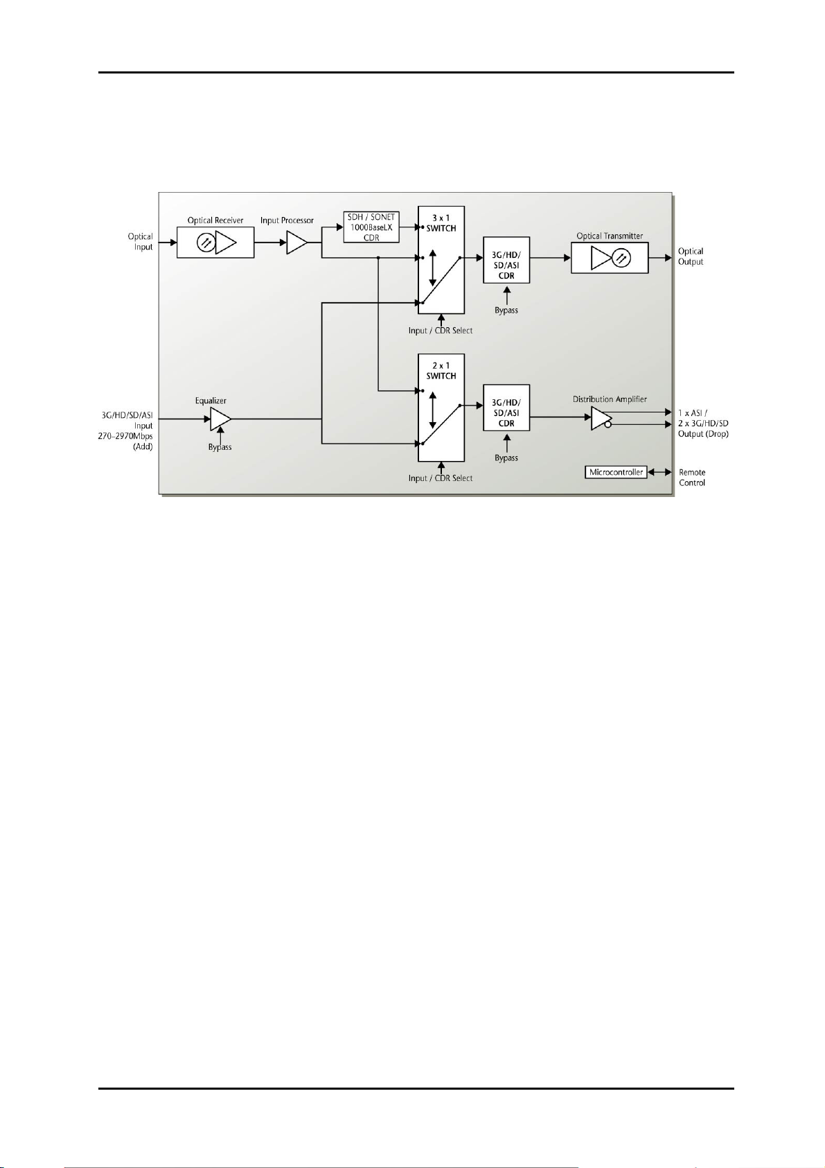
1 Product overview
Figure 1: MR-TR-3G-D Multi rate transponder for DWDM
This Flashlink MR-TR-3G-D15xx.xx is a multi bit-rate converter and transponder providing
high performance media conversion and re-clocking for SDI, SDTI and DVB-ASI signal
formats from 270Mbps to 2.97Gbps. The optical ports also provide support for SDH/SONET
and 1000Base-LX formats allowing for transponding and regeneration of optical signals.
Other signal rates from 19.4 to 2970Mbps are also supported in non-reclocked mode. The
Flashlink MR-TR-3G-D15xx.xx module can be configured as an electrical to optical and
optical to electrical converter, also called add-drop. It can also be configured as an optical to
optical transponder. It can perform optical refreshing, re-clocking and wavelength swapping.
The module offers a high sensitivity optical receiver and a narrowband temperature stabilized
0dBm or +5dBm DWDM laser. The module can be controlled, monitored and upgraded from
GYDA.
The Flashlink DWDM system uses wavelengths in accordance with the ITU-T G.694.1
recommendation. The exact wavelength needs to be specified.
The electrical input is equipped with a multi rate cable equalizer providing an equalization of
typically 70m of high quality coax cable at 2970Mbps. A distribution amplifier with 2 outputs
reduces the need for additional DAs (for DVB-ASI only one can be used).
network-electronics.com | 4

MR-TR-3G-D Rev. 0
2 Specifications
2.1 General
Power +5V DC / 3W, +15V DC/1.5W
Control Control system for access to setup and
module status with BITE (Built-In Test Equip.)
With standard ITU-T G.652 single mode fiber, we recommend to use the +5dBm DWDM
laser for distances longer than 60km for 3G-SDI.
2.2 General functions
Card labeling
Firmware upgrades
Card location in frame through blinking LED
The following parameters can be set and monitored via the web and SNMP interface:
Function Options
Laser On or off
Electrical input Normal or bypass
Telecom/data reclocker Bitrate
Reclocker 1 Enable or bypass
Reclocker 2 Enable or bypass
The following parameters can be alarmed via the web and SNMP interface:
Voltage +5V, +3.3V, +5V, +15V and +58V.
Reclocker Loss of lock
2.3 Optical Input
Receiver type Avalanche Photo Diode
Data rate optical 19.4 to 2970Mbps
Sensitivity
- 3G-SDI (2970Mbps) Better than -25dBm,
- HD-SDI (1485Mbps) Better than –30dBm,
- SDI (270Mbps) Better than –30dBm,
- SDH /SONET (2488Mbps) Better than –25dBm,
network-electronics.com | 5

MR-TR-3G-D Rev. 0
- SDH /SONET (155Mbps) Better than –30dBm,
- SDH /SONET (622Mbps) Better than –30dBm,
- 1000BaseLX (1250Mbps) Better than –25dBm
Detector overload threshold min. -5dBm
Optical wavelength 1260–1620nm
Transmission circuit fiber Single mode 9/125um
Connector return loss >40dB w/SM fiber
Detector damage threshold >0dBm
Connector SC/UPC
2.4 Optical Output
Transmission circuit fiber Single mode 9/125um
Light source DWDM DFB Laser
Optical power 0dBm (optionally +5dBm)
Optical centre wavelength According to ITU-T G.694.1 for DWDM,
Max number of channels per fiber 40 within the C-band
Channel spacing 100GHz
Max. wavelength drift ± 0.16nm
Temperature range 0 to +40 °C
Jitter (UI=Unit Interval) 0.135 UI max. @ 270Mbps,
0.2 UI max. @ 1485Mbps
0.2UI typ. @ 2970Mbps
Connector return loss >40dB w/SM fiber
Maximum reflected power 4%
Connector SC/UPC
2.5 Electrical Input
Data rate NRC 19.4 to 2970 Mbps
Data rate re-clocked 270, 1483.5, 1485, 2967 and 2970 Mbps
Equalization Automatic,
Cable equalizer and reclocker can be bypassed to
support bitrates down to 2Mbps
Impedance 75 ohm
Return loss >15dB @ 0-1500MHz
>10dB @ 1500-3000MHz
Signal level Nom. 800mV
Connector BNC
2.6 Electrical Output
Number of outputs 2
network-electronics.com | 6

MR-TR-3G-D Rev. 0
Connector BNC
Impedance 75 ohm
Return loss >15dB @ 0-1500MHz
>10dB @ 1500-3000MHz
Jitter max Max. 0.2UI
Peak to peak signal level 0.8V ± 0.1V
Signal polarity - 1 non-inverting,
- 1 inverting
2.7 Standards
Supported standards for electrical and optical ports
SMPTE SMPTE 292M, SMPTE 259M-C, SMPTE 297M,
SMPTE 305.2M, SMPTE 310M, SMPTE424M
DVB-ASI EN50083-9
Additional supported standards for the optical ports, only optical transponder configuration
SDH / SONET STM1 / OC3,
STM4 / OC12,
STM16 / OC 48,
STM16/OC48 w/FEC (2670 Mbps),
Gigabit Ethernet IEEE 802.3,
1000BaseLX for SM fiber
network-electronics.com | 7

MR-TR-3G-D Rev. 0
3 Configuration
3.1 Format configuration
The MR-TR-3G can support a number of different formats. The correct configuration
can either be set with a DIP switch or with the GYDA System Controller. The layout
of MR-TR-3G is shown in the drawing below with the DIP switch to the upper left
position.
Figure 2: MR-TR-3G-D15xx.xx board layout
DIP switch configuration must be set according to the table below:
Switch # Label Function, DIP = ON Function, DIP = OFF Comment
1 RCL1 Reclocker ON Reclocker Bypass Reclocker for optical
broadcast output
2 EQ Cable equalizer ON Cable equalizer Bypass Equalizer mode
3 RCL2 Reclocker ON Reclocker Bypass Reclocker for
electrical output
4 R1
5 R2
R2,R1
11: 1000Base-X
10: STM-16, 2488Mbps
01: STM-4, 622Mbps
00: STM-1, 155Mbps
Select format speed
for Telco reclocker
6 E/O Optical input Electrical input Select input source for
the optical output.
7 D/B Broadcast format Telco format Select Telco or
Broadcast reclocker
for optical output
when DIP#6 is on
8 E/O Optical input Electrical input Select input source for
the electrical output.
9 DOP All LED showing
optical input power
LED’s normal operation Display optical power
10 OVR Override GYDA
control
Config. with DIP
switch
GYDA control
Config. with GYDA
Select configuration
from GYDA
network-electronics.com | 8

MR-TR-3G-D Rev. 0
Bit Rate R1 R2
155Mbps Off Off
622Mbps Off On
2488Mbps On Off
Gigabit Ethernet On On
All DIP switches are off when pointing towards the release handle.
When a “Broadcast format support” is selected, all clock rates for HD-SDI, SDI and
DVB-ASI are automatically configured by the module itself.
Figur 3 3G/HD/SD-SDI Opt. to El. and El. To Opt.
Figur 4 3G/HD/SD-SDI Opt. to Opt. and El. To EL.
Figur 5 Gbe/SDH/SONET Opt. to Opt. (155Mbps) and SDI El. To El.
network-electronics.com | 9

MR-TR-3G-D Rev. 0
3.2 Optical power meter
By turning DIP#9 on, the LEDs can be used as an optical power meter. This is
practical under installation of the module. The power measurement is not accurate
but can be used as an indication of optical signal strength. Remember to turn this
function of after installation. When all LEDs are green the optical input power is
more than -6.5dBm. When all LED are off input power is below -25dBm.
Optical input power Status LED LOS/lock1 LED LOS/lock2 LED Laser fail LED
More than -6.5dBm Green Green Green Green
-7.0dBm to –8.5dBm Yellow Green Green Green
-9.0dBm to –10.5dBm Red Green Green Green
-11.0dBm to –12.5dBm Green Green Green
-13.0dBm to –14.5dBm Yellow Green Green
-15.0dBm to –16.5dBm Red Green Green
-17.0dBm to –18.0dBm Green Green
-18.5dBm to –19.0dBm Yellow Green
-19.5dBm to –20.0dBm Red Green
-21.0dBm to –22.0dBm Green
-23.0dBm to –24.0dBm Yellow
Below -25dBm Red
network-electronics.com | 10
MR-TR-3G-D Rev. 0
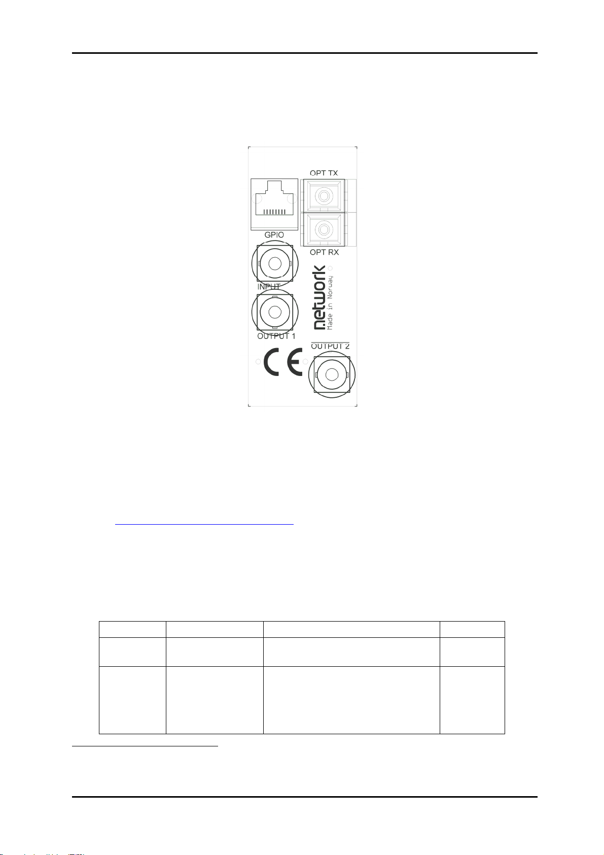
4 Connector module
The MR-TR-3G-D15xx has a dedicated connector module: MR-TR-C2. This module
is mounted at the rear of the sub-rack. The module is shown in the figure below.
Unused electrical ports should be terminated with 75ohm.
Figure 8: Connector module for MR-TR-3G
4.1 Mounting the connector module
The details of how the connector module is mounted, is found in the user manual for
the sub-rack frame FR-2RU-10-2.
This manual is also available from our web site:
http://www.network-electronics.com/.
4.2 Terminal format support
The different input and output ports on MR-TR-3G can support a number of formats.
The table below shows which signal formats are supported on the selected
terminals.
Terminal format support:
Terminal Function Supported Format Mode
INPUT Electrical input 3GHD-SDI, HD-SDI, SDI, DVB-
ASI, SMPTE310, Transparent1
Input
OPT RX Optical Input
(Receiver)
3GHD-SDI, HD-SDI, SDI, DVB-
ASI, SMPTE310,
STM-1 opt., STM-4, OC-3 opt.,
OC-12, STM-16, OC-48,
Transparent
Input
1MR-TR-3G has a “Transparent mode”. In this mode all reclockers and CDRs are switched off and no jitter
attenuation will be performed. This mode may be used for non-standard or unsupported bit rates over shorter
distances and up to 1 Gbps.
network-electronics.com | 11

MR-TR-3G-D Rev. 0
OUTPUT 1 Electrical Output –
Non inverted
3GHD-SDI, HD-SDI, SDI, DVB-
ASI, SMPTE310, Transparent
Output
OUTPUT 2 Electrical Output –
Inverted
3GHD-SDI, HD-SDI, SDI,
Transparent
Output
OPT TX Optical Output
(Transmitter)
3GHD-SDI, HD-SDI, SDI, DVB-
ASI, SMPTE310,
STM-1 opt., STM-4, OC-3 opt.,
OC-12, STM-16, OC-48,
Transparent
Output
Open Collector
Alarms
Wired alarms OC OutputGPI ALARM
Disable laser Input
network-electronics.com | 12
MR-TR-3G-D Rev. 0
5 Module status
The status of the module can be monitored in three ways.
1. GYDA System Controller (optional).
2. GPI at the rear of the sub-rack.
3. LEDs at the front of the sub-rack.
Of these three, the GPI and the LEDs are mounted on the module itself, whereas
the GYDA System Controller is a separate module giving detailed information on the
card status. The functions of the GPI and the LEDs are described in sections 5.1
and 5.2. The GYDA controller is described in a separate user manual.
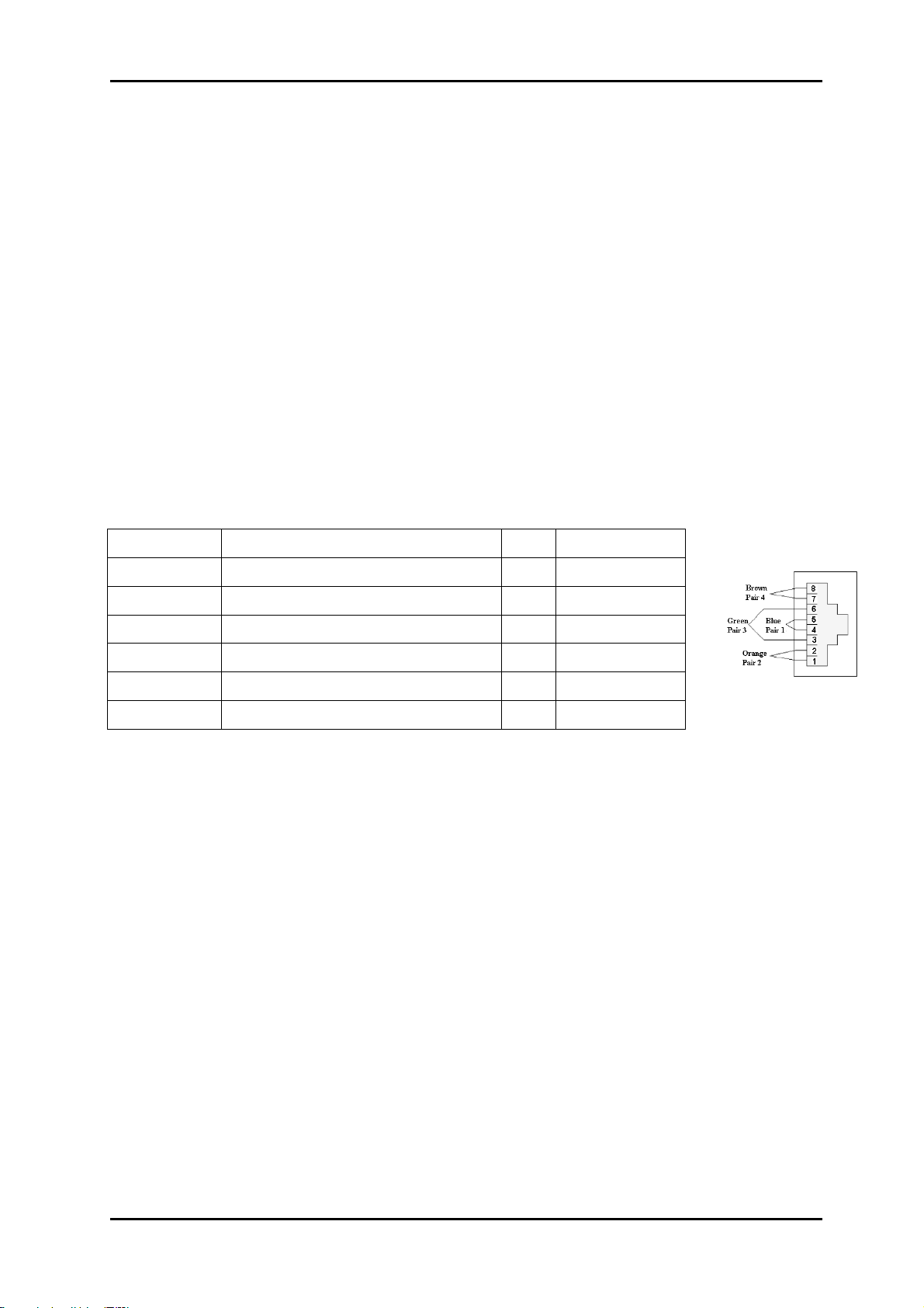
5.1 GPI Alarm – Module status outputs
These outputs can be used for wiring up alarms for third party control systems. The
GPI outputs are open collector outputs, sinking to ground when an alarm is triggered.
The GPI input laser disable will turn off the laser if this input is shortening to
ground/chassis. The GPI connector is shown in figure below.
MR-TR-3G module GPI pinning:
Signal Name Pin # Mode
Status General error status for the module Pin 1 Open Collector
Laser Fail Laser Fail Alarm Pin 2 Open Collector
LOS opt Los of optical input signal Pin 3 Open Collector
LOS el Los of electrical input signal Pin 4 Open Collector
Laser disable Turn off laser Pin 5 Input
Ground 0 volt pin Pin 8 0V.
Figure 9: GPI output.
Electrical Maximums for GPI outputs
Max current: 100mA
Max voltage: 30V
network-electronics.com | 13

MR-TR-3G-D Rev. 0
5.2 Front panel – Status monitoring
The status of the module can be easily monitored visually by the LED’s at the front
of the module. The LEDs are visible through the front panel as shown in the figure
below.
Figure 10: Front panel indicators for the MR-TR-3G.
The MR-TR-3G has 4 LED’s each showing a status corresponding to the GPI
pinning.
Diode \
State
Red LED Yellow LED Green LED No light
Status Module is faulty
Yellow blinking,
DWDM laser
temperature
stabilizing.
Module is OK
Module power is OK
Module has no
power
LOS/LOCK1 Loss of signal on
optical output
reclocker
Loss of lock on
optical output
reclocker
Signal OK on optical
output reclocker
LOS/LOCK2 Loss of signal on
electrical output
reclocker
Loss of lock on
electrical output
reclocker
Signal OK on
electrical output
reclocker
Laser fail Laser is
malfunctioning.
Laser is off Laser is OK
network-electronics.com | 14

MR-TR-3G-D Rev. 0
6 Flashlink control
This card uses the FLP 4.0 protocol. See separated documents for definition of this protocol.
network-electronics.com | 15

MR-TR-3G-D Rev. 0
7 DWDM wavelength
ITU694.1 DWDM wavelength.
No. [THz] [nm]
59 195,9 1530,33
58 195,8 1531,12
57 195,7 1531,90
56 195,6 1532,68
55 195,5 1533,47
54 195,4 1534,25
53 195,3 1535,04
52 195,2 1535,82
51 195,1 1536,61
50 195,0 1537,40
49 194,9 1538,19
48 194,8 1538,98
47 194,7 1539,77
46 194,6 1540,56
45 194,5 1541,35
44 194,4 1542,14
43 194,3 1542,94
42 194,2 1543,73
41 194,1 1544,53
40 194,0 1545,32
39 193,9 1546,12
38 193,8 1546,92
37 193,7 1547,72
36 193,6 1548,51
35 193,5 1549,32
34 193,4 1550,12
33 193,3 1550,92
32 193,2 1551,72
31 193,1 1552,52
30 193,0 1553,33
29 192,9 1554,13
28 192,8 1554,94
27 192,7 1555,75
26 192,6 1556,55
25 192,5 1557,36
24 192,4 1558,17
23 192,3 1558,98
22 192,2 1559,79
21 192,1 1560,61
20 192,0 1561,41
network-electronics.com | 16

MR-TR-3G-D Rev. 0
General environmental requirements for Network Electronics
equipment
1. The equipment will meet the guaranteed performance specification under the following
environmental conditions:
- Operating room temperature range: 0°C to 40°C
- Operating relative humidity range: <90% (non-condensing)
2. The equipment will operate without damage under the following environmental
conditions:
- Temperature range: -10°C to 55°C
- Relative humidity range: <95% (non-condensing)
network-electronics.com | 17

MR-TR-3G-D Rev. 0
Product Warranty
The warranty terms and conditions for the product(s) covered by this manual follow the
General Sales Conditions by Network Electronics AS. These conditions are available on the
company web site of Network Electronics AS:
www.network-electronics.com
network-electronics.com | 18

MR-TR-3G-D Rev. 0
Appendix A Materials declaration and recycling information
A.1 Materials declaration
For product sold into China after 1st March 2007, we comply with the “Administrative
Measure on the Control of Pollution by Electronic Information Products”. In the first stage of
this legislation, content of six hazardous materials has to be declared. The table below
shows the required information.
Toxic or hazardous substances and elements
組成名稱
Part Name
鉛
Lead
(Pb)
汞
Mercury
(Hg)
镉
Cadmium
(Cd)
六价铬
Hexavalent
Chromium
(Cr(VI))
多溴联苯
Polybrominated
biphenyls
(PBB)
多溴二苯醚
Polybrominated
diphenyl ethers
(PBDE)
<Product> O O O O O O
<Power supply, if
delivered with
unit>
O O O O O O
O: Indicates that this toxic or hazardous substance contained in all of the homogeneous materials for
this part is below the limit requirement in SJ/T11363-2006.
X: Indicates that this toxic or hazardous substance contained in at least one of the homogeneous
materials used for this part is above the limit requirement in SJ/T11363-2006.
This is indicated by the product marking:
A.2 Recycling information
Network Electronics provides assistance to customers and recyclers through our web site
http://www.network-electronics.com. Please contact Network Electronics’ Customer Support
for assistance with recycling if this site does not show the information you require.
Where it is not possible to return the product to Network Electronics or its agents for
recycling, the following general information may be of assistance:
−Before attempting disassembly, ensure the product is completely disconnected from
power and signal connections.
−All major parts are marked or labeled to show their material content.
−Depending on the date of manufacture, this product may contain lead in solder.
−Some circuit boards may contain battery-backed memory devices.
network-electronics.com | 19

EC Declaration of Conformity
MANUFACTURER Network Electronics AS
P.B. 1020, N-3204 SANDEFJORD, Norway
AUTHORISED REPRESENTATIVE
(Established within the EEA) Not applicable
MODEL NUMBER(S) MR-TR-3G-D15xx
DESCRIPTION Multi rate transponder and converter for dense wavelength
division multiplexing
DIRECTIVES this equipment complies with LVD 73/23/EEC
EMC 2004/108/EEC
HARMONISED STANDARDS applied in order to
verify compliance with Directive(s)
EN 55103-1:1996
EN 55103-2:1996
TEST REPORTS ISSUED BY Notified/Competent Body Report no:
Nemko E08503.00
TECHNICAL CONSTRUCTION FILE NO Not applicable
YEAR WHICH THE CE-MARK WAS AFFIXED 2008
TEST AUTHORIZED SIGNATORY
MANUFACTURER AUTHORISED REPRESENTATIVE
(Established within EEA) Date of Issue
2008-07-11
Place of Issue
Not applicable Sandefjord, Norway
Name Thomas Øhrbom
Position Quality Manager
(authorised signature)
Table of contents
Other network Media Converter manuals


