network SDI-OE-2 User manual

SDI-OE-2
Dual SDI Optical to Electrical Converter
Product Manual
Rev. 0

SDI-OE-2 Rev. 0
2
Network Electronics ASA
Thorøya
P.O. Box 1020
Sandefjord, Norway
Phone: +47 33 48 99 99
Fax: +47 33 48 99 98
E-mail: [email protected]
www.network-electronics.com
Service Phone: +47 90 60 99 99
Revision history
Current revision of this document is the uppermost in the table below.
Revision Replaces Date Change description
0 A 30/08/05
First official release, including updated drawings and
text.
A - 01/06/04 Preliminary version.

SDI-OE-2 Rev. 0
3
Contents
Revision history ................................................................................ 2
1 Product overview ........................................................................... 4
2 Specifications................................................................................. 5
2.1 Optical input ................................................................................................... 5
2.2 Electrical.........................................................................................................5
2.3 Electrical output..............................................................................................5
2.4 Standards .......................................................................................................5
3 Configuration ................................................................................. 6
3.1 Format configuration ......................................................................................6
3.2 Configuration examples .................................................................................7
4 Connector module ......................................................................... 8
4.1 Mounting the connector module.....................................................................8
4.2 Terminal format support .................................................................................9
5 Module status .............................................................................. 10
5.1 GPI Alarm – Module status outputs .............................................................10
5.2 Front panel – Status monitoring ...................................................................11
6 Laser safety precautions.............................................................. 12
General environmental requirements for flashlink®equipment....... 13
Certificate of Conformity ................................................................. 14
Product Warranty............................................................................ 15

SDI-OE-2 Rev. 0
4
1 Product overview
The flashlink®SDI-OE-2 is a dual multi bit-rate optical to electrical converter
module providing high performance media conversion for various signal
formats from 19.4Mbps up to 540Mbps. This state of the art unit offers a high
sensitivity PIN diode technology with long wavelength on single mode fiber.
Unmatched signal accuracy, even in critical applications with pathological
signal patterns makes the HD-OE-2 the first choice for all optical transport
demands.
The SDI-OE-2 can transport all SD signal formats in addition to DVB-ASI and
SMPTE 310. It performs optical refreshing and signal reclocking, which is
selectable on application. The optical input comes with a sophisticated PIN
diode with a sensitivity typically better than –30dBm operating in the 2nd and
3rd optical windows. The open system platform of Network Electronics
flashlink®system allows easy interoperability with third party fiber optical
systems.
The two independent electrical outputs are equipped with a distribution
amplifier where 2 outputs reduces the need for additional DA’s.
Figure 1: SDI-OE-2 Dual SDI O/E converter.

SDI-OE-2 Rev. 0
5
2 Specifications
2.1 Optical input
Data rate optical: 19.4 – 540 Mbps.
Sensitivity: Better than -25dBm
Detector overload threshold: Min. 0dBm
Optical wavelength: 2nd and 3rd optical window,
1200 - 1600nm.
Transmission circuit fiber: Single Mode 9/125um,
Multi Mode 9/125um compatible.
Connector return loss: >40dB w/ SM fiber.
Connector: SC/UPC.
2.2 Electrical
Power: +5V DC / 2.9W Max.
Control: Control system for access to setup and module status
with BITE (Built-In Test Equipment).
2.3 Electrical output
Number of outputs: 1.
Connector: BNC.
Impedance: 75 ohm.
Return loss: >15dB @ 540MHz.
Jitter (UI = Unit Interval): Max. 0.2UI.
Peak to peak signal level: 0.8V ±0.1V.
Signal polarity: 2 non-inverting.
2.4 Standards
Supported standards for electrical and optical ports:
SMPTE: SMPTE 259M, SMPTE 297, SMPTE 305M, SMPTE 310.
DVB-ASI: EN50083-9.

SDI-OE-2 Rev. 0
6
3 Configuration
3.1 Format configuration
The SDI-OE-2 can support a number of different broadcast formats. The
correct configuration can either be set with a DIP switch or with the GYDA
Control System. The layout of SDI-OE-2 is shown in the drawing below with
the DIP switch to the upper left position.
Figure 2: SDI-OE-2 board layout.
DIP switch configuration must be set according to the table below:
Switch # Label Function, DIP = ON Function, DIP = OFF Comment
1 RCL1 Reclocker 1 ON Reclocker 1 bypass Reclocker mode
2 PRI1 Input 1 selected Input 2 selected Output 1
3 ASI1 DVB-ASI Reclocker
support
SDI 177Mbps Reclocker
support
Select ASI or
177Mbps support
4 RCL2 Reclocker 2 ON Reclocker 2 bypass Reclocker mode
5 PRI2 Input 2 selected Input 1 selected Output 2
6 ASI2 DVB-ASI Reclocker
support
SDI 177Mbps Reclocker
support
Select ASI or
177Mbps support
7 SWP Normal operation Change over
functionality
8 OVR Override GYDA
control. Config. with
DIP switch
GYDA control. Config.
with GYDA
Select configuration
from GYDA
All DIP switches are off when pointing towards the release handle.
All clock rates for SDI and DVB-ASI are automatically configured by the
module itself.

SDI-OE-2 Rev. 0
7
3.2 Configuration examples
Figure 3: Normal operation. Signal on input 2 not present.
Figure 4: Change over operation. Priority on input 2. Los of signal on input 2.
SDI-OE-2 will switch back to input 2 when signal is present.
Normal operation.
No change over
functionality.
Input 1 is selected
Normal operation.
No change over
functionality.
Input 2 is selected
Change over.
Priority on input 2
Change over.
Priority on input 2
SDI-OE-2 Rev. 0
8
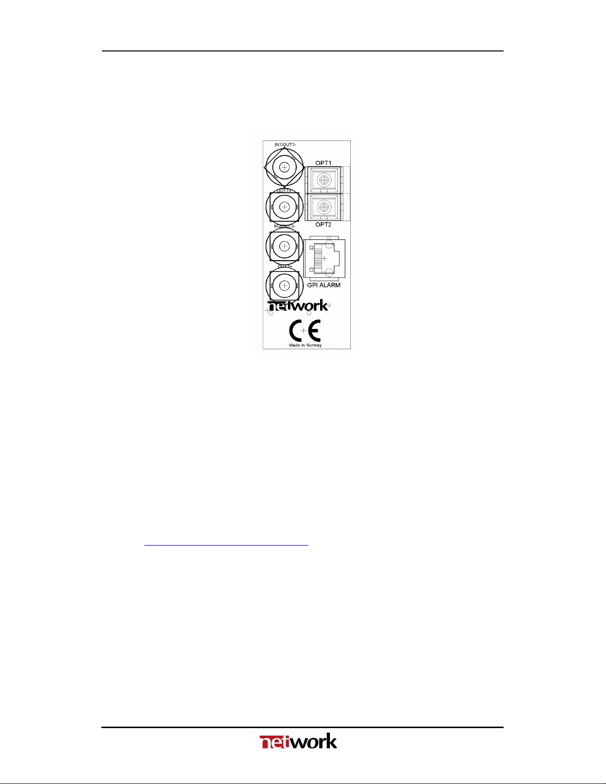
4 Connector module
The SDI-OE-2 has a dedicated connector module: HD-EO-2-C1. This module
is mounted at the rear of the sub-rack. The module is shown in the figure
below.
Figure 5: Connector module for SDI-OE-2.
In typical use a SDI-EO-2 / SDI-OE-2 module at each end will be used. Two
channels simultaneously can be converted from optical to electrical channels
The electrical input signal is connected to the INx input on the transmitting
SDI-EO-2, and the electrical output is connected to corresponding the OUTx+
or OUTx- output BNC on the receiving SDI-OE-2. The fibre cable is connected
to the corresponding optical port (OPT1 uses IN1/OUT1- and OUT1+ and
OPT2 uses IN2/OUT2- and OUT2+).
4.1 Mounting the connector module
The details of how the connector module is mounted, is found in the user
manual for the sub-rack frame FR-2RU-10-2.
This manual is also available from our web site:
http://www.network-electronics.com/.

SDI-OE-2 Rev. 0
9
4.2 Terminal format support
The different input and output ports on SDI-OE-2 can support a number of
formats. The table below shows which signal formats are supported on the
selected terminals.
Terminal format support:
Terminal Function Supported Format Mode
OPT1
OPT2
Optical output SDI, DVB-ASI, SMPTE310,
Transparent∗
Output
OUT1+
OUT2+
Electrical Output –
Non-inverted
Reclocked DA
output
SDI, DVB-ASI, SMPTE310,
Transparent*
Output
OUT1-
OUT2-
Electrical Output –
Inverted Reclocked
DA inverted output
(SDI-OE-2 has
non-inverted
outputs)
SDI, Transparent* Output
GPI ALARM Open Collector
Alarms
Wired alarms OC Output
∗SDI-OE-2 has a “Transparent mode”. In this mode all reclockers are switched off and no jitter attenuation
will be performed. This mode may be used for non-standard or unsupported bit rates over shorter
distances and up to 1 Gbps.

SDI-OE-2 Rev. 0
10
5 Module status
The status of the module can be monitored in three ways.
1. GYDA System Controller (optional).
2. GPI at the rear of the sub-rack.
3. LED’s at the front of the sub-rack.
Of these three, the GPI and the LED’s are mounted on the module itself,
whereas the GYDA System Controller is a separate module giving detailed
information on the card status. The functions of the GPI and the LED’s are
described in sections 5.1 and 5.2. The GYDA controller is described in a
separate user manual.
5.1 GPI Alarm – Module status outputs
These outputs can be used for wiring up alarms for third party control systems.
The GPI outputs are open collector outputs, sinking to ground when an alarm
is triggered. The GPI connector is shown in figure below.
SDI-OE-2 module GPI pinning:
Signal Name Pin # Mode
Status General error status for the module Pin 1 Open Collector
LOS1 Loss of Signal on selected input Pin 2 Open Collector
LOS2 Loss of Signal on selected input Pin 3 Open Collector
Not in use Pin 4 Open Collector
Ground 0 volt pin Pin 8 0V.
Figure 6: GPI output.
Electrical Maximums for GPI outputs
Max current: 100mA
Max voltage: 30V
SDI-OE-2 Rev. 0
11
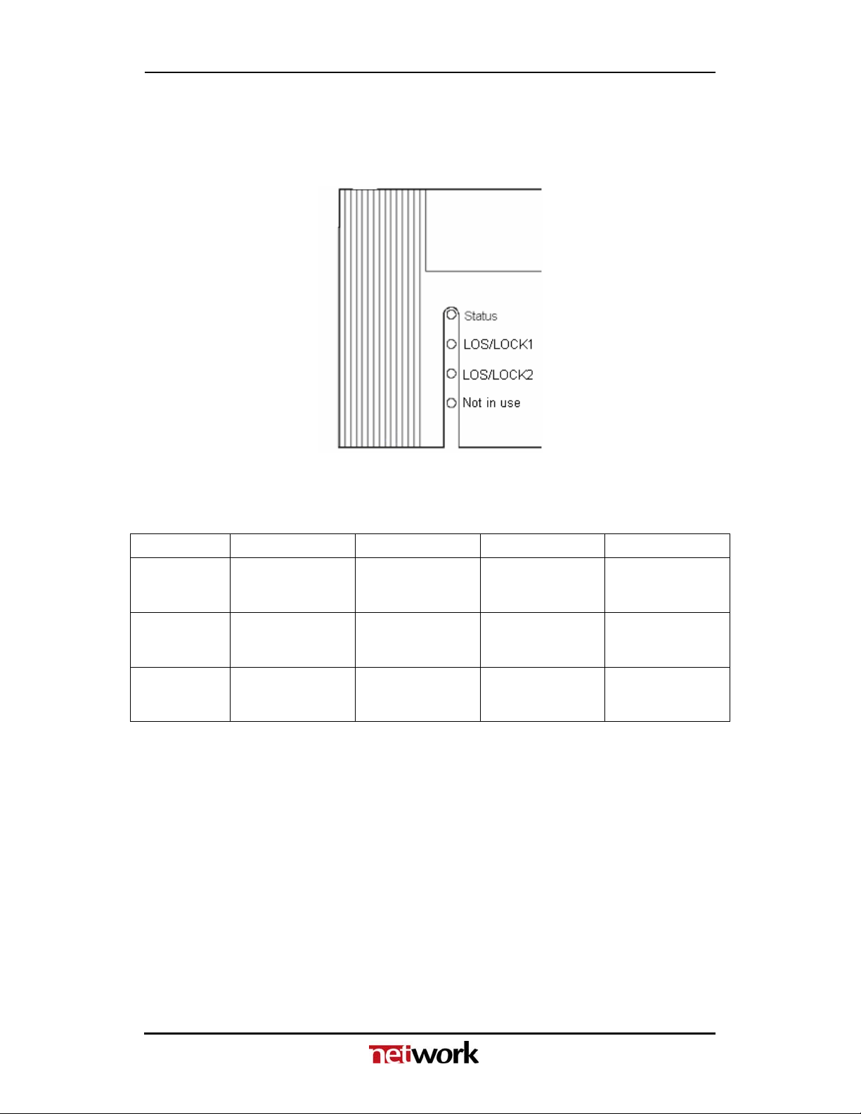
5.2 Front panel – Status monitoring
The status of the module can be easily monitored visually by the LED’s at the
front of the module. The LED’s are visible through the front panel as shown in
the figure below.
Figure 7: Front panel indicators for the SDI-OE-2.
The SDI-OE-2 has 4 LED’s each showing a status corresponding to the GPI
pinning.
Diode \ State Red LED Green LED Orange LED No light
Status Module is faulty,
or module is
initialising.
Module is OK
Module power is
OK
Module has no
power
LOS/LOCK1 Loss of optical
modulated signal.
Signal is present
and reclocker is
locked
Signal is present,
but reclocker is
out of lock
LOS/LOCK2 Loss of optical
modulated signal.
Signal is present
and reclocker is
locked
Signal is present,
but reclocker is
out of lock

SDI-OE-2 Rev. 0
12
6 Laser safety precautions
Guidelines to limit hazards from laser exposure.
All the available EO units in the flashlinkrange include a laser.
Therefore this note on laser safety should be read thoroughly.
The lasers emit light at 1310 nm or 1550 nm. This means that the human eye
cannot see the beam, and the blink reflex cannot protect the eye. (The human
eye can see light between 400 nm to 700 nm).
A laser beam can be harmful to the human eye (depending on laser power
and exposure time), therefore:
Instruments exist to verify light output power: Power meters, IR-cards etc.
Flashlinkfeatures:
All the laser module cards in the flashlinkproduct range, are Class 1
laser products according to IEC 825-1 1993, and class I according to
21 CFR 1040.10 when used in normal operation.
More details can be found in the user manual for the FR-2RU-10-2 frame.
Maximum output power1: 5 mW.
Operating wavelengths: > 1270 nm.
< 5mW
>1270nm
1Max power is for safety analysis only and does not represent device performance.
Note!
BE CAREFUL WHEN CONNECTING / DISCONNECTING
FIBER PIGTAILS (ENDS).
NEVER LOOK DIRECTLY INTO THE PIGTAIL OF THE
LASER/FIBER.
NEVER USE MICROSCOPES, MAGNIFYING GLASSES OR
EYE LOUPES TO LOOK INTO A FIBER END.
USE LASER SAFETY GOGGLES BLOCKING LIGHT AT
1310 nm AND AT 1550 nm.

SDI-OE-2 Rev. 0
13
General environmental requirements for flashlink®equipment
1. The equipment will meet the guaranteed performance specification under the
following environmental conditions:
- Operating room temperature range: 0°C to 40°C
- Operating relative humidity range: < 90% (non-condensing)
2. The equipment will operate without damage under the following environmental
conditions:
- Temperature range: -10°C to 55°C
- Relative humidity range: < 95% (non-condensing)
3. Electromagnetic compatibility conditions:
- Emissions: EN 55103-1 (Directive 89/336/EEC)
- Immunity: EN 55103-2 (Directive 89/336/EEC)
SDI-OE-2 Rev. 0
14
Certificate of Conformity
Network Electronics ASA
N-3204 Sandefjord
Norway
Company Registration Number:
NO 976 584 201 MVA
Declares under sole responsibility that the product:
Product Name: SDI-OE-2
Product Description: Dual SDI Optical to Electrical
Converter
To which this declaration relates are of Norwegian origin and are in conformity with the
following standards:
EN 55103-1: 1996 Generic Emissions Standard
EN 55103-2: 1996 Generic Immunity Standard

SDI-OE-2 Rev. 0
15
Product Warranty
The warranty terms and conditions for the SDI-OE-2 follow the General Sales
Conditions by Network Electronics ASA. These conditions are available on the
company web site of Network Electronics ASA:
www.network-electronics.com
Table of contents
Other network Media Converter manuals


Popular Media Converter manuals by other brands

Arcam
Arcam Black Box 500 Service manual
 user guide")
Transition Networks
Transition Networks C/A-CF-02(SM) user guide

Extron electronics
Extron electronics IN1606 user guide

Technica
Technica 100BASE-T1 MediaConverter BCM user manual

Theme scene
Theme scene ThemeScene HD3000 user guide

Allied Telesis
Allied Telesis AT-MC13 user guide


