Micronor MR330 Series User manual

© COPYRIGHT 2011-2016 MICRONOR INC.
CAMARILLO, CALIFORNIA
UNITED STATES OF AMERICA
MICRONOR INC.
900 Calle Plano, Suite K
Camarillo, CA 93012 USA
PH +1-805-389-6600
FX +1-805-389-6605
sales@micronor.com
www.micronor.com
For Support in Europe:
MICRONOR AG
Pumpwerkstrasse 32
CH-8105 Regensdorf
Switzerland
PH +41-44-843-4020
FX +41-44-843-4039
sales@micronor.ch
www.micronor.com
Notice of Proprietary Rights
The design concepts and engineering details embodied in this manual, which are the property of MICRONOR INC., are to be
maintained in strict confidence; no element or detail of this manual is to be spuriously used, nor disclosed, without the express
written permission of MICRONOR INC. All rightsare reserved. No part of this publication may be reproduced, stored in a retrieval
system, or transmitted in any form or by any means, electronic, mechanical, photocopying, recording, or otherwise, without prior
written permission from MICRONOR INC.
MR330 Series
ZapFREE® Fiber Optic
Absolute Encoder System
Instruction Manual
Doc No: 98-0330-11
Revision G dated 08-08-2016

MICRONOR INC.
MR330 Fiber Optic Position Sensor System
Page 2 of 62
Revision History
Revision
Date
Notes
A
1 – July – 2011
Initial Release
B
1 – July – 2011
Added Modbus and SSI Description
C
9 – July – 2011
Production Release
D
January – 2014
Feature Updates, 14-bit Resolution Capability, SSI Display in
ZapView, & Added MR338
E
May – 2014
Sensor Pairing without Software Procedure Update
F
October – 2015
Updated to New Camarillo Address and Telephone Number
G
8-August-2016
Ex, Specifications, Appearance, and Formatting Updates
Added reference to IECEx Test Report

MICRONOR INC.
MR330 Fiber Optic Position Sensor System
Page 3 of 62
Table of Contents
Revision History ..........................................................................................................................................2
1. Product Description.............................................................................................................................5
1.1 Position Sensor Background .......................................................................................... 5
1.2 Fiber Optic Position Sensor ............................................................................................ 5
1.3 Features........................................................................................................................... 6
2. Initial Preparation................................................................................................................................7
2.1 Unpacking and Inspection .............................................................................................. 7
2.2 Damage in Shipment ...................................................................................................... 7
2.3 Standard Contents.......................................................................................................... 7
3. Installation and Operation ..................................................................................................................8
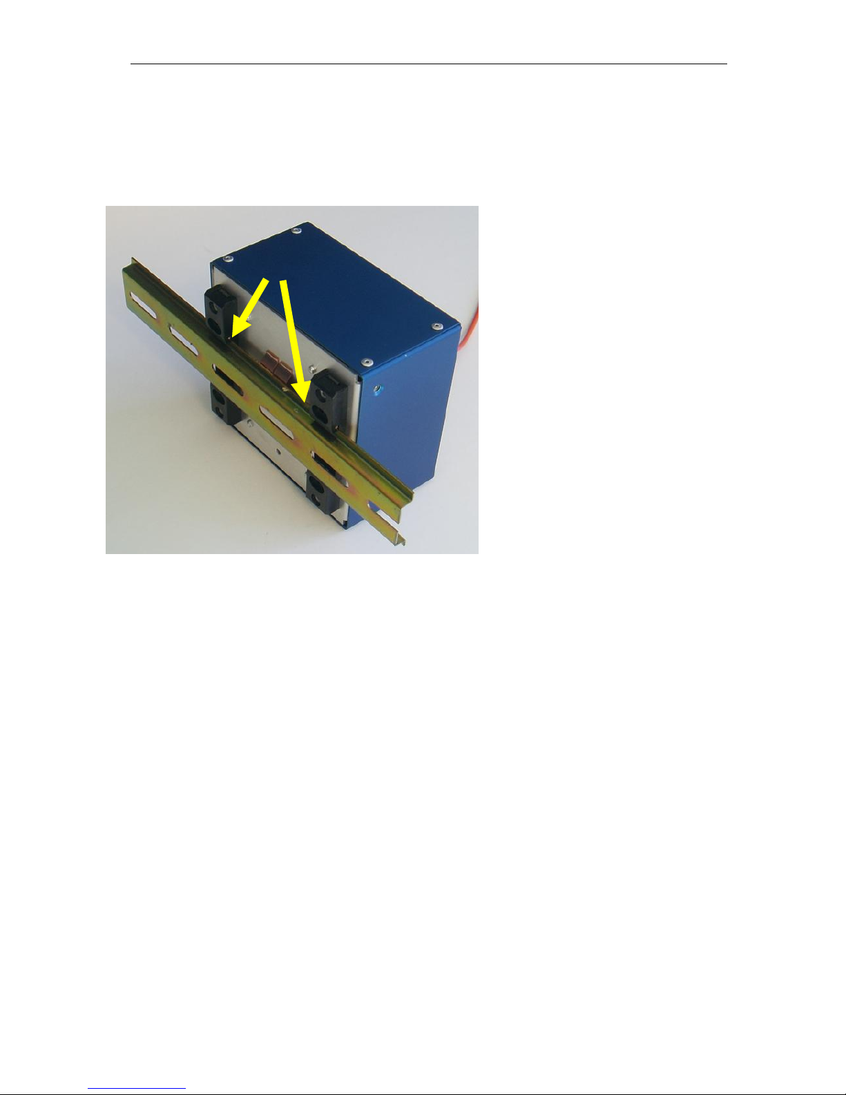
3.1 Mounting the Sensor Unit............................................................................................... 8
3.2 Mounting the Controller Unit .......................................................................................... 9
3.3 Connecting the Controller.............................................................................................10
3.4 System Start-Up without PC Computer ........................................................................13
3.5 Functional System Overview.........................................................................................14
3.6 Turn-Counter or Turn-Counter Size...............................................................................16
3.7 Multi-Turn Operation .....................................................................................................17
3.8 Battery Backup for Multi-Turn Operation.....................................................................18
3.9 SSI Interface ..................................................................................................................18
3.10 Voltage Output...............................................................................................................20
3.11 Isolated Current Output (4-20mA)................................................................................22
3.12 Digital Set Points...........................................................................................................23
4. Serial Communication – MODBUS.................................................................................................. 25
4.1 USB-Serial Emulator......................................................................................................25
4.2 Serial Interface Specification .......................................................................................26
4.3 Physical Connection for ModBus operation ................................................................26
4.4 Serial Bus Termination Resistor...................................................................................27
4.5 MODBUS Communications Protocol ............................................................................27
5. MR330 - Error Handling and Troubleshooting................................................................................ 34
5.1 Explanation of Status and Error Handling ...................................................................34
5.2 Explanation of Status and Error Indication..................................................................34
5.3 Reading the Error Counters..........................................................................................38
5.4 About Statistical Read Error Determination ................................................................38
5.5 Warranty Information ....................................................................................................40
6. Specifications................................................................................................................................... 41

MICRONOR INC.
MR330 Fiber Optic Position Sensor System
Page 4 of 62
6.1 MR332 Sensor Specifications......................................................................................41
6.2 MR338 MRI Safe Sensor Specifications .....................................................................42
6.3 MR330 Controller Specification...................................................................................43
7. ZapView™ Software.......................................................................................................................... 44
7.1 ZapView™ - MR330 Setup Software Installation Guide .............................................46
7.2 ZapView™ - Serves as Substitute SSI Display .............................................................50
8. MR330 Theory of Operation ............................................................................................................ 54
9. Mechanical Reference Drawings..................................................................................................... 57
9.1 MR330-1 Controller ......................................................................................................57
9.2 MR332 Sensor ..............................................................................................................57
9.3 MR338 Sensor ..............................................................................................................57
9.4 MR330 Series Declaration of Conformity....................................................................57
List of Figures
Figure 1. Micronor MR330 Fiber Optic Position Sensor System .............................................. 5
Figure 2. Sensor mounted using Servo Clamps.......................................................................... 8
Figure 3. Mounting MR330 Controller on DIN Rail..................................................................... 9
Figure 4. How to insert and remove wires from WAGO plug....................................................11
Figure 5. Inserting/Removing WAGO plug from MR330 unit...................................................12
Figure 6. Block Diagram of MR330 System..............................................................................15
Figure 7. SSI Interface Connector - J2 (10 pin).........................................................................18
Figure 8. SSI Termination Resistor Switch ................................................................................19
Figure 9. SSI Single Transmission Timing .................................................................................19
Figure 10. Mode 1 Voltage Output ...........................................................................................20
Figure 11. Mode 2 Voltage Output ............................................................................................21
Figure 12. Mode 3 Voltage Output ............................................................................................21
Figure 13. Analog Output with an oscillating shaft input .........................................................22
Figure 14. Mode 1 Current Output ............................................................................................23
Figure 15. Mode 2 Current Output ............................................................................................23
Figure 16. Photograph of MR232-1 RS422/RS485-to-RS232 Adapter Cable. .....................46
Figure 17. Block Diagram of the Fiber Optic Position Sensor System ....................................54
Figure 18. Sensor Head Principle of operation.........................................................................55
Figure 19. Light pattern on disk.................................................................................................55
Figure 20. Code Disk Pattern Representation ..........................................................................56
List of Tables
Table 1. Table of Error Codes.....................................................................................................36

MICRONOR INC.
MR330 Fiber Optic Position Sensor System
Page 5 of 62
1. Product Description
1.1 Position Sensor Background
Position sensors are typically used to provide an absolute position from a mechanical moving
device to a controller unit. The position information is either used to measure a position or to
close the servo loop for an automatic positioning system. The key characteristics of an
absolute position sensor are:
•Accuracy
•Resolution
•Time response of the actual position
1.2 Fiber Optic Position Sensor
The MR330 series fiber optic position sensor system is an innovative all-optical design
immune to any electro-magnetic interference such as lightning, radiation, magnetic fields and
other harsh environmental conditions. The fiber optic aspect of the sensor also makes it
perfectly suited for long distance position sensing over hundreds of meters without being
affected by ground loop problems. This innovative product measures absolute angular
position from 0° to 360° with 14-bit resolution at speeds exceeding 2500 rpm and distances
up to 300 meters.
Figure 1. Micronor MR330 Fiber Optic Position Sensor System
The sensor modulates the optical signal based on the exact position of the sensor disk. This
modulated optical signal is analyzed within the controller and translated into the position
signal. Because the sensor is electrically passive it can be deployed in EMI/RFI intense
environment without being disturbed by such interference.
The position signal is measured and updated at a rate of 1.2 kHz. The controller provides a
host of interface capabilities such scalable analog voltage and current outputs, digital SSI
(Serial Synchronous Interface) output and a MODBUS compatible serial interface.

MICRONOR INC.
MR330 Fiber Optic Position Sensor System
Page 6 of 62
1.3 Features
•Absolute Angular Position with 14-bit (13,950) Resolution
•Multi-turn tracking to 12-bits (4096 turns)
•Immune to Electrical Interference
•Zero Emitted Electrical Radiation
•Long Distance Transmission without Interference
•Utilizes standard 62.5/125µm communications fiber
•Multiple interfaces built-in into one unit!
oSSI Interface
oMODBUS RTU via RS422/RS485 serial interface.
oUSB Interface
oTwo Scalable Analog Position Outputs (±10V and 4-20mA)
oTwo Programmable Digital Set-Points
•User settable Zero Position
•External Zero Position input.
•Zero Position Indicator LED for easy installation
•Powers from +12V DC to +32VDC
•Low Energy consumption, < 1.8 Watts
•Built-In Battery Backup connection.
•ZapViewTM Setup Software
•MRI Safe Model MR338 Sensor available
•Ex classified “Inherently Safe, Simple Mechanical Device”, i.e. sensor can be installed
in all manner of hazardous location or explosive atmosphere – mines, gas or dust

MICRONOR INC.
MR330 Fiber Optic Position Sensor System
Page 7 of 62
2. Initial Preparation
2.1 Unpacking and Inspection
The unit was carefully inspected mechanically and electrically before shipment. When received,
the shipping carton should contain the following items listed below.Account for and inspect each
item before the carton is discarded. In the event of a damaged instrument, write or call your
nearest MICRONOR office in the U.S. A. Please retain the shipping container in case reshipment
is required for any reason.
2.2 Damage in Shipment
If you receive a damaged instrument you should:
1. Report the damage to your shipper immediately.
2. Inform MICRONOR
3. Save all shipping cartons.
Failure to follow this procedure may affect your claim for compensation.
2.3 Standard Contents
MR332 Sensor:
•MR332 Sensor Unit with fiber cable length as ordered and terminated with Duplex LC
connector.
•Test Protocol Sheet
•Instruction Manual (this document, one soft copy supplied with each shipment)
MR330-1 SSI Controller Module:
•MR330-1 Controller Module
•WAGO type connector inserted as part of the unit.
•WAGO connector wiring tool.
•WAGO strain relief, quantity 3
•MR330 Short Instruction Manual (Paper Copy)
•MR330 Full Instruction Manual (supplied as PDF on CDROM)
•ZapView™ Setup Software (on CDROM)
Available accessories (must be ordered separately):
•MR332A - set of 3 synchro clamps and screws
•MR320-D06CXX cable assemblies (for extended links)
•MR320C Duplex LC mating adapter (for connecting cable segments)

MICRONOR INC.
MR330 Fiber Optic Position Sensor System
Page 8 of 62
3. Installation and Operation
3.1 Mounting the Sensor Unit
The sensor unit has a 58mm flange. Use at
least 3 clamp nuts to secure the sensor to
the shaft. A set of 3 clamps with screws can
be ordered as model MR332A.
A flexible shaft coupling should be used for
coupling to external motor shaft.
The shaft should be oriented to coincide with the system midpoint. With the sensor powered
ON turn the shaft until the ZERO indicator LED is ON. When this LED is ON, then the sensor
is within a few degrees of the zero position. Then mechanically align the shaft with the system.
It is also possible to mount the sensor regardless of the zero position and then position the
entire system to the desired origin (zero) location. With the MR330 unit powered up and the
fiber connected activate the ZERO button on the MR330 unit. This will teach the sensor the
new zero point and the unit will retain that position even when electrical power is turned off.
Figure 2. Sensor mounted using Servo Clamps

MICRONOR INC.
MR330 Fiber Optic Position Sensor System
Page 9 of 62
3.2 Mounting the Controller Unit
The controller unit may be best mounted on DIN rails. There are two clamps on the bottom of
the unit. Slide the unit onto the DIN rail starting from top and hook the bottom onto the rail.
To remove the unit from the rail
press the unit firmly down and lift
the bottom away from the DIN
rail.
Figure 3. Mounting MR330 Controller on DIN Rail
Spring Captured

MICRONOR INC.
MR330 Fiber Optic Position Sensor System
Page 10 of 62
3.3 Connecting the Controller
A duplex fiber optic cable is used to interconnect the sensor and controller. The sensor
incorporates a 3m optical pigtail (or as specified by customer). If a longer connection to the
controller is required then an extension fiber cable having duplex LC connector may be used.
Remove the dust cap form both the connector on the cable and the receptacle on the
controller. Insert the LC connector as shown. There should be a positive click when the
connector is engaged properly.
Connections to the MR330 Controller Module
Electrical Connections MR330 Controller
J2 Connections
Data SSI and
Analog Output
1
±10V position output
2
GND
3
SSI Clock +
4
SSI Clock -
5
SSI Data +
6
SSI Data -
7
+24V IN
8
GND
9
4-20mA Out +
10
4-20mA Out -
J1 Connections
and Power Supply
1
ZERO OUT
2
GND
3
Set Point 1
4
GND
5
Set Point 2
6
GND
7
BAT+
8
24V
9
GND (power)
10
+Vs (power)
(15V to +32V)
11
ZERO IN
12
Shield
J3 Connections
RS422/485 Serial I/O
1
GND
2
+5V Out
3
TX+ →
4
TX-→
5
RCV+ ←
6
RCV-←
CLICK !

MICRONOR INC.
MR330 Fiber Optic Position Sensor System
Page 11 of 62
All three Terminal Connectors are WAGO type Mini Multi Connection System with 2.5mm
spacing. One each of these connectors are included.
WAGO Connector
Part Numbers for Terminal Connectors
Location
MICRONOR PN
WAGO PN
J1
63-733-112
733-112
J2
63-733-110
733-110
J3
63-733-106
733-106
Tool
63-233-335
233-335
These terminal connectors are non-screw connections and accept wires from AWG20 through
AWG 28 or 0.5mm2to 0.08mm2. The WAGO terminal blocks are a convenient way to pre-wire
harnesses.
Figure 4. How to insert and remove wires from WAGO plug.
Making connections to the MR330 Controller is easy via the WAGO QuickConnect plugs:
1. Strip the wire approx. 0.22” (5mm to 6mm) length.
2. Insert the white operating tool into the square hole of the terminal.
3. Then insert the stripped wire all the way down and remove the operating tool.
4. When wiring completed, simply insert the WAGO plug to the appropriate interface
connector on MR330 (J1, J2 or J3). To remove the WAGO plug, grab top and bottom of
plug and pull to disconnect

MICRONOR INC.
MR330 Fiber Optic Position Sensor System
Page 12 of 62
Apply 24VDC electrical power to the controller unit. The current consumption is typically 70mA
and should be less then 100mA at all times.
The controller PWR LED will light up. A steady light indicates proper operation and the sensor is
installed correctly. (Blinking of this LED indicates an error condition. See Section 5x.xx for error
codes)
The ZERO indicator LED will be On when the position sensor is at 0 position.
The RUN indicator LED will be ON whenever the sensor is in motion.
Status information is provided by a blinking PWR LED.
See Section 5 for more details regarding status and error codes.
Blinks
Code Description
Steady ON
System is ok. Shaft position within measuring range
1
Outside Range for Turn-Restore
2
Bad position signal.
-> Sensor may need to be “paired” to the controller box
3
No optical signal, i.e.Fiber disconnected
4
System Problem
For streamlining wiring the WAGO
connectors are removable as
plugs. This is a practical
arrangement when wiring
harnesses be prepared without
the unit present or when the
controller unit needs to be
exchanged for maintenance
purposes.
Figure 5. Inserting/Removing WAGO plug from MR330 unit

MICRONOR INC.
MR330 Fiber Optic Position Sensor System
Page 13 of 62
3.4 System Start-Up without PC Computer
It is recommended to use a PC (laptop) computer when bringing an MR330 Position Sensing
System on-line. Micronor provides the ZapView™ software for setting parameters and for
diagnostics of the system. Checking the system after installation with ZapView™ provides
assurance that the installation is complete and the system functions perfectly.
There may be instances where no PC is available. Installations that use only the analog or SSI
outputs do not require specific programming on-site, especially if the MR330 controller was
specially pre-configured for the customer's application at the factory - or the customer is using
the default settings.
Install the sensor as described above, connect the fiber optic line and apply 24V to the MR330
controller. If the power LED comes ON steady state, that means all tests are good and the
system is ready to go. If the LED indicates system OK, then all is left to set the home (zero)
position. Bring the system to the desired home location and activated the recessed button as
shown in figure below.
If the power LED does not turn steady state after
approximately 5 seconds that indicates the unit is not
fully functional. Count the number of blinks and
proceed as shown in table below.
Blinks
Meaning
Remedy
1
No Connection
Check the optical fiber link for high losses
2
Requires Pairing
System needs to correct for optical fiber losses and
discrepancies in Sensor Unit.
Perform pairing operation, which can be done without a
PC.
3
Supply Voltage
Either internal or external supply voltages are out of
range. Check the 24V power supply and the connection
to the MR330 controller. Also check current draw of the
unit, it should be less than 80mA.
When the MR330 controller indicates a Status, then it is advisable to use a ZapView™ on a
PC and connect the PC via USB or serial interface to the MR330 to troubleshoot the problem.

MICRONOR INC.
MR330 Fiber Optic Position Sensor System
Page 14 of 62
Pairing sensor and controller without a PC and ZapView™ :
Connect the system and make sure you have access to the sensor, so that the sensor can be
rotated during the pairing process. If the machine can slowly drive (~60rpm or higher) the
sensor then that would work well. Otherwise the sensor maybe turned by hand, but it should
be a somewhat steady motion.
Steps:
a.) With the controller module powered off start the process by holding down the ZERO
(home position) switch while turning the power on (24VDC).
b.) Release the ZERO switch and the “running” and zero LED should blink
simultaneously.
c.) Now turn the sensor steadily until the LED’s stop blinking.
d.) Once the two LED’s stop blinking the unit will restart itself and the Power LED should
go On steady. If the process does not seem to end after approx. 30 seconds. Remove
power from the unit and repeat the process above.
3.5 Functional System Overview
The MR330 system consists of an electronically passive Sensor (MR332) which is connected
to the MR330 Controller via a duplex 62.5/125um optical fiber link.
The MR330 Controller constantly probes the sensor by sending a short optical pulse to the
sensor. The sensor modulates the optical spectrum of that light pulse depending on the
current sensor position.
The MR330 controller receives this modulated optical signal and calculates the position. The
system is a “Single Turn Absolute” position sensor. However, the controller provides
mechanism to use the system as a quasi multi-turn position sensor.
Figure 6 shows the functional blocks to which the user interfaces. This block-diagram does
not show the details of the sophisticated optical measurements and algorithms employed to
extract the position information.
The default single-turn resolution is 13 bits (can be set to 14 bits / 39850 counts via ZAPPY
configuration software) and there is also a 12-bit turn counter which keeps track of the full
turns of the sensor while the unit powered up and the sensor is connected with the fiber optic
link. Both absolute single-turn position (13 bits) and the turn counter (12bits) are combined
to provide a 25-bit position signal. The user has the option to mask the turn counter and thus
limit the output to match the physical setup. If the sensor is only used to measure a range
over , let’s say, 5 turns then the user may limit the turn counter to 3bits providing a range of
maximum 8 turns until the output wraps around back to zero. Using the example above, the
readout position would range from 0 to 65,535 (3 turns times 8192 resolution per turn).
As the block diagram shows, the position signal is routed to all the various output interfaces
built into the unit.

MICRONOR INC.
MR330 Fiber Optic Position Sensor System
Page 15 of 62
Figure 6. Block Diagram of MR330 System
The Serial Interface conforms to the MODBUS standard and is the main communications
interface, specifically also for setup and configuration purposes. To make interfacing PC
computers easy there is a built-in USB interface as well.
The SSI interface is often used to interface with PLC controllers and other automation
equipment. This output always toggles out fixed 25 bits, but derives its information after the
turn-mask and therefore maximum read-out values are restricted to what the turn-mask is
configured to.
The Current Output is a fully isolated 4-20mA loop powered output. It has three programmable
operating modes and scaling is over the full range of 25 bits. Digital to analog output
resolution is 13 bits
The Voltage Output provides voltage from -10V to +10V and it has four programmable
operating modes and scaling is over the full range of 25 bits. Digital to analog resolution is 12
bits plus sign.
Absolute
Single turn 13-bit
Turn
Mask
Voltage
Scaling
Mode
Current Scaling
Mode
RESET
Set-Point 1
Set-Point 2
SSI
pos_full
pos_rprt
J3J2J1
ZERO Indicator
RS422/485
USB
Serial
Interface
USB
Turn
Counter
12bit
Zero Offset
Full Position

MICRONOR INC.
MR330 Fiber Optic Position Sensor System
Page 16 of 62
Two independent digital Set-Point outputs provide a Limit Switch like behavior. These outputs
can be programmed to turn ON or OFF at a specific position with the full 25-bit range available.
These outputs can drive or sink approximately 10mA at 24V
An additional digital output is tied together with the Zero LED indicator and the output goes
high when the unit is at the zero or home position.
One external input is provided to Set the programmable home position (usually zero). When
this input goes high, the position is set to the user programmable home position.
ZERO (HOME) Button Functionality
•Manual Sensor and Controller Pairing
•Set Current Position to ‘0’ or “HOME” location
•Clear Error LED Code(s)
Detailed usage and functionality is described within this instruction manual.
3.6 Turn-Counter or Turn-Counter Size
The MR330 controller keeps track of the turns using a 12bit counter. The 12 bit counter is
combined with the 13 bits of single-turn position information for a total of 25 bit position
information. That arrangement allows for up to 4096 turns with a resolution of 13 bits is a
maximum position range of 33,554,432. Most real world applications do not require this kind
of measurement range. Therefore the user may want to limit the number of turns that the
sensor keeps track of. The size of the turn counter is controlled by the user programmable
‘Turn Counter” variable. This number defines how many bits deep the turn counter is counting
until it rolls over back to zero. Please note there are no negative position numbers, all position
number are positive.
Note:
When in 14-bit resolution mode the turn counter will not align on a binary boundary.
See description on next page.
12 11 10 9 8 7 6 5 4 3 2 1 024 23 22 21 20 19 18 17 16 15 14 13
13 bit single turn position
12 bit turn counter
2^ncounter length selector

MICRONOR INC.
MR330 Fiber Optic Position Sensor System
Page 17 of 62
Example:
The application needs to measure a position over 12.4 turns. The next binary number is at 16
and therefore the turn counter should be programmed to count to at least 16 turns. For this
to take effect set the turn counter variable to 4, because 24 equals 16. Only the first 4 bits of
the turn counter are now activated.
No Bit Aligned Readout when in 14-bit Resolution:
The situation with the turn counter changes when the 14 bit resolution is selected. When this
resolution is selected the resolution of 13,950 is not an even binary number and thus the turn
counter does not align evenly at the 14th bit position. In practice this does not cause any issue
as the user evaluates the entire 25 bits as position signal, which then includes all turns and
fractional turn information.
3.7 Multi-Turn Operation
The MR330 controller accurately counts each while the system is powered and the remote
sensor is connected under these conditions quasi multi-turn operation is possible.
If remote sensor is disconnected and the sensor position is moved past the zero point, then
the turn counter is no longer synchronized with the actual position. Similarly if the power to
the controller is lost then the sensor can no longer keep track of turns.
The MR330 saves the last position including the turns just as the electrical power is removed
from the unit. Often the application is such that when power is lost no further movement of
the sensor is possible. Under these circumstances, turn the user may elect to have the MR330
controller restore the turns upon power on. To safeguard against erroneous position restore,
the MR330 controller compares the new start-up single-turn position with the position saved
at power down. If that comparison falls within a user defined range then the turn counter is
restored. Together with the absolute single-turn position the actual multi-turn absolute
position is retained even when there was power outage.
Note
: User must decide if a quasi-Multi-Turn operation is feasible and appropriate.
13 bit single turn position
12 bit turn counter
4 bits
12 11 10 9 8 7 6 5 4 3 2 1 024 23 22 21 20 19 18 17 16 15 14 13

MICRONOR INC.
MR330 Fiber Optic Position Sensor System
Page 18 of 62
3.8 Battery Backup for Multi-Turn Operation
The quasi multi-turn operation as described in the previous section is not fail-safe. A better
method is to use a Battery backup and keep the unit powered up even over prolonged power
outages. The MR330 Controller has a dedicated 12V battery input. Connect a 12V sealed lead
acid battery of 1Ah or higher capacity between J1-7 (BBAT+) and GND (several connection
points provided).
When the supply voltage is removed the 12V battery will keep powering the unit. Current draw
is approximately 80mA. A typical sealed lead acid battery with 3Ah will keep the controller
alive for some 38 hours.
There is a 10mA trickle charge provided from the MR330 controller as long as the regular 24V
is applied.
3.9 SSI Interface
The MR330 Controller communicates the position information as an SSI SLAVE to the servo
controller or similar devices. The SSI master supplies the clock within the range of 25kBaud
to 250kBaud clock speed and toggles out 25 bits from the MR330 Controller.
The SSI interface is configured as Slave and the master must supply the clock. The clock
maybe in the range from 25kHz to 250kHz. The user should also set the MR330 with the
appropriate clock rate. This will allow the MR330 to provide correct timing for repeat read'
mode on the SSI bus. If not sure how to set the SSI baud rate leave it at the lowest setting of
25k baud, this setting will work fine in most applications
Figure 7. SSI Interface Connector - J2 (10 pin).

MICRONOR INC.
MR330 Fiber Optic Position Sensor System
Page 19 of 62
Termination Resistor
For long link length and high clock rate it may be
necessary to terminate the Clock line at the
MR330 in order to avoid reflective signal
interference. There is already such a resistor
available and the resistor maybe configured
manually. Underneath Connector J2 you find two
switches. To activate the 125 Ohm termination
resistor for SSI use the switch SW2 to the left.
(SW3 to the right is for terminating the MODBUS
serial Interface)
Transmission signal levels are typically 0.5V and
are of line driver type as required by the SSI
specifications.
SSI Single Transmission
The diagram in below illustrates a single data
transmission using SSI protocol:
The SSI is initially in the idle mode, where both the data and clock line are high. The
transmission mode is evoked when the master initiates a train of clock pulses. Once, the slave
receives the beginning of the clock signal (1), it automatically freezes its current data. With
the first rising edge (2) of the clock sequence, the MSB of the sensor’s value is transmitted
and with consequent rising edges, the bits are sequentially transmitted to the output. After
the transmission of complete data word (3) (i.e. LSB is transmitted), and an additional rising
edge of the clock sets the clock line to go HIGH. The data line is set to low and remains there
for a period of time, tm, to recognize the transfer timeout. If a clock signal (data-output
request) is received within the time, tm, the same data as before will be transmitted again
(multiple transmission). The slave starts updating its value and the data line is set to HIGH
(idle mode), if there are no clock pulses within time, tm. This marks the end of single
transmission of the data word. Once the slave receives a clock signal at a time, tp etm, then
the updated position value is frozen and the transmission of the value begins as described
earlier.
Figure 8. SSI Termination Resistor Switch
Figure 9. SSI Single Transmission Timing

MICRONOR INC.
MR330 Fiber Optic Position Sensor System
Page 20 of 62
In ZapView™ select page: ‘SSI Interface”
MODBUS commands:
3.10 Voltage Output
The analog output voltage is derived from the position signal and maybe freely scaled by the
user. There are four distinct modes:
Mode 0: OFF, voltage is always 0
Mode 1: Single-turn 0V to +10V
Mode 2: Scalable 0V to +10V
Mode 3: Scalable -10V to +10V
MODE 1 automatically sets the Scale to 8192. It outputs
0V when position is 0 and +10V when position is 8191.
Output wraps around back to 0V when one turn
completes. This wrap around occurs regardless of the
Turn Mask setting.
J2 Connections
Data SSI and
Analog Output
1
±10V position
output
2
GND
3
SSI Clock +
4
SSI Clock -
5
SSI Data +
6
SSI Data -
7
+24V IN
8
GND
9
4-20mA Out +
10
4-20mA Out -
Address
Register
Description
0x138
0x139
Baud Rate SSI
Figure 10. Mode 1 Voltage Output
This manual suits for next models
3
Table of contents
Other Micronor Media Converter manuals